Table of Contents
Advertisement
Quick Links
1. IMPORTANT SERVICE NOTES ........................................................................................................ 2
2. SPECIFICATIONS .............................................................................................................................. 6
3. PART NAMES .................................................................................................................................... 7
4. DISASSEMBLY OF THE SET ............................................................................................................ 8
5. MECHANISM ADJUSTMENT JIGS AND PARTS ............................................................................ 10
ITEMS AND INTERVALS ................................................................................................................. 11
7. MECHANICAL ADJUSTMENTS AND CHECKS .............................................................................. 12
8. TAPE RUNNING ADJUSTMENT ..................................................................................................... 15
(DISASSEMBLY AND REASSENBLY) ........................................................................................... 17
10.ADJUSTING THE ELECTRICAL CIRCUITS .................................................................................... 24
11.USEFUL TIPS ................................................................................................................................... 41
12.SIGNAL FLOW DIAGRAMS ............................................................................................................. 42
13.BLOCK DIAGRAMS ......................................................................................................................... 45
14.SCHEMATIC DIAGRAMS ................................................................................................................ 52
15.SEMICONDUCTOR LEAD IDENTIFICATION ............................................................................... 108
16.PRINTED WIRING BOARD ASSEMBLIES .................................................................................... 110
17.REPLACEMENT PARTS LIST ....................................................................................................... 125
18.PACKING OF THE SET ................................................................................................................. 145
SHARP CORPORATION
SERVICE MANUAL
LIQUID CRYSTAL DIGITAL CAMCORDER
MODELS
In the interests of user-safety (Required by safety regula-
tions in some countries) the set should be restored to its
original condition and only parts identical to those specified
be used.
CONTENTS
This document has been published to be used for
after sales service only.
The contents are subject to change without notice.
1
VL-MC500U/K
S72M7VL-MC500
VL-MC500U
VL-MC500K
Page
NTSC
Advertisement
Table of Contents

Related Manuals for Sharp VL-MC500U


Summary of Contents for Sharp VL-MC500U
-
Page 1: Table Of Contents
VL-MC500U/K SERVICE MANUAL S72M7VL-MC500 LIQUID CRYSTAL DIGITAL CAMCORDER NTSC VL-MC500U VL-MC500K MODELS In the interests of user-safety (Required by safety regula- tions in some countries) the set should be restored to its original condition and only parts identical to those specified be used. -
Page 2: Important Service Notes
VL-MC500U/K 1. IMPORTANT SERVICE NOTES connections, metal cabinet, screw heads, knobs and BEFORE RETURNING THE VIDEO CAMERA control shafts, etc.) and measure the AC voltage drop RECORDER across the resistor. Reverse the AC plug (a non polarized adaptor plug must be used but only for the... - Page 3 VL-MC500U/K WARNING :TO REDUCE THE RISK OF FIRE OR ELECTRIC SHOCK, DO NOT EXPOSE THIS APPLIANCE TO WET LOCATIONS. CAUTION CAUTION RISK OF ELECTRIC SHOCK DO NOT OPEN This symbol mark means following. Camcorder only For continued protection against fire haz- CAUTION: TO REDUCE THE RISK OF ELECTRIC ard, replace only with same type fuse.
- Page 4 1-800-8-BATTERY or your local recycling center. If you are located outside the United States, contact your local authorities for information concerning proper disposal and/ or recycling of this battery. SHARP’s involvement in this program is part of our commitment to protecting our environment and conserving natural resources.
- Page 5 VL-MC500U/K PRECAUTIONS FOR USING LEAD-FREE SOLDER 1) Employing lead-free solder "Main PWB", "Camera head PWB", "Audio I/O PWB", "Card PWB", "Inverter PWB", "Operation PWB", "DC Jack PWB", "CCD PWB" of this model employs lead-free solder. The LF symbol indicates lead-free solder, and is attached on the PWBs and service manuals.
-
Page 6: Specifications
Specifications are subject to change without notice. SERVICE INFORMATION (For the U.S.) For the location of the nearest Sharp Authorized Service, or to obtain product literature, accessories, supplies or customer assistance, please call 1-800-BE SHARP (1-800-237-4277) or visit SHARP's website (http://www.sharp-usa.com) -
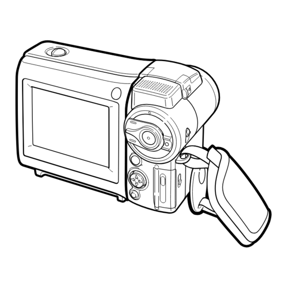
Page 7: Part Names
VL-MC500U/K 3. PART NAMES For details on the use of each control. Light adjustment sensor Remote sensor Flash cover release Flash Media Selection switch ( Tape mode/ Card mode selection switch) Start/Stop button Hand strap Card slot cover release PHOTO button... -
Page 8: Disassembly Of The Set
VL-MC500U/K 4. DISASSEMBLY OF THE SET Note: Before removing the cabinet, turn off the power supply, and ascertain that the battery have been removed. LCD Panel Battery Unit 1) Detach the battery unit. 1) Remove the FPC of the LCD panel, and detach the LCD panel 2) Remove the three screws ((d)XiPSN17P03000). - Page 9 VL-MC500U/K 1) Take out the mechanism in the direction of the arrow. 2) Remove the three floating screws ((a)LX-BZ0251TAFD) and the one floating screw ((b)LX-BZ0253TAFN). 3) Remove the five screws ((d)XiPSN17P03000) to detach the battery cover. Battery Cover 1) Detach the lithium battery lid.
-
Page 10: Mechanism Adjustment Jigs And Parts
VL-MC500U/K 5. MECHANISM ADJUSTMENT JIGS AND PARTS Configuration 1. Name 5-1. Mechanism check adjustment jigs 2. Part No. 3. Code <Note: The entries of list> * Model, Uses Remarks 1. Tension gauge 4N 1. PB-use cassette 1. Dial tension gauge 1. -
Page 11: Inspection And Maintenance Items And Intervals
VL-MC500U/K 6. INSPECTION AND MAINTENANCE ITEMS AND INTERVALS In order to keep the mechanical section always in good condition, perform the following inspection and maintenance at regular intervals. In addition, after repair, perform the following maintenance items regardless of how long the user has been using the unit. -
Page 12: Mechanical Adjustments And Checks
VL-MC500U/K 7. MECHANICAL ADJUSTMENTS AND CHECKS The items discussed here relate to general on-site servicing (field servicing). Adjustments and replacements that require sophisticated facilities, jigs and technology are omitted. In addition, in order to maintain the characteristics that the unit has when it is new, not only are inspection and maintenance necessary, but it is absolutely necessary that, for example, the tape not be damaged, and always use jigs for adjustments that require them. - Page 13 VL-MC500U/K 7-4. Back tension torque check and adjustment in record (playback) mode Tension roller position (S guide standard) AC adapter used, with cassette controller assembly (1) Checking 0 ± 0.3 Set the torque cassette (SD-1015), and make sure in the SP record mode that...
- Page 14 VL-MC500U/K <REW back tension standard> (If the tension fluctuates, read its center value.) 15 ± 12mN 7-8. Checking of winding Tu reel base ratchet torque DC3V, without cassette controller assembly (Independent Mechanism) (1) Remove the cassette controller assembly, then apply DC3V to the loading motor and put the system into standby mode.
-
Page 15: Tape Running Adjustment
VL-MC500U/K 8. TAPE RUNNING ADJUSTMENT 8-1. Adjustment locations <Replacement parts> Adjust the height of only · T roller, arm replaced parts with the · Tu guide, arm adjusting jig. · Slide chassis Adjustment procedure 8-2 Running rough Running final Running adjustm-... - Page 16 VL-MC500U/K 8-4. Running rough adjustment (With cassette controller) 1) Su, Tu guide roller height adjustment Entrance side Exit side <Method and description> ±1/4 shift ±1/4 shift Normal (1) Loosen the guide roller lock screw, then tighten loosely so that the roller turns easily.
-
Page 17: Disassembly And Reassembly
VL-MC500U/K 9. MECHANICAL SECTION ASSEMBLY AND PARTS REPLACEMENT (DISASSEMBLY AND REASSEMBLY) Mechanical section disassembly and reassembly are explained in this section. For removal of the cabinet, etc., refer to 4. DISASSEMBLY OF THE SET. <Precautions> 1. Always replace cut washers that have been removed, for example in parts replacement, with new ones. - Page 18 VL-MC500U/K (6) STOP mode (5) PLAYBACK (RECORD, FF, VSF) mode The system is in the STOP (Rec Lock in CAMERA mode) The mechanism position for playback, record, FF and fast position; the S and the T pole bases are snap-fitted to the drum feed playback.
- Page 19 VL-MC500U/K 9-3. How to operate with the circuit board without the cassette controller assembly. In this method, if the procedure is followed incorrectly there is danger of damaging the mechanism and the tape, so except in special cases, such as when measuring the VSR torque, do not perform this procedure. Normally operate this unit with the cassette controller assembly attached.
- Page 20 VL-MC500U/K 9-5. Reassembly 9-5-1. Reassembly in side of the main chassis. Note) Numbers before part names are given as a guide to the order of assembly. As for greasing/oiling/cleaning places refer to the attached drawings (Grease/Oil application side of the main chassis).
- Page 21 VL-MC500U/K 9-5-2. Reassembly in side of the Slide chassis. Note) Numbers before part names are given as a guide to the order of assembly. As for greasing/oiling/cleaning places refer to the attached drawings (Grease/Oil application side of the slide chassis)
- Page 22 VL-MC500U/K 9-5-3. Main chassis assembly and slide chassis assembly assembling method (1) Enter the coupling mode. (In this position, the cam groove of the T arm operation lever in the figure is parallel to the side of the main chassis, and the poll base is slightly moved.)
- Page 23 VL-MC500U/K GREASE/OIL APPLICATION From rear surface side Rear surface · groove side surface Front surface · rear surface · groove From rear side surface surface side Drum base assembly Main cam Loading lever Tu loading arm S loading arm Intermediate gear angle...
-
Page 24: Adjusting The Electrical Circuits
VL-MC500U/K 10. ADJUSTING THE ELECTRICAL CIRCUITS Before starting the electric circuit adjustment • The adjustment methods described herein are used, in most cases, when the expendable mechanical parts, including the video head, have been replaced, at which time the electrical circuits need to be readjusted. Before adjusting the electrical circuits, make sure that the mechanism works properly (i.e., the mechanism is properly adjusted). - Page 25 VL-MC500U/K VL-MC500U/K Service jig configuration...
- Page 26 VL-MC500U/K [TEST POINT] (Wiring board diagram: Main Side A) TL1242(INT MIC R) TL1216(INT MIC L) EE level check EE level check Frequency character check Frequency character check C1201 TL604 TL1236 TL1245 R600 TL1237 TL1216 C3701 SC1202 TL1252 RMC701 SC1201 TL1210...
- Page 27 VL-MC500U/K [Making adjustments] Adjusting the servo system controller and related parts 1. Setting the system codes Replacement of IC705 E PROM requires the following data to be set in this order. [Procedure] Set the unit to the VCR mode and set the data for each address.
- Page 28 VL-MC500U/K 3. SHUT OFF adjustment Mode VCR ADJ mode Procedure 1) Load a recordable tape, and set the camera mode. 2) Press the "CONTINUE" and then the "TEST SEL" on the remote control for adjustment to enter the TEST mode (T-01 blinks).
- Page 29 VL-MC500U/K ADJUSTING THE VIDEO I/O CIRCUIT SYSTEM (Wiring board diagram: Main Side A) L907 C953 L912 Q903 R995 R956 TL908 R987 C957 C970 C973 J5701 FL5701 L916 R989 R988 Q907 C971 TL1474 L917 TL1473 R1477 PCO D/A-Y C974 TL1470 R1471...
- Page 30 VL-MC500U/K ADJUSTING THE LCD CIRCUIT * To make this adjustment, set the backlight switch to the "NORMAL" position. (Wiring board diagram: Main Side B) (Wiring board diagram: Main Side A) C2805 C2808 R2806 C420 TL4437 C419 R418 C418 TL4429 TL418...
-
Page 31: White Balance Adjustment
VL-MC500U/K 4. White Balance adjustment Test point LCD panel display surface Address VCR ADJ 584, VCR ADJ 586 Mode VCR AV input Procedure 1) Input the white 40% signal to AV input. 2) Input the white 40% signal to the standard monitor, and adjust it to become equal to that of the screen. - Page 32 VL-MC500U/K DV INTERFACE (IEEE1394) ID SETTING This unit has a DV interface function conforming to IEEE1394. Therefore, each individual ID number must be used for each unit. Since this ID is written on the E PROM (IC302) on the head amp PWB, the ID must be newly written when replacing this IC or the head amp PWB.
- Page 33 VL-MC500U/K (5) Click on [Repair use]. Click (6) Input the necessary information for the application. For the indispensable input items, be sure to input them. Select the [Group/company] and [Kind name] from the list. Input the [Model name]. Input the [Serial number].
-
Page 34: Camera Section Adjustments
VL-MC500U/K 10-2. Camera Section Adjustments 10-2-1. Camera section service (1) Camera adjustment is performed after the set has been completed. (2) Subjects, measuring instruments and jigs needed for camera section service and adjustments • Gray scale chart • Frequency counter •... - Page 35 VL-MC500U/K 4) Operation flow FF or REW PLAY FF or REW PLAY STOP Address is selected and specified, with the data called. Then the called data are selected and fixed. The operation flows in this sequence. 5) When the adjustment is complete: Press the "CONTINUE"...
- Page 36 VL-MC500U/K (4) Camera signal system adjustment mode In the camera signal system adjustment mode, the automatic white balance is disabled to allow for the adjustment of the camera unit. At this time, the white balance mode is fixed at the INDOORS mode and the focus mode is switched to the manual focus mode.
- Page 37 VL-MC500U/K 10-2-4. Adjustment procedures Item Adjustment method (1) Auto-focus adjustment Set the unit to the auto-focus function adjustment mode and write data to the address "13FD" one after another. This executed the adjustments automatically. The items to be adjusted are as listed below. Every time an adjustment is made properly, the data "FF"...
- Page 38 VL-MC500U/K Adjustment method Item (4) Iris AE coarse adjustment (1) Video output is observed with the oscilloscope in the grey scale standard record state, • Measurement terminal: the data of address "0002" is rewritten, and the luminance signal level is adjusted white to 680 ±...
- Page 39 VL-MC500U/K Adjustment method Item (1) White balance adjustment is performed repeatedly. (7) White balance adjustment • Measurement terminal: EE output • Address: "0128" INDOOR_W/B R "012A" INDOOR_W/B R • Measuring instrument: Vector scope • Object: Grey scale • Data variation width: "0000"...
- Page 40 VL-MC500U/K Item Adjustment method (12) Iris AE adjustment (1) Set the unit to the normal operation mode (write the data " FF" to the address • Measurement terminal: "0000"). S terminal luminance signal output (2) Observe the video output with an oscilloscope in the gray scale standard recording (75 Ω...
-
Page 41: Useful Tips
VL-MC500U/K 11. USEFUL TIPS (PROBLEMS DIFFER FROM THOSE FOUND ON VHS OR 8MM DECKS BECAUSE THE SIGNALS ARE DIGITALLY PROCESSED.) Camera (EE mode) Camera (REC mode) VCR (EE mode) VCR (PB mode) Picture fails to appear when tape Picture fails... -
Page 42: Signal Flow Diagrams
VL-MC500U/K 12. SIGNAL FLOW DIAGRAMS 12-1. EE MODE FLOW (VIDEO) WAVEFORM DIAGRAM (DURING COLOR BAR RECORDING) IC4401 291pin Y/YC Output CAM ADIN CH1=500mV 20µs/d DC P*10 IC201 CAM ENGINE IC4401 23pin ZYP3 Input 5ms/d CH1=1V DC P*10 28 31 35 37 38... - Page 43 VL-MC500U/K WAVEFORM DIAGRAM 12-3. FLOW IN PB MODE (VIDEO) (DURING COLOR BAR PLAYBACK) HEAD AMP IC3401 39pin PBDATA Input IC3401 32pin Output 5ms/d PB_DATA 5ms/d CH1=500mV CH1=500mV DC P*10 DC P*10 B TO B SC3301 PB_DATA IC3401 EQ/PLL IC3401 44pin Input...
- Page 44 VL-MC500U/K 12-5. FLOW IN PB MODE (AUDIO) WAVEFORM DIAGRAM (1.6 kHz SINE WAVE) From IC3404 same as in Video PB system 10µs/d CH1=1V DC P*10 IC452 REC/PB ENGINE DODAT 16Bit ADC/DAC IC1602 AUD-R_DA_OUT AUD-L_DA_OUT IC600 AUDIO-R_IN/OUT SP(+) AUDIO-L_IN/OUT SP(-)
-
Page 45: Block Diagrams
VL-MC500U/K 13. BLOCK DIAGRAMS 13-1. SYSTEM BLOCK DIAGRAM... - Page 46 VL-MC500U/K 13-2. CAMERA SECTION BLOCK DIAGRAM...
- Page 47 VL-MC500U/K 13-3. VIO ENGINE SECTION BLOCK DIAGRAM...
- Page 48 VL-MC500U/K 13-4. REC/PB SECTION BLOCK DIAGRAM...
- Page 49 VL-MC500U/K 13-5. AUDIO/DIGITAL OUTPUT SECTION BLOCK DIAGRAM...
- Page 50 VL-MC500U/K 13-6. CAMERA CIRCUIT BLOCK DIAGRAM...
- Page 51 VL-MC500U/K - M E M O -...
-
Page 52: Schematic Diagrams
VL-MC500U/K 14. SCHEMATIC DIAGRAMS 14-1. OVERALL SCHEMATIC DIAGRAM 52~53... - Page 53 VL-MC500U/K 14-2. CAMERA ENGINE SCHEMATIC DIAGRAM 54~55...
- Page 54 VL-MC500U/K 14-3. REC/PB ENGINE SCHEMATIC DIAGRAM 56~57...
- Page 55 VL-MC500U/K 14-4. AUDIO I/O SCHEMATIC DIAGRAM 58~59...
- Page 56 VL-MC500U/K 14-5. MEC/SYS MiCON SCHEMATIC DIAGRAM 60~61...
- Page 57 VL-MC500U/K 14-6. POWER2 SCHEMATIC DIAGRAM (VL-MC500K) å AND SHADED COMPONENTS=SAFETY RELATED PARTS å å å å 62~63...
- Page 58 VL-MC500U/K 14-7. POWER2 SCHEMATIC DIAGRAM (VL-MC500U) å AND SHADED COMPONENTS=SAFETY RELATED PARTS å å å å å 64~65...
- Page 59 VL-MC500U/K 14-8. CAMERA CONN SCHEMATIC DIAGRAM 66~67...
- Page 60 VL-MC500U/K 14-9. VIDEO I/O SCHEMATIC DIAGRAM 68~69...
- Page 61 VL-MC500U/K 14-10. MOTOR DRIVER SCHEMATIC DIAGRAM 70~71...
- Page 62 VL-MC500U/K 14-11. POWER1 SCHEMATIC DIAGRAM 72~73...
- Page 63 VL-MC500U/K 14-12. LCD SCHEMATIC DIAGRAM 74~75...
- Page 64 VL-MC500U/K 14-13. CONNECTION(B-B) SCHEMATIC DIAGRAM 76~77...
- Page 65 VL-MC500U/K 14-14. EQ/PLL SCHEMATIC DIAGRAM 78~79...
- Page 66 VL-MC500U/K 14-15. CAM/CARD MiCON SCHEMATIC DIAGRAM 80~81...
- Page 67 VL-MC500U/K 14-16. VIDEO I/O ENGINE SCHEMATIC DIAGRAM 82~83...
- Page 68 VL-MC500U/K 14-17. DAC SCHEMATIC DIAGRAM 84~85...
- Page 69 VL-MC500U/K 14-18. USB/SD CTL SCHEMATIC DIAGRAM 86~87...
- Page 70 VL-MC500U/K 14-19. LENS MiCON SCHEMATIC DIAGRAM 88~89...
- Page 71 VL-MC500U/K 14-20. LENS CONN SCHEMATIC DIAGRAM 90~91...
- Page 72 VL-MC500U/K 14-21. LENS DRIVE SCHEMATIC DIAGRAM 92~93...
- Page 73 VL-MC500U/K 14-22. CARD CONN SCHEMATIC DIAGRAM 94~95...
- Page 74 VL-MC500U/K 14-23. MICAMP SCHEMATIC DIAGRAM 96~97...
- Page 75 VL-MC500U/K 14-24. INVERTER SCHEMATIC DIAGRAM å AND SHADED COMPONENTS=SAFETY RELATED PARTS å 98~99...
- Page 76 VL-MC500U/K 14-25. CCD SCHEMATIC DIAGRAM 100~101...
- Page 77 VL-MC500U/K 14-26. TG SCHEMATIC DIAGRAM 102~103...
- Page 78 VL-MC500U/K 14-27. CDS SCHEMATIC DIAGRAM 104~105...
- Page 79 VL-MC500U/K 14-28. HEAD AMP SCHEMATIC DIAGRAM 106~107...
-
Page 80: Semiconductor Lead Identification
VL-MC500U/K 15. SEMICONDUCTOR LEAD IDENTIFICATION 3LN01S HN2A01FU 2SC4738Y 2SA1588Y KRX203U 3LP01S HN2C01FU FMMT717 KRC404E KTX101UY XP05534 FMMT619 KTA2014EY RN4986 HN1B04FU 2SC4213B KTC4075EY RT1N144U 2SC5376B 2SC4627CD RT1P441U CPH3206 RT1N141U 2SC5383F CPH5504 FMG12 MC2852 2SC4944Y TCSZ04U TA75S01F RN1704 S80937AN S817B28C MA132WK NDS332P... - Page 81 VL-MC500U/K HVC202A KV1812K HVU362 EX1394CE HVU359TR LB11990W BH7277KV LA74206W MB3881++ MN52A6CD NJM2902V PCM3008 H49334HN MB8346BV IXA353WJ MM1449XQ LA73070V MM1323XV UPD16S10 ADC08351 RS5C313/ IX0785TA NJM2143R IXA204WJ TLC2940 NJU7015R IX0809TA TE4100HW NJM2535V IXA352WJ SN2G53CT IXA307WJ BR24C64F IXA306WJ HJM2140R IXA193WJ IXA320WJ...
- Page 82 VL-MC500U/K 16. PRINTED WIRING BOARD ASSEMBLIES MAIN PWB SIDE A TL1236 C1201 TL604 TL1245 R600 TL1237 TL1216 C3701 TL1252 SC1202 SC1201 RMC701 TL1210 L3701 TL1225 TL1214 TL1227 TL605 R643 L600 TL1258 TL606 TL1242 TL1240 TL1235 TL1207 TL1269 TL1222 TL1271 TL1263...
- Page 83 VL-MC500U/K SIDE B R701 TL607 C722 C728 Q705 R658 C704 C631 D703 C624 R630 TL790 R750 R605 C622 R655 IC706 R749 C620 C724 C238 TL601 C626 IC707 R762 R766 C725 C726 C738 VA602 FB600 IC203 R761 R765 R753 R752 R623...
- Page 84 VL-MC500U/K CAMERA PWB SIDE A R2501 R2503 R2530 R2528 C2521 IC2501 R2531 C2502 C2506 C2516 R2504 R556 C2507 L501 R510 C2512 C2513 R2509 R502 R2510 C2503 C507 C510 TL1027 R509 IC501 TL513 TL1033 C505 C1016 TL511 TL512 R1019 TL510 TL514...
- Page 85 VL-MC500U/K SIDE B TL2514 R2529 R2524 TL2505 Q2503 R2522 TL2503 TL2516 TL2501 TL2512 R2518 Q2502 R2517 TL2509 R2532 C1018 TL2502 TL2511 TL2513 C1019 TL1039 C1001 C2514 TL2515 C1017 TL1037 R2533 TL2517 TL1036 TL1001 R1013 TL2518 TL2510 TL2504 TL1002 TL2506 TL1003...
- Page 86 VL-MC500U/K CARD PWB SIDE A SC1501 P1504...
- Page 87 VL-MC500U/K SIDE B R6606 C6607 C6603 TL6603 C6610 C6606 R6602 R6610 R6605 TL1503 TL1520 R6604 TL1515 TL1518 C1500 IC6601 TL1505 TL1527 R1514 TL6601 R1500 TL6602 TL1524 C6601 R1501 R1505 TL1523 R6601 R6609 R6607 TL1504 R1502 R1506 TL1501 C6602 C6611 C6608...
- Page 88 VL-MC500U/K INVERTER PWB SIDE A Q9801 TL9804 C9810 L9801 TL9802 TL9807 C9812 TL9801 TL9806 TL9817 TL9805 TL9813 TL9815 TL9816 TL9814 TL9818 TL9803 SC9802...
- Page 89 VL-MC500U/K SIDE B SW9800...
- Page 90 VL-MC500U/K CCD PWB SIDE A TL91 RMC91 TL93 TL92 TL2 TL3 TL12 C2 TL10 TL14 TL13 C109 TL11 TL109 IC21 TL107 TL111 TL112 FB22 SC101 TL102 TL8 TL103 TL104TL105TL106TL108TL110TL113...
- Page 91 VL-MC500U/K SIDE B P101 TL126 C110 TL125 C115 C108 C114 R106 TL124 R107 C102 R102 TL123 C107 IC101 R108 TL122 C101 R109 TL121 R103 TL120 R110 C104 TL119 C105 C111 L101 TL118 TL117 L102 TL116 TL115...
- Page 92 VL-MC500U/K HEAD AMP PWB Component Side SIDE A R332 C320 C315 R330 R331 R333 R321 R308 C322 C304 R320 Q302 C331 C307 C330 R318 P306 C305 R312 C324 R323 C319 C311 R304 R325 C333 Q303 C301 C327 R324 C332 C342...
- Page 93 VL-MC500U/K Component Side SIDE B C345 L301 C303 Wiring Side SIDE B C345 L301 C303...
- Page 94 VL-MC500U/K - M E M O -...
-
Page 95: Printed Wiring Board Assemblies
IXA193WJ, ECC " HOW TO ORDER REPLACEMENT PARTS " External Memory IC452 RH-iX0809TAZZQ IX0809TA, Codec/ECC/ PCM/CLK.GEN/DIF in USA: Contact your nearest SHARP Parts Distributor. For loca- IC600 VHiLA74206W-1Q LA74206W tion of SHARP Parts Distributor, IC701 RH-iXA352WJPZQ IXA352WJ, Mec/System Call Toll-free 1-IBE800-SHARP... - Page 96 VL-MC500U/K VL-SD20U Ref. No. Part No. Description Code Ref. No. Part No. Description Code L471 VPD9M100J1R7NY Peaking, 10µH Q1403 VS2SC5376B+-1Y 2SC5376B+ L600 VPCEM470M3R7NY Peaking, 47µH Q1404 VSKRX203U++-1Y KRX203U++ L601 VPBWM100KR50NY Peaking, 10µH Q1405 VS2SC5376B+-1Y 2SC5376B+ Q1431 VSRN4986///-1Y RN4986 L701 VPCEM100MR70NY Peaking, 10µH...
- Page 97 VL-MC500U/K Ref. No. Part No. Description Code Ref. No. Part No. Description Code C403 RC-KZ0083TAZZY 10V Ceramic C702 VCKYCY0JF105ZY 6.3V Ceramic C703 VCKYCZ1CB103KS 0.01 16V Ceramic C404 VCSATA1AJ475MY 10V Tantalum C704 VCKYTV1AB105KY 10V Ceramic C405 VCKYCZ1AB473KY 0.047 10V Ceramic C705 VCKYCZ1CB103KS 0.01...
- Page 98 VL-MC500U/K VL-SD20U Ref. No. Part No. Description Code Ref. No. Part No. Description Code C956 RC-KZ0044TAZZY 10V Ceramic C1717 VCKYCZ1AF104ZY 10V Ceramic C957 VCKYTV1AB105KY 10V Ceramic C1718 VCKYCZ1AF104ZY 10V Ceramic C959 VCKYTV1EB104KY 25V Ceramic C1719 VCKYCY0JF105ZY 6.3V Ceramic C960 RC-KZ0070TAZZY...
- Page 99 VL-MC500U/K Ref. No. Part No. Description Code Ref. No. Part No. Description Code C3452 VCKYCZ1CB103KS 0.01 16V Ceramic C7402 VCKYCZ1CB103KS 0.01 16V Ceramic C3454 VCKYCY0JB105KY 6.3V Ceramic C7403 VCKYCZ1CB103KS 0.01 16V Ceramic C3455 VCKYCZ1CB103KS 0.01 16V Ceramic C7404 VCKYCZ1EB472KY 4700p 25V Ceramic...
- Page 100 VL-MC500U/K VL-SD20U Ref. No. Part No. Description Code Ref. No. Part No. Description Code R478 VRS-CZ1JF823JY 82k 1/16W Metal Oxide R717 VRS-CZ1JF102JY 1/16W Metal Oxide R600 VRS-CY1JF000JY 1/16W Metal Oxide R718 VRS-CZ1JF102JY 1/16W Metal Oxide R601 VRS-CY1JF000JY 1/16W Metal Oxide...
- Page 101 VL-MC500U/K Ref. No. Part No. Description Code Ref. No. Part No. Description Code R928 VRS-CZ1JF103JY 10k 1/16W Metal Oxide R1472 VRS-CZ1JF000JY 1/16W Metal Oxide R929 VRS-CZ1JF823DY 82k 1/16W Metal Oxide R1475 VRS-CY1JF000JY 1/16W Metal Oxide R930 VRS-CZ1JF333JY 33k 1/16W Metal Oxide...
- Page 102 VL-MC500U/K VL-SD20U Ref. No. Part No. Description Code Ref. No. Part No. Description Code R3489 VRS-CZ1JF332JY 3.3k 1/16W Metal Oxide R2820 VRS-CZ1JF223JY 22k 1/16W Metal Oxide R3492 VRS-CZ1JF821JY 820 1/16W Metal Oxide R2821 VRS-CZ1JF154JY 150k 1/16W Metal Oxide R2822 VRS-CZ1JF473JY...
- Page 103 VL-MC500U/K Ref. No. Part No. Description Code Ref. No. Part No. Description Code DUNTKB323QA00 R7415 VRS-CZ1JF560DY 1/16W Metal Oxide CAMERA PWB UNIT R7416 VRS-CZ1JF560DY 1/16W Metal Oxide R7417 VRS-CZ1JF560DY 1/16W Metal Oxide R7418 VRS-CZ1JF560DY 1/16W Metal Oxide INTEGRATED CIRCUITS R7419...
- Page 104 VL-MC500U/K VL-SD20U Ref. No. Part No. Description Code Ref. No. Part No. Description Code R508 VRS-CZ1JF102JY 1/16W Metal Oxide Q1501 VSKTA2014EY-1Y KTA2014EY R509 VRS-CZ1JF273JY 27k 1/16W Metal Oxide Q6600 VSKTC4075EY-1Y KTC4075EY R510 VRS-CZ1JF102JY 1/16W Metal Oxide R512 VRS-CZ1JF000JY 1/16W Metal Oxide...
- Page 105 VL-MC500U/K Ref. No. Part No. Description Code Ref. No. Part No. Description Code MISCELLANEOUS PARTS C114 VCKYCZ1AF104ZY 10V Ceramic C115 VCSATA0JJ156MY 6.3V Tantalum SC9801 QSOCN0871TAZZY Socket, 8Pin C116 VCCCCZ1HH221JY 220p 50V Ceramic SC9802 QCNCWA002WJZZY Connector, 4Pin SW9800 QSW-M0019TAZZY Switch RESISTORS...
- Page 106 VL-MC500U/K VL-SD20U Ref. No. Part No. Description Code Ref. No. Part No. Description Code COIL MECHANISM PARTS L301 VPAWM4R7MR70N Coil, 4.7µH LCHSM0181GEZZ Main Chassis Ass’y CAPACITORS MLEVF0539GEFW Eject Control Lever C301 VCKYCZ1HB102K 1000p 50V Ceramic MLEVF0502GEFW Pinch Control Lever C302 VCKYCZ1HF103Z 0.01...
- Page 107 VL-MC500U/K Ref. No. Part No. Description Code Ref. No. Part No. Description Code MSPRP0185GEZZ PB Guide SPR. CABINET PARTS LIST LX-WZ1071GE02 CW ø 0.7 ø 1.8t0.1 LX-WZ1104GE06 CW ø 0.7 ø 2.2t0.25 LX-WZ1029GE00 CW ø 1.2 ø 3t0.25 TLABMA117WJZZ Model Label(MC500U) LZ-WZ1105GE00 W ø...
- Page 108 VL-MC500U/K VL-SD20U Ref. No. Part No. Description Code Ref. No. Part No. Description Code 12-4 MSPRDA011WJFJ Strobe Up Spring CAMERA UNIT PARTS LIST 12-5 PCOVPA005WJZZ Strobe Soundproof Sheet 12-6 KLMPWA004WJZZ Strobe Unit PLNSAA001WJN1 Lens CANGKA021WJ01 KS LCD Earth Plate LANGKA027WJFW...
- Page 109 VL-MC500U/K Ref. No. Part No. Description Code Ref. No. Part No. Description Code SUPPLIED ACCESSORIES ACCESSORIES å QACCZ0053TAPZ AC Cable(MC500K) QCNW-A338WJZZ USB Cable QCNW-A400WJZZ AV/S Cable RRMCG0104TASA Remote Control å UADP-0339TAZZ AC Adapter(MC500U) å UADP-0341TAZZ AC Adapter(MC500K) UBATi0086TAZZ Battery Pack...
- Page 110 VL-MC500U/K VL-SD20U MECHANISM CHASSIS EXPLODED VIEW Ref. No. Part No. Description Code Ref. No. Part No. Description Code 411~ 411~ +0.5 +0.5...
- Page 111 VL-MC500U/K LENS UNIT EXPLODED VIEW Ref. No. Part No. Description Code Ref. No. Part No. Description Code 12-6 11-6 12-4 12-3 12-2 11-2 12-5 11-4 9-19 9-13 9-10 9-12 11-3 9-11 11-5 9-14 10-8 9-18 10-14 9-15 10-5 10-6 10-9...
- Page 112 VL-MC500U/K VL-SD20U CABINET EXPLODED VIEW Ref. No. Part No. Description Code Ref. No. Part No. Description Code 6-19 6-18 15-2 6-17 14-2 1-11 6-16 6-16 6-16...
- Page 113 VL-MC500U/K CASSETTE CONTROL EXPLOOD VIEW Ref. No. Part No. Description Code Ref. No. Part No. Description Code 4±0.5 8.5±0.5 CAMERA UNIT EXPLOOD VIEW...
- Page 114 VL-MC500U/K VL-SD20U VL-MC500U/K SERVICE JIG SPECIFICATIONS Ref. No. Part No. Description Code Ref. No. Part No. Description Code 1-1. Adjusting jigs for checking the mechanism Name New part Type number, Application Part code Code PB-use cassette torque meter 1mN·m/1.5mN·m 9DASD-1015...
-
Page 115: Packing Of The Set
VL-MC500U/K 18. PACKING OF THE SET Ref. No. Part No. Description Code Ref. No. Part No. Description Code SPAKP6129TAZZ RRMCG0104TASA Wrapping Paper Remote Control åQACCZ0053TAPZ(MC500K) RCORFA012WJZZ AC Cable Ferrite Core(x2) UBATL0011TAZZ Lithium Battery CDSKA0080TA01 SD Card(8MB) UBATL0015TAZZ QCNW-A338WJZZ Lithium Battery... - Page 116 Code Ref. No. Part No. Description Code COPYRIGHT C 2002 BY SHARP CORPORATION ALL RIGHTS RESERVED. No part of this publication may be reproduced, stored in a retrieval system, or transmitted in any form or by any means, electronic, mechanical, photocopying, recording, or otherwise, without prior written permission of the publisher.
Need help?
Do you have a question about the VL-MC500U and is the answer not in the manual?
Questions and answers