Table of Contents
Advertisement
Quick Links
1. SPECIFICATIONS .............................................................................................................................. 2
2. PART NAMES .................................................................................................................................... 3
3. DISASSEMBLY OF THE SET ............................................................................................................ 4
4. MECHANISM ADJUSTMENT JIGS AND PARTS .............................................................................. 6
ITEMS AND INTERVALS ................................................................................................................... 7
6. MECHANICAL ADJUSTMENTS AND CHECKS ................................................................................ 8
7. TAPE RUNNING ADJUSTMENT ..................................................................................................... 11
(DISASSEMBLY AND REASSENBLY) ........................................................................................... 13
9. ADJUSTING THE ELECTRICAL CIRCUITS .................................................................................... 20
10.USEFUL TIPS ................................................................................................................................... 41
11.SIGNAL FLOW DIAGRAMS ............................................................................................................. 42
12.BLOCK DIAGRAMS ......................................................................................................................... 45
13.SCHEMATIC DIAGRAMS ................................................................................................................ 52
14.SEMICONDUCTOR LEAD IDENTIFICATION ............................................................................... 106
15.PRINTED WIRING BOARD ASSEMBLIES .................................................................................... 108
16.REPLACEMENT PARTS LIST ....................................................................................................... 121
17.PACKING OF THE SET ................................................................................................................. 144
SERVICE MANUAL
LIQUID CRYSTAL DIGITAL CAMCORDER
MODELS
In the interests of user-safety (Required by safety regula-
tions in some countries) the set should be restored to its
original condition and only parts identical to those specified
be used.
CONTENTS
SHARP CORPORATION
1
VL-ME100S/H/E
S21P3VL-ME100
VL-ME100S
VL-ME100H
VL-ME100E
Page
PAL
Advertisement
Table of Contents

Related Manuals for Sharp VL-ME100S


Summary of Contents for Sharp VL-ME100S
-
Page 1: Table Of Contents
VL-ME100S/H/E SERVICE MANUAL S21P3VL-ME100 LIQUID CRYSTAL DIGITAL CAMCORDER VL-ME100S VL-ME100H VL-ME100E MODELS In the interests of user-safety (Required by safety regula- tions in some countries) the set should be restored to its original condition and only parts identical to those specified be used. -
Page 2: Specifications
VL-ME100S/H/E 1. SPECIFICATIONS Signal System: PAL standard Recording System: 2 rotary heads, helical scanning system Cassette: Digital VCR Mini DV video cassette Recording/Playback Time: 90 minutes (DVM60, LP mode) Tape Speed: SP mode: 18.831 mm/second LP mode: 12.568 mm/second Pickup Device: 1/3.6" (effective size: 5.0 mm) CCD image sensor (with approx. -
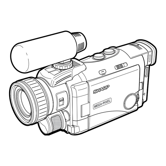
Page 3: Part Names
VL-ME100S/H/E 2. PART NAMES For details on the use of each control. Power Zoom W (Wide angle) / Left view Front view T (Telephoto) control buttons/ Manual Selection switch VOLume control buttons Accessory shoe DISPLAY ON/OFF button Viewfinder Manual Focus ring... -
Page 4: Disassembly Of The Set
VL-ME100S/H/E 3. DISASSEMBLY OF THE SET Note: Before removing the cabinet, turn off the power supply, and ascertain that the battery have been removed. Note: After the cabinet B is inserted between the zoom unit and the ANG, it is secured with screw. - Page 5 VL-ME100S/H/E • Remove the screws ((b)XiPSF17P03000)(2 pcs.) fix- ing the cabinet A to remove the V lid lock angle. • Remove each FPC of the main PWB. Lens fixing holder • Remove the screws ((e)XiPSN17P03000)(3 pcs.) fixing the main PWB to remove it.
-
Page 6: Mechanism Adjustment Jigs And Parts
VL-ME100S/H/E 4. MECHANISM ADJUSTMENT JIGS AND PARTS Configuration 1. Name 4-1. Mechanism check adjustment jigs 2. Part No. 3. Code <Note: The entries of list> * Model, Uses Remarks 1. Tension gauge 4N 1. PB-use cassette 1. Torque gauge 1. Torque gauge head 1. -
Page 7: Inspection And Maintenance Items And Intervals
VL-ME100S/H/E 5. INSPECTION AND MAINTENANCE ITEMS AND INTERVALS In order to keep the mechanical section always in good condition, perform the following inspection and maintenance at regular intervals. In addition, after repair, perform the following maintenance items regardless of how long the user has been using the unit. -
Page 8: Mechanical Adjustments And Checks
VL-ME100S/H/E 6. MECHANICAL ADJUSTMENTS AND CHECKS The items discussed here relate to general on-site servicing (field servicing). Adjustments and replacements that require sophisticated facilities, jigs and technology are omitted. In addition, in order to maintain the characteristics that the unit has when it is new, not only are inspection and maintenance necessary, but it is absolutely necessary that, for example, the tape not be damaged, and always use jigs for adjustments that require them. -
Page 9: Back Tension Torque Check And Adjustment In Record (Playback) Mode
VL-ME100S/H/E 6-4. Back tension torque check and adjustment in record (playback) mode Tension roller position (S guide standard) AC adapter used, with cassette controller assembly 0 ± 0.3 (1) Checking Set the torque cassette (SD-1015), and make sure in the SP record mode that... -
Page 10: Checking Of Winding Tu Reel Base Ratchet Torque
VL-ME100S/H/E <REW back tension standard> (If the tension fluctuates, read its center value.) 15 ± 12mN 6-8. Checking of winding Tu reel base ratchet torque DC3V, without cassette controller assembly (Independent Mechanism) (1) Remove the cassette controller assembly, then apply DC3V to the loading motor and put the system into standby mode. -
Page 11: Tape Running Adjustment
VL-ME100S/H/E 7. TAPE RUNNING ADJUSTMENT 7-1. Adjustment locations <Replacement parts> Adjust the height of only · T roller, arm replaced parts with the · Tu guide, arm adjusting jig. · Slide chassis Adjustment procedure 7-2 Running rough Running final Running adjustm-... -
Page 12: Running Rough Adjustment
VL-ME100S/H/E 7-4. Running rough adjustment (With cassette controller) 1) Su, Tu guide roller height adjustment Entrance side Exit side <Method and description> ±1/4 shift ±1/4 shift Normal (1) Loosen the guide roller lock screw, then tighten loosely so that the roller turns easily. -
Page 13: Mechanical Section Assembly And Parts Replacement (Disassembly And Reassenbly)
VL-ME100S/H/E 8. MECHANICAL SECTION ASSEMBLY AND PARTS REPLACEMENT (DISASSEMBLY AND REASSEMBLY) Mechanical section disassembly and reassembly are explained in this section. For removal of the cabinet, etc., refer to 3. DISASSEMBLY OF THE SET. <Precautions> 1. Always replace cut washers that have been removed, for example in parts replacement, with new ones. -
Page 14: Cassette Controller Assembly
VL-ME100S/H/E (6) STOP mode (5) PLAYBACK (RECORD, FF, VSF) mode The system is in the STOP (Rec Lock in CAMERA mode) The mechanism position for playback, record, FF and fast position; the S and the T pole bases are snap-fitted to the drum feed playback. -
Page 15: How To Operate With The Circuit Board Without The Cassette Controller Assembly
VL-ME100S/H/E 8-3. How to operate with the circuit board without the cassette controller assembly. In this method, if the procedure is followed incorrectly there is danger of damaging the mechanism and the tape, so except in special cases, such as when measuring the VSR torque, do not perform this procedure. Normally operate this unit with the cassette controller assembly attached. - Page 16 VL-ME100S/H/E 8-5. Reassembly 8-5-1. Reassembly in side of the main chassis. Note) Numbers before part names are given as a guide to the order of assembly. As for greasing/oiling/cleaning places refer to the attached drawings (Grease/Oil application side of the main chassis).
-
Page 17: Reassembly In Side Of The Slide Chassis
VL-ME100S/H/E 8-5-2. Reassembly in side of the Slide chassis. Note) Numbers before part names are given as a guide to the order of assembly. As for greasing/oiling/cleaning places refer to the attached drawings (Grease/Oil application side of the slide chassis) -
Page 18: Main Chassis Assembly And Slide Chassis Assembly Assembling Method
VL-ME100S/H/E 8-5-3. Main chassis assembly and slide chassis assembly assembling method (1) Enter the coupling mode. (In this position, the cam groove of the T arm operation lever in the figure is parallel to the side of the main chassis, and the ball base is slightly moved.) -
Page 19: Grease/Oil Application
VL-ME100S/H/E GREASE/OIL APPLICATION From rear surface side Rear surface · groove side surface Front surface · rear surface · groove From rear side surface surface side Drum base assembly Main cam Loading lever Tu loading arm S loading arm Intermediate gear angle... -
Page 20: Adjusting The Electrical Circuits
VL-ME100S/H/E 9. ADJUSTING THE ELECTRICAL CIRCUITS Before starting the electric circuit adjustment • The adjustment methods described herein are used, in most cases, when the expendable mechanical parts, including the video head, have been replaced, at which time the electrical circuits need to be readjusted. Before adjusting the electrical circuits, make sure that the mechanism works properly (i.e., the mechanism is properly adjusted). - Page 21 VL-ME100S/H/E VL-ME100S/H/E Service jig configuration QSW-Z0353TAZZ Card PWB Mechanism Product unit Product unit Product unit Product unit QCNW-1832 CPWBH2989TA01 QSW-Z0358TAZZ TAZZ QCNW-1832 TAZZ 10pin QCNW-1371TAZZ Product unit Card CPWBH2876 TA01 Zoom QSW-Z0354TAZZ Hot Shoe Product unit To LCD Product unit...
- Page 22 VL-ME100S/H/E [TEST POINT] C1704 R3495 C1708 R3443 C8829 R3474 R3448 L1906 IC707 R3475 X701 R3440 SC5701 R3447 Q3403 L8804 R1721 R3493 R3444 L8805 L3405 R3492 C1724 R6661 R6665 R6629 C6622 C3473 C6659 C6630 R6666 R1955 R6642 R6624 R1713 Q6607 C3431...
- Page 23 VL-ME100S/H/E...
-
Page 24: Manual Adjustment
VL-ME100S/H/E [Making adjustments] Adjusting the servo system controller and related parts 1. Setting the system codes Replacement of IC705 E PROM requires the following data to be set in this order. [Procedure] Set the unit to the VCR mode and set the data for each address. -
Page 25: Adjusting The Electromagnetic Conversion Circuit System
VL-ME100S/H/E 3. SHUT OFF adjustment Mode VCR ADJ mode Procedure 1) Load a recordable tape, and set the camera mode. 2) Press the "CONTINUE" and then the "TEST SEL" on the remote control for adjustment to enter the TEST mode (T-01 blinks). -
Page 26: Adjusting The Video I/O Circuit System
VL-ME100S/H/E ADJUSTING THE VIDEO I/O CIRCUIT SYSTEM (Wiring board diagram: Main Side A) SC201 R4437 R4436 R4443 TL4403 R4442 TL4404 R4441 C4441 R4477 C4410 R4485 R4475 R4499 Q4482 R4488 Q4472 R4487 C4482 R247 Q4431 Q4481 R4486 TL4441 C4485 C4483 TL1480... -
Page 27: Adjusting The Lcd Circuit
VL-ME100S/H/E ADJUSTING THE LCD CIRCUIT * To make this adjustment, set the backlight switch to the "NORMAL" position. (Wiring board diagram: LCD Side A) TL1820(G-OUT) TL1810(G-OUT) TL1825 Black level Black level Contrast Contrast TL835 R1836 R1834 C1813 C1809 TL1825 C1823... -
Page 28: Com-Bias Adjustment
VL-ME100S/H/E 4. COM-Bias adjustment Test point LCD panel display area Address Mode VCR AV input Procedure 1) Input white 40% signal into the AV input. 2) Set the illuminometer (TOPCON IM-3) on the LCD panel surface. (Shut off the external light.) 3) Minimize the ripple of output waveform of illuminometer. -
Page 29: Vf Vco Adjustment
VL-ME100S/H/E VIDEO I/O ENG DAC CIRCUIT C1711 R1702 TL7823(GND) C1701 (Wiring board diagram: Main Side A) L1701 R1703 C1702 DAC LCD_Y, DAC LCD_R-Y, R1704 R1707 R1709 DAC LCD_B-Y R1708 R4418 C1710 TL202 C4424 R4426 R4419 C1712 C1706 TL204 C4420 TL4415... - Page 30 VL-ME100S/H/E 10. VF brightness adjustment Test point TL8841(VG) Address VCR ADJ 80 Mode VCR AV input Procedure 1) Use 3-STEP staircase wave as an input signal. 2) Change VCR ADJ 8C to 1F. 3) Adjust the waveform of TL8841 between pedestals to the specified level.
-
Page 31: Adjusting The Mic Amp Circuit
VL-ME100S/H/E 14. VF sub-brightness R/B adjustment Test point TL8842(VR), TL8841(VG), TL8843(VB) Address VCR ADJ 81(R), VCR ADJ 82(B) Mode VCR AV input Procedure 1) Input white 40% signal into the AV input and standard monitor. 2) Adjust it with the VCR ADJ 81/82 so as to obtain the same color as the standard monitor. - Page 32 VL-ME100S/H/E DV INTERFACE (IEEE1394) ID SETTING This unit has a DV interface function conforming to IEEE1394. Therefore, each individual ID number must be used for each unit. Since this ID is written on the E PROM (IC302) on the head amp PWB, the ID must be newly written when replacing this IC or the head amp PWB.
- Page 33 VL-ME100S/H/E (5) Click on [Repair use]. Click (6) Input the necessary information for the application. For the indispensable input items, be sure to input them. Select the [Group/company] and [Kind name] from the list. Input the [Model name]. Input the [Serial number].
- Page 34 VL-ME100S/H/E 9-2. Camera Section Adjustments 9-2-1. Camera section service (1) Camera adjustment is performed after the set has been completed. (2) Subjects, measuring instruments and jigs needed for camera section service and adjustments • Gray scale chart • Frequency counter •...
- Page 35 VL-ME100S/H/E 4) Operation flow FF or REW PLAY FF or REW PLAY STOP Address is selected and specified, with the data called. Then the called data are selected and fixed. The operation flows in this sequence. 5) When the adjustment is complete: Press the "CONTINUE"...
- Page 36 VL-ME100S/H/E 2) Shifting to the normal operation mode Set the data for the address "0000" to " FF". This shifts the mode to the normal operation mode. Press the "CONTINUE" key, and the "CAM ADJ" display goes out of the screen, enabling the normal operation.
-
Page 37: Adjustment Procedures
VL-ME100S/H/E 9-2-4. Adjustment procedures Item Adjustment method (1) Auto-focus adjustment Set the unit to the auto-focus function adjustment mode and write data to the address "0001" one after another. This executed the adjustments automatically. The items to be adjusted are as listed below. Every time an adjustment is made properly, the data "00FF"... - Page 38 VL-ME100S/H/E Adjustment method Item (4) Iris AE coarse adjustment (1) Video output is observed with the oscilloscope in the grey scale standard record state, • Measurement terminal: the data of address "0002" is rewritten, and the luminance signal level is adjusted white to 760 ±...
- Page 39 VL-ME100S/H/E Adjustment method Item (1) White balance adjustment is performed repeatedly. (7) White balance adjustment • Measurement terminal: EE output • Address: "0128" INDOOR_W/B R "012A" INDOOR_W/B R • Measuring instrument: Vector scope • Object: Grey scale • Data variation width: "0000"...
- Page 40 VL-ME100S/H/E Adjustment method Item (12) Iris AE adjustment (1) Set the unit to the normal operation mode (write the data " FF" to the address • Measurement terminal: "0000"). S terminal luminance signal output (2) Video output is observed with the oscilloscope in the grey scale standard record (75 Ω...
-
Page 41: Useful Tips
VL-ME100S/H/E 10. USEFUL TIPS (PROBLEMS DIFFER FROM THOSE FOUND ON VHS OR 8MM DECKS BECAUSE THE SIGNALS ARE DIGITALLY PROCESSED.) Camera (EE mode) Camera (REC mode) VCR (EE mode) VCR (PB mode) Picture fails to appear when tape Picture fails... -
Page 42: Signal Flow Diagrams
VL-ME100S/H/E 11. SIGNAL FLOW DIAGRAMS 11-1. EE MODE FLOW (VIDEO) WAVEFORM DIAGRAM (DURING COLOR BAR RECORDING) IC4401 249pin Y/YC Output CH1=500mV 20µs/d DC P*10 CAM ADIN IC4401 170pin ZYP3 Input IC201 CAM ENGINE 5ms/d CH1=1V DC P*10 CZYP CZCP IC4401 124pin CDY3 Output... -
Page 43: Flow In Pb Mode (Video)
VL-ME100S/H/E WAVEFORM DIAGRAM 11-3. FLOW IN PB MODE (VIDEO) (DURING COLOR BAR PLAYBACK) IC3401 32pin Output IC3401 39pin PBDATA Input HEAD AMP 5ms/d 5ms/d CH1=500mV CH1=500mV PB_DATA DC P*10 DC P*10 B TO B SC3301 PB_DATA IC3401 EQ/PLL IC3401 44pin Input... -
Page 44: Flow In Pb Mode (Audio)
VL-ME100S/H/E 11-5. FLOW IN PB MODE (AUDIO) WAVEFORM DIAGRAM (1.6 kHz SINE WAVE) From IC3404 same as in Video PB system 10µs/d CH1=1V DC P*10 IC452 REC/PB ENGINE DODAT 16Bit ADC/DAC IC1602 AUD-R_DA_OUT AUD-L_DA_OUT IC601 AUDIO I/O Headphone AUDIO-R_IN/OUT Jack... -
Page 45: Block Diagrams
VL-ME100S/H/E 12. BLOCK DIAGRAMS 12-1. SYSTEM BLOCK DIAGRAM... -
Page 46: Camera Section Block Diagram
VL-ME100S/H/E 12-2. CAMERA SECTION BLOCK DIAGRAM... - Page 47 VL-ME100S/H/E 12-3. VIO ENGINE SECTION BLOCK DIAGRAM...
- Page 48 VL-ME100S/H/E 12-4. REC/PB SECTION BLOCK DIAGRAM...
-
Page 49: Audio/Digital Output Section Block Diagram
VL-ME100S/H/E 12-5. AUDIO/DIGITAL OUTPUT SECTION BLOCK DIAGRAM... -
Page 50: Camera Circuit Block Diagram
VL-ME100S/H/E 12-6. CAMERA CIRCUIT BLOCK DIAGRAM... - Page 51 VL-ME100S/H/E - M E M O -...
-
Page 52: Schematic Diagrams
VL-ME100S/H/E 13. SCHEMATIC DIAGRAMS 13-1. OVERALL SCHEMATIC DIAGRAM (ME100E) (ME100S) (ME100H) 52~53... - Page 53 VL-ME100S/H/E 13-2. CAMERA ENGINE SCHEMATIC DIAGRAM (ME100H) (ME100S) (ME100E) 54~55...
- Page 54 VL-ME100S/H/E 13-2. CAMERA ENGINE SCHEMATIC DIAGRAM (ME100H) (ME100S) (ME100E) 54~55...
- Page 55 VL-ME100S/H/E 13-3. REC/PB ENGINE SCHEMATIC DIAGRAM (ME100H) (ME100S) (ME100E) 56~57...
- Page 56 VL-ME100S/H/E 13-4. CMC SCHEMATIC DIAGRAM (ME100H) (ME100S) (ME100E) 58~59...
-
Page 57: Audio I/O Schematic Diagram
VL-ME100S/H/E 13-5. AUDIO I/O SCHEMATIC DIAGRAM (ME100E) (ME100S) (ME100H) 60~61... - Page 58 VL-ME100S/H/E 13-6. MEC/SYS MiCON SCHEMATIC DIAGRAM (ME100H) (ME100S) (ME100E) 62~63...
- Page 59 VL-ME100S/H/E 13-7. POWER2 SCHEMATIC DIAGRAM å AND SHADED COMPONENTS=SAFETY RELATED PARTS (ME100H) (ME100S) å (ME100E) å å å å 64~65...
-
Page 60: Video I/O Schematic Diagram
VL-ME100S/H/E 13-9. VIDEO I/O SCHEMATIC DIAGRAM (ME100H) (ME100S) (ME100E) 68~69... - Page 61 VL-ME100S/H/E 13-7. POWER2 SCHEMATIC DIAGRAM å AND SHADED COMPONENTS=SAFETY RELATED PARTS (ME100H) (ME100S) å (ME100E) å å å å 64~65...
- Page 62 VL-ME100S/H/E 13-9. VIDEO I/O SCHEMATIC DIAGRAM (ME100H) (ME100S) (ME100E) 68~69...
- Page 63 VL-ME100S/H/E 13-10. MOTOR DRIVER SCHEMATIC DIAGRAM (ME100H) (ME100S) (ME100E) 70~71...
- Page 64 VL-ME100S/H/E 13-11. POWER1 SCHEMATIC DIAGRAM (ME100E) (ME100S) (ME100H) 72~73...
-
Page 65: Lens Drive Schematic Diagram
VL-ME100S/H/E 13-12. LENS DRIVE SCHEMATIC DIAGRAM 74~75... - Page 66 VL-ME100S/H/E 13-13. CONNECTION(B-B) SCHEMATIC DIAGRAM (ME100E) (ME100S) (ME100H) 76~77...
- Page 67 VL-ME100S/H/E 13-14. EQ/PLL SCHEMATIC DIAGRAM (ME100E) (ME100S) (ME100H) 78~79...
- Page 68 VL-ME100S/H/E 13-15. VIO ENGINE SCHEMATIC DIAGRAM (ME100H) (ME100S) (ME100E) 80~81...
-
Page 69: Dac Schematic Diagram
VL-ME100S/H/E 13-16. DAC SCHEMATIC DIAGRAM (ME100H) (ME100S) (ME100E) 82~83... - Page 70 VL-ME100S/H/E 13-17. CARD CONN SCHEMATIC DIAGRAM (ME100H) (ME100S) (ME100E) 84~85...
- Page 71 VL-ME100S/H/E 13-18. MIC AMP SCHEMATIC DIAGRAM (ME100H) (ME100S) (ME100E) 86~87...
- Page 72 VL-ME100S/H/E 13-19. LCD CONN SCHEMATIC DIAGRAM (ME100E) (ME100S) (ME100H) 88~89...
- Page 73 VL-ME100S/H/E 13-20. VF SCHEMATIC DIAGRAM (ME100E) (ME100S) (ME100H) 90~91...
-
Page 74: Tg Schematic Diagram
VL-ME100S/H/E 13-21. TG SCHEMATIC DIAGRAM 92~93... -
Page 75: Cds Schematic Diagram
VL-ME100S/H/E 13-22. CDS SCHEMATIC DIAGRAM 94~95... - Page 76 VL-ME100S/H/E 13-23. LCONN SCHEMATIC DIAGRAM 96~97...
- Page 77 VL-ME100S/H/E 13-24. CARD MICON SCHEMATIC DIAGRAM 98~99...
-
Page 78: Lcd Schematic Diagram
VL-ME100S/H/E 13-25. LCD SCHEMATIC DIAGRAM å 100~101... -
Page 79: Ccd Schematic Diagram
VL-ME100S/H/E 13-26. CCD SCHEMATIC DIAGRAM 102~103... -
Page 80: Head Amp Schematic Diagram
VL-ME100S/H/E 13-27. HEAD AMP SCHEMATIC DIAGRAM 104~105... -
Page 81: Semiconductor Lead Identification
VL-ME100S/H/E 14. SEMICONDUCTOR LEAD IDENTIFICATION NDS355AN HN2A01FU 2SA1989R 2SC4627CD FC117 HN1B04FU 2SB12956 UN9214 TK11813M HN2C01FU 2SC4738Y CPH3209 RN4984 RN4990 FMMT717 CPH3109 RN4982 RT1P441U XP05534 2SC5383F HN1CO1FU RN1907 2SA1588Y CPH3206 RT1N441U BAV756S MC2852 S81230SG TA75S01F RN1704 TC7S08U 580925AN TA7SL02U 2SC4944Y TC7S04U... - Page 82 VL-ME100S/H/E MA729 RD2R7UM0 MA2S111 HVU17TRF HVU350B EX1394CE HVU359TR HVC359TR MI1A3 ADS933Y LZ9GH23 CXA3503R IX0818TA MB88344F IX0819TA UPC2391G BH7277KV CXA2096N NJM2904V ADC08351 LB11990W BH7275KV MS548331 NJM2902V PCM3006T MB3881 MM1449XQ LV4051AT NJM3414V BBH7761KV BA7761KV LA7473V MB8346BV LR38610 IX0748TA M40C558V IX0804 IR3Y29AM T7A164S...
-
Page 83: Printed Wiring Board Assemblies
VL-ME100S/H/E 15. PRINTED WIRING BOARD ASSEMBLIES MAIN PWB Component Side SIDE A C8815 TL905 TL904 TL906 C8825 L8803 TL900 TL901 R8811 R925 C8818 R1949 R1952 C8809 R912 C925 SC900 R911 TL903 C8801 R921 R929 TL8821 R920 R923 R910 IC8800 C921... - Page 84 VL-ME100S/H/E Wiring Side SIDE A...
-
Page 85: Component Side Side B
VL-ME100S/H/E Component Side SIDE B C1711 R1702 C1701 L1701 L917 R1703 C1702 L915 R1704 R1707 R1709 C974 R1708 Q905 C1710 C1712 C1706 R1710 R988 C1707 IC1701 C960 R1711 C971 C1709 C1714 R951R950 C1717 R7862 TL7810 C1718 C1716 C1720 R1712 TL911... - Page 86 VL-ME100S/H/E Wiring Side SIDE B...
-
Page 87: Wiring Side Side B
VL-ME100S/H/E Component Side SIDE B C1020 C1016 SC1002 C1010 R1019 R1020 C1001 C1017 C1005 R1005 R1003 RMC1001 C1006 R1002 C1009 R1006 C1004 IC1001 Wiring Side SIDE B... -
Page 88: Wiring Side Side A
VL-ME100S/H/E LCD PWB Component Side SIDE A R1836 R1834 C1813 C1809 TL1825 C1823 C1822 Q8902 R1832 R1831 L1802 TL1802 TL1803 TL1804 TL1806 TL1810 TL1813 TL1815 TL1817 TL1819 TL1821 TL1823 C1807 C1805 D1800 L8902 R1818 L8901 TL1826 TL1811 TL1805 TL1807 TL1812... - Page 89 VL-ME100S/H/E Component Side SIDE B R1861 R1862 C8919 R3843 R3803 R3804 R3844 R873 C854 R881 C3800 R3802 C3817 R8909 R804 C3820 R3841 FB3800 C8905 C852 Q803 Q802 R3800 C3819 R879 R8914 R8906 R8908 R8950 R8901 R3840 R3801 C8938 R8907 R8911...
- Page 90 VL-ME100S/H/E CARD PWB Component Side SIDE A Q3702 Q3703 TLA3704 TLA3703 R3783 TLA3702 R3771 TLA3701 FL3701 R3770 Q3701 R3757 R3781 R3769 R3779 TL3709 R3759 TLA3713 C3704 R3710 R3711 R3712 R3716C3706 TL3792 TL3795 R3753 R3778 TL3703 C3714 R3755 TL3705 R3752 R3756...
- Page 91 VL-ME100S/H/E Component Side SIDE B Wiring Side SIDE B...
- Page 92 VL-ME100S/H/E HEAD AMP PWB Component Side SIDE A R332 C320 C315 R330 R331 R333 R321 R308 C322 C304 R320 Q302 C331 C307 C330 R318 P306 C305 R312 C324 R323 C319 C311 R304 R325 C333 Q303 C301 C327 R324 C342 C332...
- Page 93 VL-ME100S/H/E Component Side SIDE B C345 L301 C303 Wiring Side SIDE B...
- Page 94 VL-ME100S/H/E CCD PWB Wiring Side SIDE A Component Side SIDE A Component Side SIDE B Wiring Side SIDE B TL16 TL15 TL10 TL13 TL6 TL18 TL12 TL17 TL11 TL14 TL1 TL4...
-
Page 95: Replacement Parts List
VL-ME100S/H/E 16. REPLACEMENT PARTS LIST/ Ref. No. Part No. Description Code Ref. No. Part No. Description Code EXPLODED VIEWS IC703 RH-iX0855TAZZ~ IX0855TA, Character Generator IC704 RH-iX0902TAZZQ IX0902TA, Mec/System Micon ELECTRICAL PARTS LIST IC705 VHiBR24C08F-1 BR24C08F, E PROM IC706 VHiNJM2143R-1 NJM2143R, Error Amp Parts marked with "... -
Page 96: Packaged Circuits
VL-ME100S/H/E Ref. No. Part No. Description Code Ref. No. Part No. Description Code Q1909 VSCPH3109//-1 CPH3109 PACKAGED CIRCUITS Q1910 VSRN4984///-1 RN4984 TH3401 VHHT1682J44-1 Thermistor Q1911 VS2SC4944Y/-1 2SC4944Y X401 RCRSC0160TAZZ Crystal, CRSC0160TA Q1912 VS2SC4944Y/-1 2SC4944Y X701 RCRSC0032TAZZ Crystal, CRSC0032TA Q1913 VS2SC5383F/-1... - Page 97 VL-ME100S/H/E Ref. No. Part No. Description Code Ref. No. Part No. Description Code C618 VCKYCY1CB683K 0.068 16V Ceramic C202 VCSATA0JJ156M 6.3V Tantalum C619 VCKYCY1CB473K 0.047 16V Ceramic C203 VCSATA0JJ156M 6.3V Tantalum C621 VCCCCZ1HH101J 100p 50V Ceramic C204 VCKYCZ1AF104Z 10V Ceramic...
- Page 98 VL-ME100S/H/E Ref. No. Part No. Description Code Ref. No. Part No. Description Code C918 VCKYCZ1HB221K 220p 50V Ceramic C1613 VCSATA1AJ475M 10V Tantalum C919 VCKYCZ1HB102K 1000p 50V Ceramic C1616 VCSATA1AJ475M 10V Tantalum C920 VCKYCZ1CB103K 0.01 16V Ceramic C1617 VCKYTV1CB224K 0.22 16V Ceramic...
- Page 99 VL-ME100S/H/E Ref. No. Part No. Description Code Ref. No. Part No. Description Code C3408 VCKYCZ1AF104Z 10V Ceramic C4462 VCKYCZ1EB682K 6800p 25V Ceramic C3409 VCKYCZ1HB471K 470p 50V Ceramic C4463 VCKYCZ1EB682K 6800p 25V Ceramic C3410 VCKYCZ1AF104Z 10V Ceramic C4464 VCKYCZ1CB103K 0.01 16V Ceramic...
- Page 100 VL-ME100S/H/E Ref. No. Part No. Description Code Ref. No. Part No. Description Code C7808 VCKYTV1AB105K 10V Ceramic R254 VRS-CZ1JF103J 10k 1/16W Metal Oxide C7809 VCKYTV1AB105K 10V Ceramic R257 VRS-CZ1JF103J 10k 1/16W Metal Oxide C7810 VCKYTV1AB105K 10V Ceramic R259 VRS-CZ1JF000J 1/16W Metal Oxide...
- Page 101 VL-ME100S/H/E Ref. No. Part No. Description Code Ref. No. Part No. Description Code R741 VRS-CZ1JF102J 1/16W Metal Oxide R621 VRS-CZ1JF682J 6.8k 1/16W Metal Oxide R742 VRS-CZ1JF102J 1/16W Metal Oxide R623 VRS-CZ1JF222J 2.2k 1/16W Metal Oxide R743 VRS-CZ1JF102J 1/16W Metal Oxide...
- Page 102 VL-ME100S/H/E Ref. No. Part No. Description Code Ref. No. Part No. Description Code R948 VRS-CZ1JF273D 27k 1/16W Metal Oxide R1701 VRK-SA1JF100J 1/16W R949 VRS-CZ1JF222D 2.2k 1/16W Metal Oxide Metal Composition R950 VRS-CZ1JF102J 1/16W Metal Oxide R1702 VRK-SA1JF182J 1.8k 1/16W R951...
- Page 103 VL-ME100S/H/E Ref. No. Part No. Description Code Ref. No. Part No. Description Code R1987 VRS-CZ1JF103J 10k 1/16W Metal Oxide R3415 VRS-CZ1JF151J 150 1/16W Metal Oxide R1988 VRS-CZ1JF104J 100k 1/16W Metal Oxide R3416 VRS-CZ1JF221J 220 1/16W Metal Oxide R1989 VRS-CZ1JF103J 10k 1/16W Metal Oxide...
- Page 104 VL-ME100S/H/E Ref. No. Part No. Description Code Ref. No. Part No. Description Code R4418 VRS-CZ1JF393J 39k 1/16W Metal Oxide R6633 VRS-CZ1JF562J 5.6k 1/16W Metal Oxide R4419 VRS-CZ1JF273J 27k 1/16W Metal Oxide R6634 VRS-CZ1JF682J 6.8k 1/16W Metal Oxide R4420 VRS-CZ1JF393J 39k 1/16W Metal Oxide...
- Page 105 VL-ME100S/H/E Ref. No. Part No. Description Code Ref. No. Part No. Description Code R7847 VRS-CZ1JF000J 1/16W Metal Oxide IC1001 VHiNJM2904V-1 NJM2904V, Op-Amp R7849 VRS-CZ1JF102D 1/16W Metal Oxide IC1002 VHiNJM2112V-1 NJM2112V, Op-Amp IC1004 VHiTC7W66U/-1 TC7W66U, Analog SW R7850 VRS-CZ1JF332J 3.3k 1/16W Metal Oxide...
- Page 106 VL-ME100S/H/E Ref. No. Part No. Description Code Ref. No. Part No. Description Code VRS-CZ1JF331J 330 1/16W Metal Oxide C3709 VCSATA0JJ106M 6.3V Tantalum VRS-CZ1JF102J 1/16W Metal Oxide C3710 VCKYCZ1CB103K 0.01 16V Ceramic VRS-CZ1JF000J 1/16W Metal Oxide C3711 VCKYCZ1CB103K 0.01 16V Ceramic...
- Page 107 VL-ME100S/H/E Ref. No. Part No. Description Code Ref. No. Part No. Description Code C836 VCKYCZ1CB103K 0.01 16V Ceramic IC3803 VHiS80925AN-1 S80925AN, Reset 2.5V C837 VCSATA0JJ336M 6.3V Tantalum IC8901 VHiRQ5RW28B-1 RQ5RW28B, 2.8V Reg IC8902 VHiTL1454PW-1 TL1454PW, Switching C838 VCKYCZ1CB103K 0.01 16V Ceramic...
- Page 108 VL-ME100S/H/E Ref. No. Part No. Description Code Ref. No. Part No. Description Code C8954 VCKYCZ1AF104Z 10V Ceramic R1838 VRS-CZ1JF223J 22k 1/16W Metal Oxide C8955 RC-CZ0057TAZZ 0.015 25V Ceramic R1840 VRS-CZ1JF100J 1/16W Metal Oxide C8958 VCKYCY1HB332K 3300p 50V Ceramic R1842 VRS-CZ1JF223J...
- Page 109 VL-ME100S/H/E Ref. No. Part No. Description Code Ref. No. Part No. Description Code R8980 VRS-CZ1JF103J 10k 1/16W Metal Oxide RAMP-0035TAN1 R8981 VRS-CZ1JF153D 15k 1/16W Metal Oxide HEAD AMP PWB UNIT R8982 VRS-CZ1JF102D 1/16W Metal Oxide R8983 VRS-CZ1JF182D 1.8k 1/16W Metal Oxide...
-
Page 110: Mechanism Parts
VL-ME100S/H/E Ref. No. Part No. Description Code Ref. No. Part No. Description Code MECHANISM PARTS R321 VRS-CZ1JF682J 6.8k 1/16W Metal Oxide R324 VRS-CZ1JF222J 2.2k 1/16W Metal Oxide R330 VRS-CZ1JF563J 56k 1/16W Metal Oxide LCHSM0181GEZZ Main Chassis Ass’y R332 VRS-CZ1JF102J 1/16W Metal Oxide... -
Page 111: Cassette Control Parts
VL-ME100S/H/E Ref. No. Part No. Description Code Ref. No. Part No. Description Code LX-WZ1071GE02 CW ø 0.7 ø 1.8t0.1 CABINET PARTS LIST LX-WZ1104GE06 CW ø 0.7 ø 2.2t0.25 LX-WZ1029GE00 CW ø 1.2 ø 3t0.25 GCOVH1249TASA Adjustment Connector LZ-WZ1105GE00 W ø 1.2 ø 2.5t0.13... - Page 112 VL-ME100S/H/E Ref. No. Part No. Description Code Ref. No. Part No. Description Code HiNDP0243TASA LCD Removable Display 15-18 GCOVA3118TASA Microphone Aluminum Panel Cover JBTN-0320TASA Menu Button 15-19 PSPAZ0371TAZZ Sound Isolation Spacer B JKNBP0207TASA W/B Change Knob CHLDZ1594TA01 Lens Fixing Holder Ass’y...
-
Page 113: Camera Unit Parts List
VL-ME100S/H/E Ref. No. Part No. Description Code Ref. No. Part No. Description Code DUNTK3097QA00 Camera Head PWB Unit — SUPPLIED ACCESSORIES GCOVA1767TASA Lens Hood PSLDM9168TAZZ Camera Head Shield Sheet ACCESSORIES XiPSF17P02000 Screw M1.7x2 (Black) å QACCB0016TAZZ AC Cable(ME100H) XiPSF17P03000 Screw M1.7x3 (Black) å... - Page 114 VL-ME100S/H/E MECHANISM CHASSIS EXPLODED VIEW Ref. No. Part No. Description Code Ref. No. Part No. Description Code 411~ 415 1pc. 411~...
- Page 115 VL-ME100S/H/E CABINET EXPLODED VIEW Ref. No. Part No. Description Code Ref. No. Part No. Description Code 26-10 14-3 14-2 18-1 13-2 14-6 18-4 26-4 14-4 14-5 26-1 11-6 13-8 11-7 26-7 26-3 13-14 26-2 11-5 13-9 26-6 13-17 26-9 13-13...
-
Page 116: Camera Unit Explood View
VL-ME100S/H/E CASSETTE CONTROL EXPLOOD VIEW Ref. No. Part No. Description Code Ref. No. Part No. Description Code CAMERA UNIT EXPLOOD VIEW... - Page 117 VL-ME100S/H/E VL-ME100S/H/E SERVICE JIG SPECIFICATIONS Ref. No. Part No. Description Code Ref. No. Part No. Description Code 1-1. Adjusting jigs for checking the mechanism Name New part Type number, Application Part code Code PB-use cassette torque meter 1mN·m/15mN·m 9DASD-1015 Torque gauge...
-
Page 118: Packing Of The Set
VL-ME100S/H/E 17. PACKING OF THE SET Ref. No. Part No. Description Code Ref. No. Part No. Description Code No.2 No.15 No.1 No.14 No.12 No.3 No.18 No.4 No.24 No.13 No.8 No.5 No.20 No.16 No.6 No.7 No.27 No.19 No.28 No.30 No.25 No.26 No.9, No.10,... - Page 119 VL-ME100S/H/E Ref. No. Part No. Description Code Ref. No. Part No. Description Code...
-
Page 120: All Rights Reserved
Part No. Description Code © COPYRIGHT 2001 BY SHARP CORPORATION ALL RIGHTS RESERVED. No part of this publication may be reproduced, stored in a retrieval system, or transmitted in any form or by any means, electronic, mechanical, photocopying, recording, or otherwise, without prior written permission of the publisher.
Need help?
Do you have a question about the VL-ME100S and is the answer not in the manual?
Questions and answers