Advertisement
2 or 4 pipe systems
Non-Programmable
Thermostat
Installation
Instructions
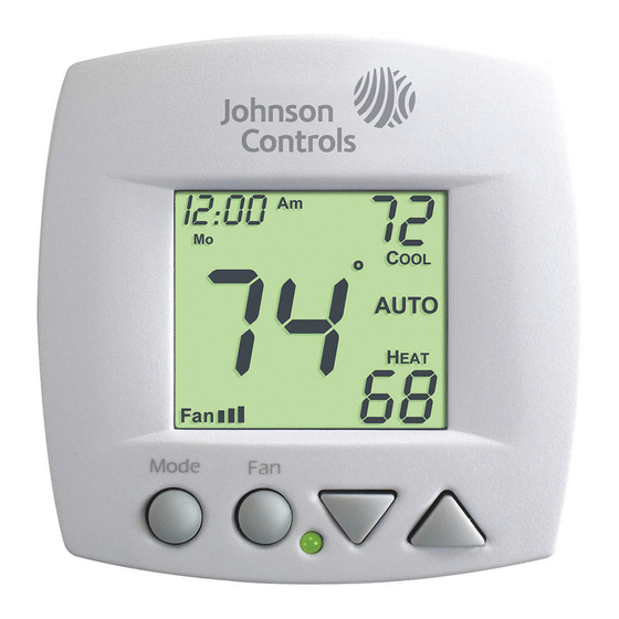
model T701DFN-1
Fan Coil
Thermostat
Remote sensor ready
Self-prompting adjustment
Auto 2-pipe changeover
when used with accessory
changeover sensor
Dry contact equipped
Backlit display
TM
One For All
works with
most all fan coil systems
Electric heat ready
Non-volatile memory
Dual setpoint with
adjustable deadband
Keypad lockout
Configurable display
Display either F or C
Terminals on backplate
Advertisement

Related Manuals for Johnson Controls T701DFN-1


Summary of Contents for Johnson Controls T701DFN-1
-
Page 1: Fan Coil
T701DFN-1 Fan Coil Thermostat 2 or 4 pipe systems Remote sensor ready Non-Programmable Self-prompting adjustment Thermostat Auto 2-pipe changeover when used with accessory changeover sensor Dry contact equipped Backlit display One For All works with most all fan coil systems... -
Page 2: Table Of Contents
IMPORTANT: The T701DFN-1 and T701DFP-1 Series Thermostat IMPORTANT: The T701DFN-1 and T701DFP-1 Series Thermostat Controllers are intended to provide an input to equipment under Controllers are intended to provide an input to equipment under normal operating conditions. -
Page 3: Step #1: Preparation
STEP #1 PREPARATION Proper installation of the thermostat will be accomplished by following these step by step instructions. If you are unsure about any of these steps, call a qualified technician for assistance. Assemble tools. Drill with 3/16 inch Drill Bit Flat Blade (when not Wire cutter... -
Page 4: Step #2 Applications
STEP #2 APPLICATIONS New Applications Follow the thermostat and E-M (Electro-Mechanical) wiring diagrams supplied with the submittal package, and afixed to the fan coil unit enclosure. Go to pages 6 through 10 for instructions to test operation for the available applications. Existing Applications Remove the cover of the old thermostat. -
Page 5: Step #3 Wire Connections
STEP #3 WIRE CONNECTIONS If the terminal designations on your old thermostat do not match those on the new thermostat, refer to the chart below. 4-PIPE SYSTEMS Wire from the Install on the old thermostat Function new thermostat terminal marked terminal marked Y1, Y or C Cooling... - Page 6 STEP #3 WIRE CONNECTIONS If the terminal designations on your old thermostat do not match those on the new thermostat, refer to the chart below. 2-PIPE SYSTEMS Wire from the Install on the old thermostat Function new thermostat terminal marked terminal marked Y1, Y or C Water Valve...
-
Page 7: Step #4 Test Operation
STEP #4 TEST OPERATION 4-PIPE SYSTEM Turn the power on to the Fan Coil Unit. Press the MODE button repeatedly until the HEAT icon appears on the display. Press the UP or DOWN buttons until the set temperature is 10 degrees above room temperature. - Page 8 STEP #4 TEST OPERATION 2-PIPE, CHANGEOVER SENSOR, NO STRIP HEAT Turn the power on to the Fan Coil Unit and confirm that the thermostat is programmed correctly in setup steps #3 and #4 on page 11 of the Owner’s Manual. If hot water is available, press the MODE button repeatedly until the HEAT icon appears on the display.
- Page 9 STEP #4 TEST OPERATION 2-PIPE, NO CHANGEOVER SENSOR Turn the power on to the Fan Coil Unit and confirm that the thermostat is programmed correctly in setup steps #3 and #4 on page 11 of the Owner’s Manual. If Heat Only, press the MODE button repeatedly until the HEAT icon appears on the display.
- Page 10 STEP #4 TEST OPERATION 2-PIPE, CHANGEOVER SENSOR, WITH STRIP HEAT Turn the power on to the Fan Coil Unit and confirm that the thermostat is programmed correctly in setup steps #3 and #4 on page 11 of the Owner’s Manual. If hot water is available, press the MODE button repeatedly until the HEAT icon appears on the display.
- Page 11 STEP #4 TEST OPERATION 2-PIPE, CHANGEOVER SENSOR, WITH STRIP HEAT Press the UP button until the setpoint is equal to the room temperature. Press the Fan button repeatedly until a single bar appears next to the Fan icon. Confirm the fan is running on low speed.
-
Page 12: Troubleshooting
TROUBLESHOOTING SYMPTOM: The fan will not run in all three speeds or switches speeds in an improper order. CAUSE: Incorrect wiring between the thermostat and the relay board, or between the relay board and the fan wires. REMEDY: Recheck the wiring (G=low speed, G2=medium speed, G3=high speed). - Page 13 TROUBLESHOOTING SYMPTOM: The thermostat displays large set- point digits instead of the room temperature. CAUSE: The thermostat has been programmed to display Single Setpoint. REMEDY: Program the thermostat to display Dual Setpoint (step #2, page 10 of the Owner’s Manual). SYMPTOM: The thermostat display is stuck in Unoccupied.
- Page 14 TROUBLESHOOTING SYMPTOM: The thermostat will only allow Heat or Off in 2-pipe installations, even though chilled water is available. CAUSE: Faulty, improperly wired, or improperly installed H2O changeover sensor. REMEDY: Confirm proper wiring of the change- over sensor (between R and H2O). Confirm proper placement of the sensor (good mechanical coupling for temperature transfer).
-
Page 15: Sample Wiring Diagram
SAMPLE WIRING DIAGRAM 2-Pipe, Low Voltage Valve, H2O Changeover Sensor Duct Sensor Important Note: If a Duct sensor is conn- SEN-700-1 ected to this thermostat it is suggested that the WHITE fan be programmed for BLACK continuous operation. Thermostat *NOTE: R wire from sensors should be connected as close as possible to thermostat terminal plate. - Page 16 TECHNICAL SPECIFICATIONS T701 Series Thermostat Controllers Power Requirements 20 - 30 VAC 50/60 Hz, 3 VA @ 24V nominal. Output Rating 0.4A max, 0.01A min, 3A inrush, 20 - 30 VAC (fan or valve outputs) Digital Inputs voltage free contacts, closed to signal CHILLED water supply voltage free contacts, closed to alter setpoints Local Temperature solid state temperature sensor, 10 mV / degF...
Need help?
Do you have a question about the T701DFN-1 and is the answer not in the manual?
Questions and answers