Table of Contents
Advertisement
Advertisement
Table of Contents

Related Manuals for OCEANAIRE Polaris Series


Summary of Contents for OCEANAIRE Polaris Series
- Page 1 polarismancover...
-
Page 2: General Description
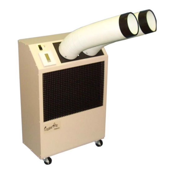
GENERAL DESCRIPTION POLARIS SERIES Air Conditioners are designed for applications where outside air is not available and spot cooling or air conditioning is needed. The cord connected Polaris Models range from 10500 BTU/HR to 60100 BTU/HR floor mount configuration to satisfy any space requirements. All models are provided with casters for portability. -
Page 3: Capacity Selection
NOMENCLATURE P WC 24 1 2 PORTABLE VOLTAGE WATER-COOLED SINGLE PHASE CAPACITY SELECTION CAPACITY SELECTION NUMBER CODE 10..10500 BTU/HR 12..13780 BTU/HR 18..18840 BTU/HR 24..23950 BTU/HR 36..36100 BTU/HR 60……..60100 BTU/HR polarismanpg2... - Page 4 PWC1011 PWC1211 PWC1811 PWC2412 PWC3612 PWC3632 PWC6012 PWC6032 PWC6034 MODEL Nominal Cooling Capacity 1 10,500 13,780 18,840 23,950 36,100 36,100 60,100 60,100 60,100 208/230/3 208/230/1 208/230/3 460/3 Voltage 115/60/1 or 208/230/1 208-230/60/1 Unit Amps 7.7/3.9 10.5/5.3 12.0/6.2 13.0 20.7 14.8 Unit Watts 1050 1400...
-
Page 5: Standard Features
ATTRACTIVE CABINET The Polaris Series cabinet is constructed of 18 gauge cold rolled steel with a platinum polyester powder coated finish that will compliment any decor. The entire cabinet is insulated with a sound absorbant insu- lation for cool, quiet comfort. The basepan is 14 gauge galvanized steel and remains dry and free from odor and fungal growth. -
Page 6: Condenser Coil
Just pull the grille out and remove the filter. SERVICE CORD All Polaris Series units are equipped with the standard ten foot long service cord with UL listed plug con- figurations. The following page contains Oceanaire plug configurations for all units. - Page 7 UNIT/MODEL PLUG CONFIGURATION RECEPTACLE 115 VOLT PWC1011, PWC1211, PWC1811 15A-125 VOLT PAC1011, PAC1211, OWC1211, NEMA 5-15P NEMA-5-15R OWC1811, OAC1211, OACH1211 115 VOLT 20A-125 VOLT PAC18, OAC18, OACH18 NEMA 5-20R NEMA 5-20P 208/230 VOLT SINGLE PHASE PAC1012,1212,1812,2412 OAC1212,1812,2412 20A-250 VOLT NEMA 6-20R OACH1212,1812,2412 NEMA 6-20P PWC1012,1212,1812,2412,3612...
-
Page 8: Optional Features
OPTIONAL FEATURES HOSE KIT 10, 25, and 40 foot hose kits with flare connectors to match fittings on units, banded 3-in-one design for easy and convenient installation, are available. When using these hoses in applications with water pres- sures exceeding 50 PSIG, a water pressure reducing valve must be installed in the water supply line prior to the hose kit;... -
Page 9: Unit Construction
UNIT CONSTRUCTION Evaporator blower Evaporator blower motor Thermostat Evaporator coil Fan motor capacitor High Pressure Switch Evaporator drain Condenser Water Outlet Drain hose Condenser Condensate pump Condenser Water Inlet Compressor Condensate Outlet Dry Base pan Casters Electrical Box Water valve polarismanpg8... -
Page 10: Electrical Requirements
INSTALLATION INSTRUCTIONS ELECTRICAL REQUIREMENTS Adhere to the data plate on the back of the unit and make certain that the proper power is used. Refer to the "Specifications" section for voltage and fuse requirements. Make sure that proper wall outlets and re- ceptacles are used as described in "Standard Features"... - Page 11 PRACTICAL INSTALLATION Proper installation can be achieved by following these simple steps: 1. Turn off cold water supply. 2. Install “T” between faucet of cold water line and supply valve. 3. Connect shut-off valve to “T” branch. 4. Insert a 3/8 pipe nipple in discharge end of water shut-off valve. 5.
- Page 12 ACCESSORIES Model Round Fits Fits Fits Fits Fits Fits Evaporator Duct Grille Plenum Size 10 inch EP-10 Evaporator 12 inch Plenum EP-12 16 Inch EP-16 Evaporator plenum at- Maximum taches to unit Equivalent Feet in place of standard (ESP) (.15) (.15) (.25) (.25)
-
Page 13: Cooling Cycle
FAN ONLY Plug unit in and push FAN button once. This turns the evaporator fan blower on. To turn the blower off, push the FAN button once again. This turns the fan blower off. To change fan speeds, push the fan speed rocker switch up for high speed or down for low speed. COOLING CYCLE To operate unit for cooling, push MODE button to dis- play COOL in the window. - Page 14 REPLACEMENT PROCEDURE FOR PARTS A. FAN MOTOR 1. Remove cabinet's left-hand (when looking at the front of the unit) side panel. 2. Disconnect motor wires from evaporator contactor and fan speed rocker switch. 3. Remove screws securing motor and O-ring to blower housing. All screws are external and visible. 4.
-
Page 15: Troubleshooting Guide
4. Disconnect valve from "water in" line. 5. Install new valve, reversing the procedure. F. HIGH PRESSURE CONTROL 1. Follow the first two steps in "E". 2. Remove two screws that retain switch to right side panel. 3. Disconnect wire leads from compressor contactor and condensate pump safety switch. 4. - Page 16 2. (CAUSE) Thermostat (REMEDY) Examine the control unit for loose wires. Tighten any loose connections. Wait 4-minutes before re-start. 3. (REASON) High Pressure Control cutting turning unit off (FIXING) Check for loose wire connections, broken or burned contacts. If switch is defective, replace. Not enough water flow to unit or water is too warm.
- Page 17 PROBLEM: INSUFFICIENT COOLING 1. (CAUSE) Insufficient air flow through evaporator coil due to: A. Dirty air filter in unit B. Dirty evaporator coil C. Ice on evaporator coil D. Obstructed air intake (REMEDY) Correct as noted: A. Clean filter (see "Preventive Maintenance" section of this manual) B.
-
Page 18: Preventive Maintenance
(REMEDY) Replace batteries. PREVENTIVE MAINTENANCE Polaris Series air conditioners are designed to last a long time and to give maximum performance and reliability with minimum maintenance. To prolong the life of the unit, regular maintenance must be performed as specified below: 1. -
Page 19: Condensate Pump
2. FILTER A clogged filter will cause the unit to operate at greatly reduced efficiencies. We recommend that the filter be inspected on a regular bases every six weeks or more often depending on the environment. The foam filter is located behind the return air grille and can be easily removed by pulling the grille out. The filter must be washed periodically as needed by placing it in a dishwasher or soaking it in a solution of warm water and detergent for 10 minutes. -
Page 20: Piping Schematic
PIPING SCHEMATIC WATER COOLED AIR-CONDITIONER polarismanpg19... - Page 21 May 1, 2002 HIGH-LO EVAPORATOR FAN SWITCH THERMOSTAT COOLING ONLY HIGH EVAPORATOR MOTOR TERMINAL BLOCK EVAPORATOR MOTOR CONTACTOR HARD START STANDARD ON ONLY PWC1811 24 Volt Coil COMPRESSOR CONTACTOR 24 Volt 24 Volt Coil 120 or 230 Volt TRANSFORMER COMPRESSOR TERMINAL BLOCK SAFETY...
- Page 22 May 1, 2002 JUMPER HI-LO FAN SWITCH COOLING HIGH THERMOSTAT TERMINAL BLOCK VOLT EVAP 24v CONTROL TRANSFORMER MOTOR 230 VOLT VOLT VOLT 230v POWER TRANSFORMER COMPRESSOR 24 Volt Coil EVAP MOTOR CONTACTOR VOLT 24 Volt Coil COMPRESSOR CONTACTOR HIGH PRESSURE SWITCH TERMINAL BLOCK N.C.
- Page 23 May 1, 2002 HIGH-LO EVAPORATOR FAN SWITCH THERMOSTAT COOLING ONLY HIGH EVAPORATOR MOTOR TERMINAL BLOCK EVAPORATOR MOTOR CONTACTOR 24 Volt Coil COMPRESSOR CONTACTOR 24 Volt 24 Volt Coil TRANSFORMER 230 Volt COMPRESSOR SAFETY SWITCH HIGH PRESSURE SWITCH CONDENSATE PUMP 230 VOLT RED LIGHT ON CONTROL PANEL 208/230/3/60...
- Page 24 The Manufacturer (OceanAire, Inc.) warrants to the his limited warranty is conditional upon: original owner that the Product will be free from defects in material or workmanship for a period not to exceed (a) shipment, to the Manufacturer, one (1) year from date of installation. If upon of that part of the Product thought examination by the Manufacturer the Product is shown to be defective.
Need help?
Do you have a question about the Polaris Series and is the answer not in the manual?
Questions and answers