Bryant HRVBBLHA Installation Instructions Manual
Heat recovery ventilator
Hide thumbs
Also See for HRVBBLHA:
- Product data (10 pages) ,
- Product data (11 pages) ,
- Installation instructions manual (19 pages)
Table of Contents
Advertisement
HRVBBLHA
HRVBBSVU
HRVBBLVU
HEAT RECOVERY VENTILATOR
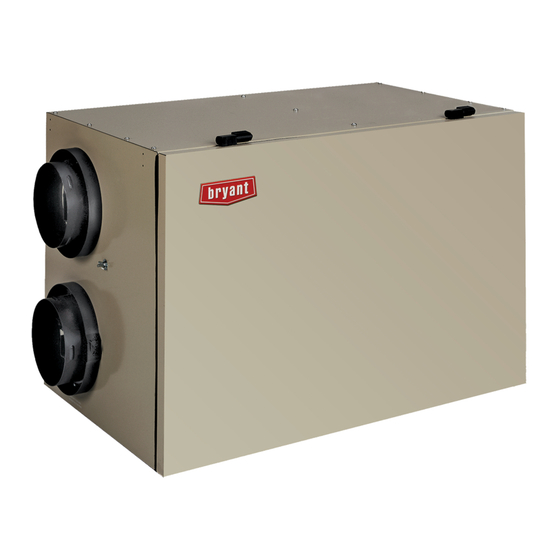
Fig. 1 --- HRVBBLHA Conventional Unit
Fig. 2 --- HRVBBSVU Compact Unit
Fig. 3 --- HRVBBLVU High Efficiency Unit
Note: Read the entire instruction manual before starting the
installation.
SAFETY CONSIDERATIONS
Installation and servicing of this equipment can be
hazardous due to mechanical and electrical components.
Installation Instructions
A05260
A92268
A92377
Only trained and qualified personnel should install, repair,
or service this equipment.
Untrained personnel can perform basic maintenance
functions such as cleaning and replacing air filters. All other
operations
must
be
personnel. When working on this equipment, observe
precautions in the literature, on tags, and on labels
attached to or shipped with the unit and other safety
precautions that may apply.
Follow all safety codes. Installation must be in compliance
with local and national building codes. Wear safety glasses,
protective clothing, and work gloves. Have fire extinguisher
available. Read these instructions thoroughly and follow all
warnings or cautions included in literature and attached to
the unit.
Recognize safety information. This is the safety --- alert symbol
When you see this symbol on the unit and in instructions or
manuals,
be
alert
injury.Understand
these
WARNING, and CAUTION. These words are used with the
safety ---alert symbol. DANGER identifies the most serious
hazards which will result in severe personal injury or death.
WARNING signifies hazards which could result in personal
injury or death. CAUTION is used to identify unsafe
practices which may result in minor personal injury or
product and property damage. NOTE is used to highlight
suggestions which will result in enhanced installation,
reliability, or operation.
INTRODUCTION
The Heat Recovery Ventilator (HRV) is used to exchange
indoor stale air with outside fresh air. The HRV unit is
equipped with a special heat recovery core which transfers
sensible heat between the fresh incoming air and stale
exhaust air.
It is required to locate the HRV in a conditioned space.
Special attention should be given to condensate drain, duct
application, balancing HRV, and locating unit for easy
access and routine maintenance. The cross---flow design
core allows entering and leaving air streams to transfer heat
energy without mixing (See Fig. 14, and 17 ---24).
Step 1.—Inspect Equipment
Move carton to final installation location. Remove HRV from
carton taking care not to damage unit. Remove all
packaging and inspect unit for damage. Remove parts bag
from inside unit. File claim with shipping company if
shipment is damaged or incomplete. Check to make sure
HRV unit matches Fig. 1 through 3 and 4 through 6.
1
performed
by
trained
to
the
potential
for
personal
signal
words;
DANGER,
LOCATION
service
!
!
Advertisement
Table of Contents

Related Manuals for Bryant HRVBBLHA


Summary of Contents for Bryant HRVBBLHA
-
Page 1: Installation Instructions
Follow all safety codes. Installation must be in compliance A05260 with local and national building codes. Wear safety glasses, Fig. 1 --- HRVBBLHA Conventional Unit protective clothing, and work gloves. Have fire extinguisher available. Read these instructions thoroughly and follow all warnings or cautions included in literature and attached to the unit. -
Page 2: Component Description
Fig. 6 --- HRVBBLVU Compact High ---Efficiency Unit COMPONENT DESCRIPTION The following listed items are components of HRVBBSVU The following listed items are components of HRVBBLHA and HRVBBLVU (See Fig. 5 and 6). (See Fig. 4). 1. Stale ---air return from building connected to return ---air 1. -
Page 3: Unit Installation
Step 2.—Select Location The HRV should be located in a conditioned space and WARNING: CARBON MONOXIDE POISONING HAZARD in close proximity to a fused power source. It should be easily accessible for routine maintenance. Failure to follow this warning could result in personal injury or death. -
Page 4: Exhaust Hood
HRVBBSVU and HRVBBLVU units. The balancing dampers insulated (See Fig. 9). This can act as a silencer when are provided in the HRVBBLHA units (see balancing HRV connecting ducts to return ---air duct system. This should section). Make sure both balancing dampers are left in fully eliminate transmission of noise or vibration from unit to open position before connecting the ducts to these ports. -
Page 5: Wall Control
Step 5.—Condensate Drain To connect condensate drain, proceed as follows: 1. Insert sleeved grommets into bottom of unit using the gasket washer and nut (See Fig. 10). 2. Cut two sections of plastic tubing, about 12” long and attach them to each drain. 3. - Page 6 operation are fully functional. See Table 3 indicating standard control operation. OPERATING THE HRV WITH THE EVOLUTION CONTROL 1. With switch off, ERV/HRV is inoperative and the LED is The ventilator has four settings in heating mode and three out. settings in cooling mode.
-
Page 7: Operation
Table 1—Basic Control MODE OPERATION DAMPER POSITION FAN SPEED Closed to outside Air exchange with outside Open to outside High Air exchange with outside Open to outside High Table 2—OneTouch Push Button Control MODE OPERATION DAMPER POSITION FAN SPEED Closed to outside Air exchange with outside Open to outside Intermittent... -
Page 8: Electrical Connections
ELECTRICAL CONNECTIONS is not, interlock relay will energize and make R and G at indoor equipment. This will ensure fresh air distribution 1. 115 ---vac Wiring throughout the building via the central duct system. The HRV operates on 115vac. It comes with a power cord 1. - Page 9 STRIP YELLOW – (J3-3) INDICATOR TERMINAL STRIP RED – (J3-5) SWITCH TERMINAL STRIP (OL) BACK OF PUSH BUTTON SWITCH A98386 Fig. 13 --- Push Button Timer Wiring Layout Fresh air flow Exhaust Air Flow A05333 Fig. 14 --- Balancing HRVBBLHA...
-
Page 10: Right Side View
Note: Temporary flow collars are not needed with the new Step 2.—Flow Collar HRVBBLHA models since the air flow pressure taps are Flow collars are temporary and should be installed as close incorporated in the access door (See Fig. 14). -
Page 11: Fresh Air
Fig. 16 --- Magnehelic Gage FRESH AIR FROM OUTSIDE STALE AIR TO OUTSIDE STALE AIR FROM BUILDING A05352 Fig. 17 --- HRVBBLHA and HRVBBSVU Cross Flow FRESH AIR TO BUILDING A98404 Fig. 19 --- HRVBBLVU Counterflow FILTERED AIR STALE AIR FRESH AIR... - Page 12 FILTERED AIR TO BUILDING FRESH AIR FRESH AIR STALE AIR TO BUILDING FROM OUTSIDE FROM BUILDING STALE AIR STALE AIR FROM BUILDING TO OUTSIDE A92382 A92383 Fig. 23 --- HRVBBSVU Airflow During Fig. 21 --- HRVBBSVU Airflow During Air Exchange Recirculation and Defrost FRESH AIR STALE AIR...
-
Page 13: Ventilation Evaluation
WASH- WASH- WASH- LAUNDARY ROOM ROOM BEDROOM ROOM KITCHEN ROOM MASTER LIVING ROOM BEDROOM BEDROOM DINING ROOM FAMILY ROOM BEDROOM 1320 sq ft (125 sq m) 1320 sq ft (125 sq m) BASEMENT 1320 sq ft (125 sq m) A98388 Fig. -
Page 14: Care And Maintenance
Step 5.—Low ---Speed Air Exchange use. This will ensure maximum efficiency of the plastic partitions within the core. When low ---speed air exchange occurs, K1 Relay is Allow heat recovery core to soak for 3 hours in a solution of energized which closes the contacts. -
Page 15: High Speed
Table 6—Troubleshooting Chart SYMPTOMS CAUSES SOLUTIONS Continuous exchange mode Use Intermittent Mode Air too humid used in small houses Check humidity level settings Unit will operate when not in defrost mode. Defrost condition is in effect Outdoor temperature is below 23°F Defrost cycle is based on outdoor ambient (See Table 10) Test wall control Unit not responding to wall control... -
Page 16: Advanced Debugging
Table 8—Factory Set Blower Connection High or Low Safety Feature Speed This new control has an added safety feature. If microprocessor does not detect the thermistor or detects a Control Main Electrical Blower Speed short circuit, unit will automatically go into a 6 minute Module Harness Cable Wire... - Page 17 Table 13—Jumper Locations JUMPER TABLE MODEL JU1A JU1B JU1C JU1D JU1E JU1F JU1G HRVBBLHA1150 HRVBBLHA1250 HRVBBSVU1150 HRVBBSVU1250 HRVBBLVU1150 HRVBBLVU1200 HRVBBLVU1330 CASE 2 7. Error Signaling User changes the mode but, HRV does not respond. All indicators flash at a rate of about once every 8 sec. Check Two types of error can be signaled by the wall control all wires to wall control particularly green wire.
-
Page 23: Service Training
SERVICE TRAINING Packaged Service Training programs are an excellent way to increase your knowledge of the equipment discussed in this manual, including: S Unit Familiarization S Maintenance S Installation Overview S Operating Sequence A large selection of product, theory, and skills programs is available, using popular video---based formats and materials. - Page 24 Catalog No:II HRV--- 71--- 4 Printed in U.S.A. edition date: 11/05 Copyright 2005 Carrier Corp. S 7310 W. Morris St. S Indianapolis, IN 46231 Replaces: II HRV--- 71--- 3 Manufacturer reserves the right to change, at any time, specifications and designs without notice and without obligations.
Need help?
Do you have a question about the HRVBBLHA and is the answer not in the manual?
Questions and answers