
Subscribe to Our Youtube Channel
Related Manuals for ATV IPC560TDN


Summary of Contents for ATV IPC560TDN
-
Page 1: Box Camera
INSTRUCTION MANUAL NETWORK BOX CAMERA Please read this manual thoroughly before use, and keep it handy for future reference. - Page 2 WARNING TO REDUCE THE RISK OF FIRE OR ELECTRIC SHOCK, DO NOT EXPOSE THIS PROCUCT TO RAIN OR MOISTURE. DO NOT INSERT ANY METALLIC OBJECT THROUGH THE VENTILATION GRILLS OR OTHER OPENNINGS ON THE EQUIPMENT. CAUTION The lightning flash with arrowhead symbol, within an equilateral triangle, is intended to alert the user to the presence of uninsulated "dangerous voltage"...
-
Page 3: Fcc Compliance Statement
FCC COMPLIANCE STATEMENT INFORMATION TO THE USER : THIS EQUIPMENT HAS BEEN TESTED AND FOUND TO COMPLY WITH THE LIMITS FOR A CLASS A DIGITAL DEVICE, PURSUANT TO PART 15 OF THE FCC RULES. THESE LIMITS ARE DESIGNED TO PROVIDE REASONABLE PROTECTION AGAINST HARMFUL INTERFERENCE WHEN THE EQUIPMENT IS OPERATED IN A COMMERCIAL ENVIRONMENT. -
Page 4: Important Safety Instructions
IMPORTANT SAFETY INSTRUCTIONS Read these instructions. Keep these instructions. Heed all warnings. Follow all instructions. Do not use this apparatus near water. Clean only with dry cloth. Do not block any ventilation openings. Install in accordance with the manufacturer’s instructions. Do not install near any heat sources such as radiators, heat registers, stoves, or other apparatus (including amplifiers) that produce heat. -
Page 5: Table Of Contents
Table of Contents 1. Product Description…………………………………………………………………………………………………6 2. Installation……………………………………………………......…………..………………13 3. Operation…………………………………………………………………………………………………………….15 3.1 Access from a browser …………………………………………………………………………………..15 3.2 Access from the internet ………………………………………………………………………………..16 3.3 Setting the admin password over a secure connection…………………………….…….…16 3.4 Live View Page ………………………………………………………………………………………………17 3.5 Camera Setup (Analog)……………………………………………………………………………….….19 3.5.1 Settings…………………………………………………………………………………………………..19 3.6 Network Camera Setup………………………………………………………………………………...25 3.6.1 Basic Configuration…………………………………………………………………….…………...25... -
Page 6: Product Description
1. Product Description This manual applies to the IPC560TDN network camera. The Network Camera supports the network service for a sensor image with progressive scan, which can be monitored on a real-time screen regardless of distances and locations. By using its dedicated program, many users are able to have an access to the Network Camera at once or a single user can monitor various network cameras at the same time. -
Page 7: Key Features
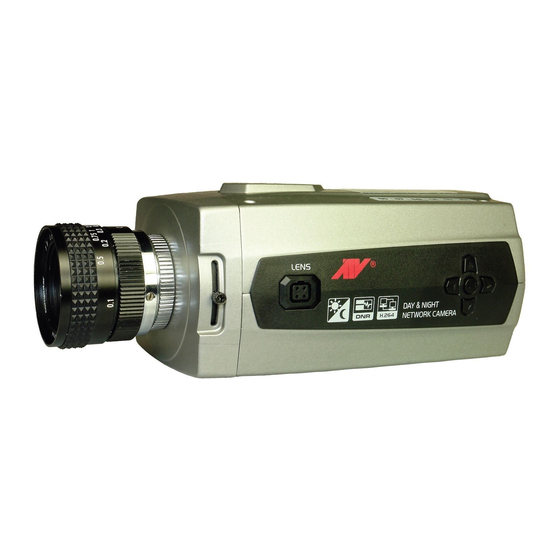
Key Features • Brilliant video quality The Network Camera offers the highly efficient H.264 video compression, which drastically reduces bandwidth and storage requirements without compromising image quality. Motion JPEG is also supported for increased flexibility. • Dual streams The Network Camera can deliver dual video streams simultaneously at full frame rate in all resolutions up to D1 (720x480 in NTSC, 720x576 in PAL) using Motion JPEG and H.264 (or MPEG-4). - Page 8 Overview • Front View Function Back-focus adjusting locking screw Auto IRIS lens connector Setup Buttons • Rear View Function Description Power adaptor terminal Main Power, 2pin terminal, DC12V/AC24V max. 6.5Watt. RS485 terminal Connects PTZ or PT device. Power Indicator Indicates power input. Status Indicator Indicates camera status.
- Page 9 • LED Indicators Color Indication Steady for connection to a 100 Mbit/s network. Flashes for Green network activity. Network Steady for connection to 10 Mbit/s network. Flashes for Amber network activity. Unlit No network connection. Status Steady red for failed upgrade or booting. Steady green for normal operation or booting.
- Page 10 5. Adjust the focus ring on the lens for an optimum picture. If a picture is not visible, set the lens for proper exposure by adjusting the ALC (Automatic Level Control) and the level on the lens. The ALC setting can range between AVG (average) or PK (peak). A midrange setting is appropriate for most applications.
- Page 11 3. Plug the connector into the auto iris jack on the side of the camera. The connector is polarized and can only inserted into the jack one way. 4. Apply power to the camera. 5. The OSD AE menu in the lens select should be in the "DC↓". 6.
- Page 12 6. Tighten the back focus lock screw. 7. Fine tune the focus with the focus ring on the lens. 8. Remove the welder's glass from in front of the lens. 9. Adjust the iris of the lens for the best picture quality. •...
-
Page 13: Installation
2. Installation For the operation of the Network Camera, it is necessary to connect a network cable for data transmission, power connection from power adapter. Depending on operation methods, it is possible to connect an alarm cable or audio cable additionally. For its fixation on different locations, please consult with an installer. - Page 14 4. Select Assign IP. You cam see a Assign IP window. Enter the required IP address. Note: For more information, refer to the SmartManager User’s Manual.
-
Page 15: Operation
3. Operation The Network Camera can be used with Windows operating system and browsers. The recommended browsers are Internet Explorer, Safari, Firefox, Opera and Google Chrome with Windows. Note: To view streaming video in Microsoft Internet Explorer, set your browser to allow ActiveX controls. -
Page 16: Access From The Internet
3.2. Access from the internet Access from the internet Once connected, the Network Camera is accessible on your local network (LAN). To access the network camera from the Internet you must configure your broadband router to allow incoming data traffic to the network camera. To do this, enable the NAT-traversal feature, which will attempt to automatically configure the router to allow access to the network camera. -
Page 17: Live View Page
3.4 Live View Page The live view page comes in eight screen modes: 704x480(576), 704x240(288), 352x240(288), 176x120(144), 640x480, 320x240, 160x120. Users allowed to select the most suitable one out of those modes. Please, adjust the mode in accordance with your PC specifications and monitoring purposes. - Page 18 screen view. The Manual Trigger button activates a pop-up window to manually start or stop the event. The Camera Menu button activates a pop-up window for camera menu control. The PTZ button activates a pop-up window for Pan, Tilt and Zoom control. Use this scale to control the volume of the speakers.
-
Page 19: Camera Setup (Analog)
3.5 Camera Setup (Analog) 3.5.1 Settings Settings can be made using the 5 buttons located on the back of the camera. ▶ Structure of menu setup... - Page 20 ▶ LENS (Selection) This function is used to adjust the brightness of the screen. 1. When the SETUP menu is displayed on the screen, please position the arrow to point to LENS by using the UP and DOWN buttons. 2. Please select the type of the lens you wish to use by pressing the LEFT or RIGHT button.
- Page 21 [BLC MODE] ▶ WHITE BAL The Screen color can be adjusted by using the WHITE BALANCE function. -. AWB: Wide range auto white balance mode. -. AWC => SET: Please press the ENTER button while the camera is directed at a piece of while paper to obtain the optimum state under current illumination.
- Page 22 ▶ DAY NIGHT The DAY/NIGHT menu is used to configure the day and night related setting for this camera. This camera can turn the IR(Infrared) filter on or off. -. Mode: AUTO/EXT/BW/COLOR [DAY/NIGHT AUTO MODE] [DAY/NIGHT B/W MODE] ▶ 3DNR(Digital Noise Reduction) You can configure the DNR(Digital Noise Reduction) related settings.
- Page 23 ▶ SPECIAL 1. CAM TITLE -. A CAM TITLE : Camera Title -. B 0123456789ABCD : Character Table EFGHIJKLMNOPQRSTUVWXYZ ▶→←↑↓()−_▐ /=&:~,” -. C ←→CLR POS END : ←, Move to left :→, Move to right : CLR, Erase all characters : POS, Move the position of title : END, Save and End 2.
- Page 24 4. PRIVACY -. AREA SELECT: Select MASK area number. -. AREA DISPLAY: Select MASK ON/OFF. -. LEFT/RIGHT: Adjust the location of the MASK area with boundary LEFT and RIGHT. -. WIDTH: Adjust width of MASK area. -. TOP/BOTTOM: Adjust the location of the MASK area with boundary TOP and BOTTOM. -.
-
Page 25: Network Camera Setup
3.6 Network Camera Setup This section describes how to configure the network camera, and is intended for product Administrators, who have unrestricted access to all the Setup tools; and Operators, who have access to the settings for Basic, Live View, Video & Image, Audio, Event, and System Configuration. -
Page 26: Network
The user list displays the authorized users and user groups (levels): User Group Authority Provides the lowest level of access, which only allows access to the Guest Live View page. An operator can view the Live View page, create and modify Operator events, and adjust certain other settings. -
Page 27: Video & Image
• Obtain IP address via DHCP - Dynamic Host Configuration Protocol (DHCP) is a protocol that lets network administrators centrally manage and automate the assignment of IP addresses on a network. DHCP is enabled by default. Although a DHCP server is mostly used to set an IP address dynamically, it is also possible to use it to set a static, known IP address for a particular MAC address. - Page 28 • Video Setting -. Codec The codec settings are separated into MPEG4 and H.264. H.264 is a lso known as MPEG-4 Part 10. This is the new generation compression standard for digital video. This function offers higher video resolution than Motion JPEG or MPEG-4 at the same bit rate and bandwidth, or the same quality video at a lower bit rate.
- Page 29 The bit rate can be set as Variable Bit Rate (VBR) or Constant Bit Rate (CBR). VBR adjusts the bit rate according to the image complexity, using up bandwidth for increased activity in the image, and less for lower activity in the monitored area. CBR allows you to set a fixed target bitrate that consumes a predictable amount of bandwidth.
-
Page 30: Audio
-. JPEG quality Select the picture quality. If users want to have a high quality of fast image one by one, please decrease the value. For the purpose of general monitoring, please do not change a basic value. Such act may cause a problem to the system performance. When satisfied with the settings, click Save, or click Reset to revert to previously saved settings. - Page 31 -. Sound bitrate Depending on the selected encoding, set the desired audio quality (bitrate). The settings affect the available bandwidth and the required audio quality. • Audio Input Audio from an external line source can be connected to the terminal I/O of the network camera.
-
Page 32: Date & Time
3.6.1.5 Date & Time • Current Server Time It displays the current date and time (24h clock). The time can be displayed in 12h clock format in the overlay (see below). • New Server Time Select your time zone from the drop-down list. If you want the server clock to automatically adjust for daylight savings time, select the “Automatically adjustment for daylight saving time changes”. -
Page 33: Video & Image
3.6.2 Video & Image ▼ Basic Refer to “3.6.1.3 Video & Image” for more details. - Page 34 ▼ Privacy Masking - Basic The privacy masking function allows you to mask parts of the video image to be transmitted. You can set up to eight privacy masks and the color of privacy masks is black. The privacy masks are configured by Mask windows. Each window can be selected by clicking with the mouse.
- Page 35 ▼ Webcasting – Channel1 The network camera can stream live video to a website. Copy HTML code generated on the screen and paste it in page code of the website you want to display live video. Note: To use webcasting service, the Enable Anonymous viewer login option must be checked.
-
Page 36: Audio
3.6.3 Audio Refer to “3.5.1.4 Audio” for more details. -
Page 37: Event
3.6.4 Event 3.6.4.1 Event-In ▼ On Boot This is used to trigger the event every time the Network Camera starts. Select “Enable” to activate the On Boot event. - Page 38 ▼ Alarm In Select “Enable” to activate the alarm event. The network camera supports 1 alarm input port. -. Type - Choose the type of alarm you wish to use from the drop-down list. -. Dwell Time - Set the dwell time of an event lasts for the specified dwell time from the point of detection of an alarm input.
- Page 39 ▼ Manual Trigger This option makes use of the manual trigger button provided on the live view page, which is used to start or stop the event type manually. Alternatively the event can be triggered via the product's API (Application Programming Interface).
- Page 40 ▼ Motion Motion detection is used to generate an alarm whenever movement occurs (or stops) in the video image. A total of 8 Motion and/or Mask windows can be created and configured. Motion is detected in defined Motion windows, which are placed in the video image to target specific areas.
- Page 41 To create a motion or mask window, follow steps: 1. Click the right button of mouse to see the mouse menu. 2. Select New Motion (or Mask) Window in the mouse menu. 3. Click and drag mouse to designate a motion area. •...
-
Page 42: Event Out
3.6.4.2 Event-Out ▼ SMTP(E-Mail) The Network Camera can be configured to send event and error email messages via SMTP (Simple Mail Transfer Protocol). • SMTP(E-Mail) Setting Select “Enable” to activate the SMTP operation. -. Mail Server / Port - Enter the host names (or IP addresses) and port numbers for your mail server in the fields provided, to enable the sending of notifications and image email messages from the camera to predefined addresses via SMTP. - Page 43 To ensure that the login procedure is performed as securely as possible when using SMTP authentication, you must define the weakest authentication method allowed. -. Login Method - Set the Weakest method allowed to the highest/safest method supported by the mail server. The most secure method is listed in the drop-down list: Login / Plain •...
- Page 44 -. Remote directory - Specify the path to the directory where the uploaded images will be stored. If this directory does not already exist on the FTP server, there will be an error message when uploading. -. User name / Password - Provide your log-in information. •...
- Page 45 • HTTP Server Setting -. Name - The name of the HTTP event server. Use a descriptive name. -. URL - The network address to the server and the script that will handle the request. For example: http://192.168.12.244/cgi-bin/upload.cgi -. User name/Password - Provide your log-in information. •...
- Page 46 ▼ Audio Alert When the network camera detects an event, it can output a predefined audio data to external speaker. Check the box to enable the service. • Audio Alert Setting To use the audio alert with the network camera, an audio data file made by user must be uploaded from your PC.
- Page 47 Audio Recorder To use Audio Recorder tool to make an audio file for Audio Alert function, you must install the NCTitanium on the installation CD at first. Start the ARecorder program (All Programs>NCTitanium>Tools>ARecorder) in your PC and the main window will be displayed as below. The description of each button in the ARecorder window follows.
- Page 48 Caution: All parameters must be synchronized with ones in audio setting page of network devices for a proper operation.
- Page 49 ▼ PTZ Preset When the network camera detects an event, you can make a PTZ camera connected to its RS485 port to move to a predefined preset position. Check the box to enable the service and return to the Home position once the event has ended.
-
Page 50: Event Map
3.6.4.3 Event Map The event map allows you to change the settings and establish a schedule for each event trigger from the Network Camera. You can register the event map up to max. 15. Click Add button to make a new event map and you can see a popup window as below. -
Page 51: Device
• General Enter the name for a new event map. • Event In Select an event type in the drop down list. • Event Out -. E-mail: Select email addresses you want to send via email that an event has occurred. -. - Page 52 ▼ RS485 • RS485 settings -. Baud rate - Select a Baud Rate in the drop-down list. (Default 9600 bps) -. Data bits - Select Data Bits in the drop-down list. (Default None) -. Parity bits - Select Parity Bits in the drop-down list. (Default 8 bits) -.
-
Page 53: System
3.6.6 System 3.6.6.1 Information You can enter the system information. This page is very useful when you refer device information after installation. • Device Name Configuration Enter the device name. • Location Configuration Enter the location information. You can enter that by four. -
Page 54: Security
3.6.6.2 Security ▼ Users User access control is enabled by default, when the administrator sets the root password on first access. New users are authorized with user names and passwords, or the administrator can choose to allow anonymous viewer login to the Live View page, as described below: •... - Page 55 ▼ HTTPS For greater security, the Network Camera can be configured to use HTTPS (Hypertext Transfer Protocol over SSL (Secure Socket Layer)). That is, all communication that would otherwise go via HTTP will instead go via an encrypted HTTPS connection. •...
- Page 56 ▼ IP Filtering Checking the Enable IP address filtering box enables the IP address filtering function. Up to 256 IP address entries may be specified (a single entry can contain multiple IP addresses). Click the Add button to add new filtered addresses. When the IP address filter is enabled, addresses added to the list are set as allowed or denied addresses.
-
Page 57: Date & Time
3.6.6.3 Date & Time • Current Server Time It displays the current date and time (24h clock). The time can be displayed in 12h clock format in the overlay (see below). • New Server Time Select your time zone from the drop-down list. If you want the server clock to automatically adjust for daylight savings time, select “Automatically adjustment for daylight saving time changes”. -
Page 58: Network
3.6.6.4 Network Setting in regard to network can be executed. Settings for IP, DNS, Host Name, Port, and ARP/Ping can be established, along with setting for DDNS, uPnP, QoS, Zeroconfig, and Bonjour. - Page 59 ▼ Basic • IP Address Configuration: -. Obtain IP address via DHCP - Dynamic Host Configuration Protocol (DHCP) is a protocol that lets network administrators centrally manage and automate the assignment of IP addresses on a network. DHCP is enabled by default. Although a DHCP server is mostly used to set an IP address dynamically, it is also possible to use it to set a static, known IP address for a particular MAC address.
- Page 60 Leave disabled to prevent unintentional resetting of the IP address. ▼ DDNS • Internet DDNS(Dynamic Domain Name Service) When using the high-speed Internet with the telephone or cable network, users can operate the Network Camera even on the floating IP environment in which IPs are changed at every access.
- Page 61 ▼ RTP Have a setting for sending and receiving an audio or video on a real-time basis. These settings are the IP address, port number, and Time-To-Live value to use for the media stream(s) in multicast H.264 format. Only certain IP addresses and port numbers should be used for multicast streams.
- Page 62 ▼ UPnP The Network Camera includes support for UPnP™. UPnP™ is enabled by default, and the Network Camera then is automatically detected by operating systems and clients that support this protocol. Note: UPnP™ must be installed on your workstation if running Windows XP. To do this, open the Control Panel from the Start Menu and select Add/Remove Programs.
- Page 63 ▼ QoS Quality of Service (QoS) provides the means to guarantee a certain level of a specified resource to selected traffic on a network. Quality can be defined as a maintained level of bandwidth, low latency, and no packet losses. The main benefits of a QoS-aware network are: -.
- Page 64 • Auto Traffic Control Set a limitation on user network resources by designating the maximum bandwidth. -. Maximum bandwidth - In case of sharing other network programs or equipment, it is possible to set a limitation on the maximum bandwidth in the unit of Mbit/s or kbit/s. -.
- Page 65 • NAT traversal Settings -. Enable - when enabled, the network camera attempt to configure port mapping in a NAT router on your network, using UPnP™. Note that UPnP™ must be enabled in the Network Camera (see System>Network>UPnP). * automatic setting: The Network Camera automatically search for NAT routers on your network.
- Page 66 Zeroconfig Zeroconfig allows the network camera to create and assign IP address for network cameras and connect to a network automatically. Zero configuration networking (zeroconf), is a set of techniques that automatically creates a usable Internet Protocol (IP) network without manual operator intervention or special configuration servers.
-
Page 67: Language
Bonjour The network camera includes support for Bonjour. When enabled, the network camera is automatically detected by operating systems and clients that support this protocol. Note: Bonjour - Also known as zero-configuration networking, Bonjour enables devices to automatically discover each other on a network, without having to enter IP addresses or configure DNS servers. -
Page 68: Maintenance
3.6.6.6. Maintenance • Maintenance Server -. Restart - The unit is restarted without changing any of the settings. Use this method if the unit is not behaving as expected. -. Restore - The unit is restarted and most current settings are reset to factory default values. -
Page 69: Support
Note: Backup and Restore can only be used on the same unit running the same firmware. This feature is not intended for multi-configurations or for firmware upgrades. 3.6.6.7 Support The support page provides valuable information on troubleshooting and contact information, should you require technical assistance. -
Page 70: Camera Menu Control
3.8 Camera Menu Control You can control camera menu in the live screen. Press the button on the left top in the live screen to activate the camera’s menu control panel. Menu Control Panel... -
Page 71: Ptz Control
3.9 PTZ Control You can control a PTZ or PT device in the live screen. Press the button on the left top in the live screen to activate the PTZ control panel. PTZ Control Panel PTZ Menu Panel Direction Buttons Iris/Focus/Zoom Buttons •... -
Page 72: Help
• Manu Panel -. Menu: Enters programming menu. -. Esc: Cancels current inputs. Exits from currently running functions or menu, error status, -. Home: Immediately calls Home function. Deletes selected value or function in programming mode -. Ctrl Off: Control function. ex) CTRL + Up, Down, Right, Left Button >>... -
Page 73: Resetting To The Factory Default Settings
3.11 Resetting to the factory default settings To reset the Network Camera to the original factory settings, go to the Setup>System> Maintenance web page (described in “3.6.6.6 Maintenance”) or use the control button on the network camera, as described below: •... -
Page 74: Appendix
4. Appendix 4.1 Troubleshooting Troubleshooting if problems occur, verify the installation of the Network Camera with the instructions in this manual and with other operating equipment. Isolate the problem to the specific piece of equipment in the system and refer to the equipment manual for further information. -
Page 75: Product Specification
4.3 Product Specification Main Item NTSC Image sensor 1/3” SONY Super HAD CCD Total pixels 811(H)x508(V) 795(H)x596(V) Scanning system 2:1 interlace Scanning frequency 15.734Khz(H)x59.94Hz(V) 15.625Khz(H)x50Hz(V) Sync. system Internal / Line lock Resolution 560 TV lines Min. illumination Color: 0.25 Lux, B/W: 0.01 Lux (Sense-Up: Off) S/N ratio 50dB (AGC Off) On/Off (Adjustable Gain) - Page 76 File upload via FTP and HTTP Notification via E-mail, HTTP and TCP Alarm Events External Output activation Audio Alert activation Video Buffering Pre and Post Alarm Motion Detection Yes, max. 8 programmable zone Network Time Synchronization Software Reset Factory Reset Yes, Button/Web browser Auto Recovery Installation Tool...
- Page 77 NETWORK BOX CAMERA Printed in Korea...
Need help?
Do you have a question about the IPC560TDN and is the answer not in the manual?
Questions and answers