Table of Contents
Advertisement
Advertisement
Chapters
Table of Contents

Related Manuals for koppel KV24ODU-ARF21


Summary of Contents for koppel KV24ODU-ARF21
- Page 2 Contents CONTENTS Part 1 General Information .................. 1 Part 2 Indoor Units ....................6 Part 3 Outdoor Units ..................32 Part 4 Installation ....................63 Part 5 Control ...................... 74 Contents...
-
Page 3: Part
General Information Part 1 General Information 1.Model Lists ..................2 2.External Appearance ............... 3 2.1 Indoor Units .................. 3 2.2 Outdoor Units ................3 3.Nomenclature .................. 4 4.Features ................... 5 3.Piping Diagrams ................36 General Information... -
Page 4: Model Lists
√ √ Ceiling & floor Cooling Only 1.2 Outdoor Units Compressor Universal Outdoor unit Model Compressor type Matched indoor units Brand KV24CC-ARF21 KV24ODU-ARF21 Rotary DC Inverter GMCC KV24CM-ARF21 KV36CC-ARF21 KV36ODU-ARF21 Rotary DC Inverter MITSUBISHI KV36CM-ARF21 KV48CC-ARF21 KV48ODU-ARF21 Rotary DC Inverter... -
Page 5: External Appearance
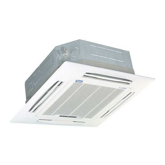
Features External Appearance 2.1 Indoor Units Four-way Ceiling Cassette Ceiling-floor Mount: Convertible 2.2 Outdoor Units KV24ODU-ARF21 KV48ODU-ARF21 KV36ODU-ARF21 General Information... -
Page 6: Nomenclature
Nomenclature Nomenclature 3.1 Indoor Unit F Console Type 3.2 Outdoor Unit Indoor Units... -
Page 7: Part
Features Features 4.1 Universal outdoor unit design Indoor unit with the same capacity can match with the same outdoor unit. 4.2 High efficiency and energy saving. Thanks to the DC inverter technology and optimized piping system, the EER and COP of whole series can easily reach A-class. -
Page 8: Indoor Units
Indoor Units Part 2 Indoor Units Four-way Ceiling Cassette Type ............7 Ceiling & Floor Type ................. 20 Indoor Units... -
Page 9: Table Of Contents
Four-way Ceiling Cassette Type Four-way Ceiling Cassette Type 1.Features ................... 8 2.Dimensions ..................11 3.Service Space ................12 4.Wiring Diagrams ................13 5.Capacity Tables ................14 6.Air Velocity and Temperature Distributions ........ 15 7.Electric Characteristics ..............16 8.Sound Levels ................. 16 9.Accessories .................. -
Page 10: Features
Features 1. Features (1) Low operation noise —Streamline plate ensures quietness —Creates natural and comfortable environment (3) Excellent performance. The optimal evaporator & sufficient airflow volume guarantees the excellent capacity (4) The adoption of the most advanced 3- Dimensional Screw fan —Reduces the air resistance passing through —Smoothes the air flow —Makes air speed distribution to the heat exchange uniform... - Page 11 Features (10) (11) (12) 4 speeds available, optional super high fan speed design suitable for the large building over 3m high. (13) Adding digital tube displaying on the display board. LED can display the Error Code to make the malfunction checking easier. Four-way Ceiling Cassette Type...
- Page 12 The Specification of Power (14) Reserve spaces for air side-outlet, it is available to connect duct pipe hence air supplying from the four sides to nearby small room.. ① (15) The connecting pipe and drop height is higher. Max. pipe length up to 50m ( refer to ), and Max.
-
Page 13: Dimensions
Field Wiring 2. Dimensions Unit: mm MODEL Ф15.9 Ф9.5 KV24CC-ARF21 >260 KV36CC-ARF21 Ф15.9 Ф9.5 >330 KV48CC-ARF21 Four-way Ceiling Cassette Type... -
Page 14: Service Space
The Specification of Power 3. Service Space N ece ssary room Drain side Tubing side outlet intlet outlet Chart 1 ground Note: 18000-24000Btu/h(R22) Series A 260m m ≥ 36000-48000Btu/h(R 22) Series A 330m m ≥ Ho ok B od y 780(Hook-location) 840(Body) 880(Ceiling hole) -
Page 15: Wiring Diagrams
Field Wiring 4. Wiring Diagrams KV24CC-ARF21, KV36CC-ARF21 KV48CC-ARF21 Four-way Ceiling Cassette Type... -
Page 16: Capacity Tables
The Specification of Power 5. Capacity Tables 5.1 Cooling Capacity KV24CC-ARF21 Cooling Outdoor conditions (DB) Indoor Conditions (kW) 21ºC 28ºC 35ºC 43ºC 7.52 7.15 6.79 6.50 21/15ºC DB/WB 5.56 5.51 5.43 5.46 Input 2.10 2.28 2.38 2.46 7.74 7.37 7.01 6.57 24/17ºC DB/WB 5.80... -
Page 17: Air Velocity And Temperature Distributions
Field Wiring 6. Air Velocity and Temperature Distributions Airflow velocity Temperature Four-way Ceiling Cassette Type... -
Page 18: Electric Characteristics
The Specification of Power 7. Electric Characteristics Indoor Unit Power Supply Model Voltage KV24CC-ARF21 220-240 KV36CC-ARF21 220-240 KV48CC-ARF21 220-240 Notes: MFA: Max. Fuse Amps. (A) 8. Sound Levels FOUR-W AY CASSE TTE TYPE 1.0m Microphone Noise level dB(A) Model KV24CC-ARF21 40.5 KV36CC-ARF21 42.5... -
Page 19: Accessories
Field Wiring 9. Accessories Name Shape Quantity INSTALLATION FITTINGS Installation paper board Soundproof / insulation sheath Tubing & Fittings Connecting pipe group Out-let pipe sheath Out-let pipe clasp Drainpipe Fittings Drain joint Seal ring Remote controller & Its Frame Remote controller & Its Remote controller holder Frame Mounting screw(ST2.9×10-C-H) -
Page 20: The Specification Of Power
The Specification of Power 10. The Specification of Power KV36CC-ARF21 Type KV24CC-ARF21 KV48CC-ARF21 Phase 1- Phase 1- Phase 220-240V~, 220-240V~, Frequency and Voltage 60Hz 60Hz Indoor unit Power Power Wiring(mm 3X1.0 3X1.0 Circuit Breaker(A) Phase 1- Phase 1- Phase Frequency and Voltage 220-240V~,60Hz 220-240V~,60Hz Outdoor unit Power... -
Page 21: Field Wiring
Field Wiring 11. Field Wiring Wiring chart KV24CC-ARF21, KV36CC-ARF21, KV48CC-ARF21 Four-way Ceiling Cassette Type... - Page 22 Ceiling & Floor Type Ceiling & Floor Type 1.Features ..................21 2.Dimensions ................... 22 3.Service Space ................23 4.Wiring Diagrams ................23 5.Capacity Tables ................24 6.Air Velocity and Temperature Distributions ........ 26 7.Electric Characteristics ..............28 8.Sound Levels ................28 9.Accessories ..................
-
Page 23: Features
Field Wiring 1. Features 1.1. New design, more modern and elegant appearance. 1.2. Convenient installation --The ceiling type can be easily installed into a corner of the ceiling even if the ceiling is very narrow --It is especially useful when installation of an air conditioner in the center of the ceiling is impossible due to a structure such as one lighting. -
Page 24: Dimensions
The Specification of Power 2. Dimensions a. Wall mounting installation b. Ceiling installation Capacity (Btu/h) KV24CM-ARF21 KV36CM-ARF21 1280 1195 KV48CM-ARF21 1670 1070 1542 Ceiling & Floor Type... -
Page 25: Service Space
Field Wiring 3. Service Space Ceiling & Floor Type... -
Page 26: Wiring Diagrams
The Specification of Power 4. Wiring Diagrams KV24CM-ARF21, KV36CM-ARF21 KV48CM-ARF21 Ceiling & Floor Type... -
Page 27: Capacity Tables
Field Wiring 5. Capacity Tables 6.1 Cooling Capacity KV24CM-ARF21 Cooling Outdoor conditions (DB) Indoor Conditions (kW) 21ºC 28ºC 35ºC 43ºC 7.52 7.15 6.79 6.50 21/15ºC DB/WB 5.56 5.51 5.43 5.46 Input 2.10 2.28 2.38 2.46 7.74 7.37 7.01 6.57 24/17ºC DB/WB 5.80 5.75 5.68... -
Page 28: Air Velocity And Temperature Distributions
The Specification of Power 6. Air Velocity and Temperature Distributions Discharge angle 60° (CEILING) Airflow velocity Temperature Ceiling & Floor Type... - Page 29 Field Wiring Discharge angle 60° (FLOOR) Airflow velocity Temperature Ceiling & Floor Type...
-
Page 30: Electric Characteristics
The Specification of Power 7. Electric Characteristics Indoor Unit Power Supply Model Voltage KV24CM-ARF21 220-240 KV36CM-ARF21 220-240 KV48CM-ARF21 220-240 Notes: MFA: Max. Fuse Amps. (A) 8. Sound Levels Ceiling Floor Noise level dB(A) Model KV24CM-ARF21 KV36CM-ARF21 KV48CM-ARF21 Ceiling & Floor Type... -
Page 31: Accessories
Field Wiring 9. Accessories Name Shape Quantity 1.Hook Installation fittings 2.Hanging arm 3. Remote controller Remote controller & Its 4. Remote controller holder holder 5. Mounting screw (ST2.9×10-C-H) 6. Alkaline dry batteries (AM4) 7. Owner's manual Others 8. Installation manual 9. -
Page 32: The Specification Of Power
The Specification of Power 10. The Specification of Power KV24CM-ARF21 Type KV36CM-ARF21 KV48CM-ARF21 Phase 1- Phase Frequency and Voltage 220V~,60Hz Indoor unit Power Power Wiring(mm 3X1.0 Circuit Breaker(A) Phase 1- Phase Frequency and Voltage 220V~,60Hz Outdoor unit Power Power Wiring(mm 3X3.3 Circuit Breaker(A) Indoor/outdoor connection wiring(Weak Electric Signal) (mm... -
Page 33: Field Wiring
Field Wiring 11. Field Wiring Wiring chart Ceiling & Floor Type... -
Page 34: Outdoor Units
Outdoor Unit Part 3 Outdoor Units 1.Dimensions ..................33 2.Service Space ................35 4.Wiring Diagrams ................37 5.Electric Characteristics ..............40 6.Operation Limits ................41 7.Sound Levels ................. 42 8.Troubleshooting ................43 Outdoor Unit... -
Page 35: Dimensions
Operation Limits Dimensions Unit: mm MODEL KV24ODU-ARF21 KV36ODU-ARF21 Outdoor Units... - Page 36 Electric Characteristics Unit: mm MODEL KV48ODU-ARF21 1245 Outdoor Units...
-
Page 37: Service Space
Operation Limits Service Space (Wall or obstacle) Air inlet More than 30cm More than 60cm More than 30cm Maintain channel Air inlet More than 60cm Air outlet More than 200cm Outdoor Units... -
Page 38: Piping Diagrams
T4 Ambient (CONDENSER) sensor temp. sensor T2 Evaporator temp. sensor T5 Discharge Accumulator temp. sensor GAS SIDE COMPRESSOR Notes: KV24ODU-ARF21(220075301740) & KV36ODU-ARF21(220075502120) have no EXV. KV48ODU-ARF21 INDOOR OUTDOOR Electronic CAPILIARY TUBE expansion valve LIQUID SIDE T3 Condenser temp. sensor HEAT... -
Page 39: Wiring Diagrams
Operation Limits Wiring Diagrams KV24ODU-ARF21(220075301510) KV24ODU-ARF21(220075301740) Outdoor Units... - Page 40 Electric Characteristics KV36ODU-ARF21(220075501730) KV36ODU-ARF21(220075502120) Outdoor Units...
- Page 41 Operation Limits KV48ODU-ARF21 Outdoor Units...
-
Page 42: Electric Characteristics
Electric Characteristics Electric Characteristics Outdoor Unit Model Voltage Min. Max. KV24ODU-ARF21 220-240 KV36ODU-ARF21 220-240 KV48ODU-ARF21 220-240 Outdoor Units... -
Page 43: Operation Limits
Operation Limits Operation Limits Temperature Cooling operation Mode ≥17 Room temperature ℃ 0℃~50℃ -15 ~ 50 :For ℃ ℃ Outdoor temperature ( the models with low temperature cooling system) CAUTION: 1. If the air conditioner is used beyond the above conditions, certain safety protection features may come into operation and cause the unit to operate abnormally. -
Page 44: Sound Levels
Electric Characteristics Sound Levels Outdoor Unit Microphone 1.0m Note: H= 0.5 × height of outdoor unit Model Noise level dB(A) KV24ODU-ARF21 KV36ODU-ARF21 KV48ODU-ARF21 Outdoor Units... -
Page 45: Troubleshooting
Operation Limits 8. Troubleshooting 9.1 Indoor unit malfunction 9.1.1 Display board Normal 4-way cassette Ceiling & Floor Outdoor Units... - Page 46 Electric Characteristics 9.1.2 Troubleshooting Running Timer Defrosting Alarm Display(nixie Malfunction lamp lamp lamp lamp tube) Communication malfunction between indoor ☆ and outdoor units. Open or short circuit of T1 temperature ☆ sensor Open or short circuit of T2 temperature ☆ sensor Open or short circuit of T2B temperature ☆...
- Page 47 Operation Limits 2. Timer lamp flashes Timer lamp flashes at 5Hz Judge: Indoor/outdoor unit communication is abnormal Refer to the outdoor unit LED display E2 malfunction in the following part 3. Alarm lamp slow-flash Indoor alarm lamps flash at 1Hz Condenser temp.
- Page 48 Electric Characteristics 4. Alarm lamp quick-flash Alarm lamp flashes at 5Hz Judge: Water level switch is abnormal. Replace water pump Check whether the water pump can work normally Select the cooling mode to make water pump work for a few minutes, then Trouble is solved check whether the system can run normally Solve to make the water can flow...
- Page 49 Operation Limits 9.2 Outdoor unit malfunction Display Malfunction or Protection EEPROM malfunction Communication malfunction between indoor IC and outdoor IC Communication malfunction in outdoor IC and DSP Malfunction of outdoor temperature sensor Voltage protection of compressor PFC module protection (Only for 36K, 48K) Top temperature protection of compressor High pressure protection Low pressure protection...
- Page 50 Electric Characteristics 2. E2 malfunction E2 display Communication malfunction between indoor IC and outdoor Judge 1: Check whether the indoor unit power is on Turn on the indoor unit power Judge 2: Check whether the signal wiring is shield cable or whether Adopt the shield cable/ let shield cable earthed the shield cable is earthed Judge 3: Check whether the signal wiring between the indoor and...
- Page 51 Operation Limits 3. E3 malfunction (For 18K & 24K & 30K) E3 display Communication malfunction in outdoor IC and DSP Check whether the indicator lights LED1 on the main board is flashing Replace the outdoor main board Check whether the connecting wiring between the IPM module and the CN4 Insert the connecting wiring well over on the main board is broken off again...
- Page 52 Electric Characteristics 4. E3 malfunction (For 36K & 48K & 60K) E3 display Communication malfunction in outdoor IC and DSP Check whether the indicator lights LED1 or LED2 on the main control board are flashing Replace PCB Install the IC-U3 chip of the PCB over again, check whether the Trouble is solved system can run normally Check whether the output of the transformer to CN4 socket is well...
- Page 53 Operation Limits 5. E4 malfunction E4 display Judge 1: Outdoor condenser temp. sensor (T3) is malfunction Connect the wiring well Check whether the wiring of the condenser temp. sensor is broken off Check whether the resistance of condenser temp. sensor is wrong refer to the Annex 1 Replace condenser temp.
- Page 54 Electric Characteristics 6. E5 malfunction E5 display Voltage protection of compressor Check the voltage of outdoor unit power supply, whether the voltage Check the power supply between L(1) and N is about 172-265V Replace the power board, then check whether the system can run normally Trouble is solved Replace outdoor main board 7.
- Page 55 Operation Limits 8. P0 malfunction P0 display Top temperature protection of compressor Judge 1: Whether compressor operates? Whether Reconnect and connection is good? retest. Judge 2: Whether refrigerant circulation volume is Whether protector is Replace the protector. normal? normal? Method: Charge refrigerant Check the outdoor Replace the protector.
- Page 56 Electric Characteristics 9. P1 malfunction P1 display High pressure protection Judge 1: Whether the wiring between the high pressure switch and main Connect it well control board is connected well or correctly Judge 2: Whether the high pressure switch is broken Method: Short connect the high pressure switch socket, check Replace high pressure switch whether the system can run normally...
- Page 57 Operation Limits 10. P2 malfunction P2 display Low pressure protection Judge 1: The wiring between the low pressure switch and main control board is connected well or correctly Connect it well Judge 2: Whether the low pressure switch is broken Method: Short connect the low pressure switch socket, check Replace low pressure switch whether the system can run normally...
- Page 58 Electric Characteristics 11. P3 malfunction P3 display Current protection of compressor Judge 1: Check whether the input current of the power supply wire is more than 20A (For 36K & 48K with 1 phase, it is 30A) Check whether the refrigerant system is ok Judge 2: Check whether the outdoor ambient temperature is too high Stop the unit Make the outdoor unit ventilate well...
- Page 61 Operation Limits 14. P6 malfunction (For single phase units) P6 display Module protection Check whether the voltage range of P-N on IPM module is normal? DC277-356V for Regulate it to correct, 18K/24K/30KBtu/h; DC277-410V for then check whether the 36K/48KBtu/h Check whether the input power supply system can work is correct? 220-240V, 1N, 60Hz normally?
- Page 62 Electric Characteristics 15. P6 malfunction (For three phases units) P6 display Module protection Regulate it to correct, then check whether the Check whether the voltage range of P-N on Check whether the input power supply system can work IPM module is normal? DC 350-650V is correct? 380-415V, 3N, 60Hz normally? Check whether the connecting line...
- Page 63 Operation Limits P7 display High temperature protection of evaporator Whether compressor operates? Whether Reconnect and connection is good? retest. Check whether the heat exchanger is dirty, the air- Whether Replace the outlet is blocked and the indoor fan is normal? temperature sensor temperature sensor is normal?
- Page 64 Electric Characteristics Appendix Indoor Temp. and Pipe Temp. Sensor Resistance Value Table ( --K) ℃ K Ohm K Ohm K Ohm K Ohm ℃ ℃ ℃ ℃ ℃ ℃ ℃ ℃ ℃ ℃ ℃ ℃ ℃ ℃ ℃ ℃ 115.266 12.6431 2.35774 0.62973...
-
Page 65: Installation
Installation Part 4 Installation 1.Precaution on Installation ............. 64 2.Vacuum Dry and Leakage Checking ..........65 3.Additional Refrigerant Charge ............ 67 4.Water Drainage ................68 5.Insulation Work ................71 6.Wiring ..................... 72 7.Test Operation ................73 Installation... -
Page 67: Vacuum Dry And Leakage Checking
Test Operation 2. Vacuum Dry and Leakage Checking Vacuum Dry: use vacuum pump to change the moisture (liquid) into steam (gas) in the pipe and discharge it out of the pipe to make the pipe dry. Under one atmospheric pressure, the boiling point of water(steam temperature) is 100 . Use vacuum pump to make the ℃... - Page 68 Water Drainage ②. Special vacuum dry procedure This vacuum dry method is used in the following conditions: There’s moisture when flushing the refrigerant pipe. Rainwater may enter into the pipe. Vacuum dry for the first time ······ 2h pumping ③. Vacuum destroy for the second time ······ Fill nitrogen to 0.5Kgf/cm Because nitrogen is for drying gas, it has vacuum drying effect during vacuum destroy.
-
Page 69: Additional Refrigerant Charge
Test Operation Additional Refrigerant Charge Caution: Refrigerant cannot be charged until field wiring has been completed. Refrigerant may only be charged after performing the leak test and the vacuum pumping. When charging a system, care shall be taken that its maximum permissible charge is never exceeded, in view of the danger of liquid hammer. -
Page 70: Water Drainage
Water Drainage Water Drainage 4.1 Gradient and Supporting 1). Keep the drainpipe sloping downwards at a gradient of at least 1/50. Keep the drainpipe as short as possible and eliminate the air bubble. 2). The horizontal drainpipe should be short. When the pipe is too long, a prop stand must be installed to keep the gradient of 1/50 and prevent bending. -
Page 71: Drainage Test
Test Operation For Four-way cassette 4.4 Convergent drainage 1). The number of indoor units should be as small as possible to prevent the traverse main pipe overlong. 2). Indoor unit with drain pump and indoor unit without drain pump should be in different drainage system. 3). - Page 72 Water Drainage ③ Stop the air conditioner running, turn off the power, and put back the cover. Stop the air conditioner. After 3 minutes, check if it has abnormity. If the collocation of drainpipes is illogical, the water will flow back overfull, which will cause the alarm lamp flashes, even overflow from the water receipt plate. Keep on pouring water until it gives an alarm signal for high water level, check if the pump drains water at once.
-
Page 73: Insulation Work
Test Operation Insulation Work 5.1 Insulation material and thickness 1). Insulation material Insulation material should adopt the material which is able to endure the pipe’s temperature: no less than 70 in the high-pressure side, no ℃ less than 120 in the low-pressure side(For the cooling type machine, no requirements at the low-pressure side.) ℃... -
Page 74: Wiring
Wiring For construction convenience, before laying pipes, use insulation material to insulate the pipes to be deal with, at the same time, at two ends of the pipe, remain some length not to be insulated, in order to be welded and check the leakage after laying the pipes. 3). -
Page 75: Test Operation
Test Operation Test Operation (1) The test operation must be carried out after the entire installation has been completed. (2) Please confirm the following points before the test operation. The indoor unit and outdoor unit are installed properly. Tubing and wiring are correctly completed. The refrigerant pipe system is leakage-checked. -
Page 76: Control
Control Part 5 Control 1.Wireless Remote Controller ............75 Control... -
Page 77: Wireless Remote Controller
1. Wireless Remote Controller 1.1 RG51Q1/BG(C)E S E T TE M P E RA TURE ( C) A UT O F A N CO O L HIG H M E D HE A T LO W A DJUS T A djust A djust O N/O FF O N/O F F... - Page 78 Buttons and functions 1. Adjust : Decrease the set temp. Keeping pressing will decrease the temp with 1℃ per 0.5s. ℃ per 0.5s. 3. MODE: Once pressing, running mode will be selected in the following sequence: AUTO COOL HEAT NOTE: No heating mode for cool only type unit. 4.
Need help?
Do you have a question about the KV24ODU-ARF21 and is the answer not in the manual?
Questions and answers