
Subscribe to Our Youtube Channel
Related Manuals for koppel KWR-12M4A2


Summary of Contents for koppel KWR-12M4A2
- Page 1 Before using your air conditioner, please read this manual carefully and keep it for future reference. WINDOW TYPE ROOM AIR CONDITIONER Owner’s Manual & Installation Manual...
-
Page 2: Table Of Contents
Table of Contents Safety Precautions .................03 Unit Parts Identification ................13 Care and Maintenance ................17 Water Drainage ..................18 Installation Instructions ..............19 Troubleshooting ..................23 Specifications ....................25 European Disposal Guidelines This marking shown on the product or its literature, indicates that waste electrical and eletrical equipment should not be mixed with general household waste. -
Page 3: Safety Precautions
Safety Precautions Read Safety Precautions Before Operation and Installation Incorrect installation due to ignoring instructions can cause serious damage or injury. The seriousness of potential damage or injuries is classified as either a WARNING or CAUTION. CAUTION WARNING This symbol indicates the possibility of This symbol indicates the possibility property damage or serious consequences. - Page 4 CLEANING AND MAINTENANCE WARNINGS Turn off the device and disconnect the power before cleaning. Failure to do so can cause • electrical shock. Do not clean the air conditioner with excessive amounts of water. • Do not clean the air conditioner with combustible cleaning agents. Combustible cleaning agents •...
- Page 5 Wall outlet Air-break switch TAKE NOTE OF FUSE SPECIFICATIONS The air conditioner’s circuit board (PCB) is designed with a fuse to provide overcurrent protection. The specifications of the fuse are printed on the circuit board ,such as T3.15A/250V(or 350V), etc, WARNINGS FOR PRODUCT INSTALLATION 1.
- Page 6 WARNING for Using R32/R290 Refrigerant -Do not use means to accelerate the defrosting process or to clean, other than those recommended by the manufacturer. -The appliance shall be stored in a room without continuously operating ignition sources (for example: open flames, an operating gas appliance) and ignition sourcesor (for example:an operating electric heater) close to the appliance.
- Page 7 Explanation of symbols displayed on the unit(For the unit adopts R32/R290 Refrigerant only): This symbol shows that this appliance used a flammable refrigerant. If the refrigerant is leaked and exposed to an external ignition source, there is a risk of fire. WARNING This symbol shows that the operation manual should be read carefully.
- Page 8 appropriate fire extinguishing equipment shall be available to hand. Have a dry powder or CO2 fire extinguisher adjacent to the charging area. 6)No ignition sources No person carrying out work in relation to a refrigeration system which involves exposing any pipe work that contains or has contained flammable refrigerant shall use any sources of ignition in such a manner that it may lead to the risk of fire or explosion.
- Page 9 equipment being worked upon prior to any removal of sealed covers, etc. If it isabsolutely necessary to have an electrical supply to equipment during servicing, then a permanently operating form of leak detection shall be located at the most critical point to warn of a potentially hazardous situation.
- Page 10 12.Removal and evacuation When breaking into the refrigerant circuit to make repairs or for any other purpose conventional procedures shall be used. However, it is important that best practice is followed since flammability is a consideration. Opening of the refrigeration systems shall not be done by brazing.
- Page 11 e)If a vacuum is not possible, make a manifold so that refrigerant can be removed from various parts of the system. f)Make sure that cylinder is situated on the scales before recovery takes place. g)Start the recovery machine and operate in accordance with manufacturer's instructions. h)Do not overfill cylinders.
- Page 12 When flammable refrigerant are employed, appliance shall be stored in a well -ventilated area where the room size corresponds to the room area as specific for operation. For factory sealed appliances, the nameplate on the unit itself marked the refrigerant charge can be used to calculate .
-
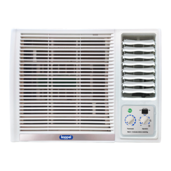
Page 13: Unit Parts Identification
UNIT PARTS IDENTIFICATION NOTE: Different models have different front panels and cabinets. Illustrations in this manual are for explanatory purposes. The actual shape of your indoor unit may be slightly different. The actual shape shall prevail. See the following figures for references: 1. - Page 16 Operation panel cover (some units) For the units with operation panel cover (see the left figures of A & B) 1. Grasp the top or the left of the operation cover and pull it to open it. 2. Close the operation cover and press the cover again until it snaps into the locked position.
-
Page 17: Care And Maintenance
CARE AND MAINTENANCE Cleaning Your Unit If your filter has a small air freshening filter, clean this air freshening filter with a hand-held BEFORE CLEANING OR vacuum. MAINTENANCE Rinse the air filter with fresh water, then shake ALWAYS TURN OFF YOUR AIR CONDITIONER off excess water. -
Page 18: Water Drainage
WATER DRAINAGE The condensed water can be treated as follows: Bottom drainage (Applicable for the units designed with bottom drain hole only. ) - Remove the rubber plug from the bottom of cabinet(if any) - Take out the drain pan and screws from accessary. Bottom drain - Fix the drain pan onto the bottom of cabinet by screws. -
Page 19: Installation Instructions
INSTALLATION INSTRUCTIONS Prior to installation CAUTION: Before installing, remove all packaging from inside the carton, along with any inserts placed into the side louvers. Remove inserts placed Step 1: Select the best location into the side louvers 1. To avoid vibration and noise, make sure the unit is installed securely and firmly. - Page 20 Step 3: Remove the frame NOTE: There are slight differences on removing the frame according to the different models. Model A: 1. Remove one screw securing the chassis fixing bracket, then take down the chassis fixing bracket as shown in Fig.3A. 2.
- Page 21 Step 4: Install the cabinet Flash or seal around external wall frame or architrave NOTE: Unit may be supported by a solid frame from below or by a hanger from a solid overhead support(not suppied, purchase separately, please contact the dealer). Drain pan 1.
- Page 22 Step 7: Install the air filter and front panel 1. Insert the air filter into the frame’s slot from upside to underside.(See Fig. 2) 2. Hang the front panel on the frame’s buckle, then press the front panel into the frame’s slot until Fig.10 you hear a click (see Fig.10).
-
Page 23: Troubleshooting
Troubleshooting SAFETY PRECAUTIONS If ANY of the following conditions occurs, turn off your unit immediately! The power cord is damaged or abnormally warm • You smell a burning odor • The unit emits loud or abnormal sounds • A power fuse blows or the circuit breaker frequently trips •... - Page 24 Issue Possible Causes Dirty air filter- air restricted. Clean air filter. Refer to Care and Maintenance section. Air conditioner cooling, Thermostat set too warm. Turn thermostat clockwise to a colder setting. but room is too warm- All directional louvers positioned improperly. Position louvers for better air NO ice forming on distribution.
-
Page 25: Specifications
BODY DIMENSION(WxHxD) (But/h) (mm) 450x346x585 KWR-12M4A2 Note: For the different customization requirements, the depth of the panel may be slightly different. So the dimension of “D” is for reference only. Choose the right cable size The size of the power supply cable, signal cable, fuse, and switch needed is determined by the maximum current of the unit. - Page 28 Rizal Street, Lapuz, Iloilo City Tel No.: (033) 330-2926 Cebu Office: Door 1 & 2 Rozen Bldg., A. Cortez Avenue, Mandaue City Koppel Head Office: Tel No.: (032) 346-7278 106 Industry Drive, Carmelray Fax No.: (032) 346-7279 Industrial Park 1, Brgy. Canlubang,...
Need help?
Do you have a question about the KWR-12M4A2 and is the answer not in the manual?
Questions and answers