Table of Contents
Advertisement
Quick Links
Advertisement
Table of Contents

Subscribe to Our Youtube Channel
Related Manuals for Trannergy PVI 1800


Summary of Contents for Trannergy PVI 1800
- Page 1 User Manual PVI 1800 / 2300 / 3200 / 4000 / 4600 / 5400TL...
-
Page 3: Table Of Contents
Contents Copyright Declaration ....................... 3 1. Introduction ........................... 4 1.1. Introduction ........................4 1.2. How to Use this manual ....................4 1.3. Applied Designations (Warning, Caution, Note) ............4 1.4. Important Safety Information ..................4 1.5. General Safety Rules for Working on Electrical Equipment.......... 5 1.6. - Page 4 6. Communication and Monitoring ..................32 6.1. Communication Interfaces.................... 32 6.2. Communication ......................32 6.2.1. RS-232 Communication for single inverter type........... 32 6.2.2. RS-485 Communication for Several inverters............33 6.2.3. Wireless ......................... 34 6.3. Monitoring........................34 7. Service and repair ........................ 35 7.1.
-
Page 5: Copyright Declaration
Copyright Declaration The copyright of this manual belongs to Shanghai Trannergy Power Electronics Co., Ltd. Any corporation or individual should not plagiarize, partially copy or fully copy it (including software, etc.), and no reproduction or distribution of it in any form or by any means. -
Page 6: Introduction
1. Introduction 1.1. Introduction This manual describes Trannergy solar inverters PVI1800TL , PVI2300TL, PVI3200TL, PVI4000TL, PVI4600TL and PVI5400TL. These products are among the most technologically advanced and efficient inverters on the market and are designed to ensure a stable power supply for many years. -
Page 7: General Safety Rules For Working On Electrical Equipment
Additionally it will lead to the cancelling of all inverter operating approval certificates. The Trannergy inverters in the PVI range are all designed according to the German VDE0126-1-1standard. If non-original spare parts are used, the compliance with CE guidelines in respect of electrical safety, EMC and machine safety is not guaranteed. -
Page 8: System Sizing
have experience with the general safety rules to be observed when working on electrical equipment. Installation and service personnel should also be familiar with local requirements, rules and regulations as well as safety requirements. To provide a general guideline for safety precautions, five well-known and widely accepted rules are repeated below. -
Page 9: Dc-Switch
The limitation is calculated continuously and always allows the maximum possible amount of energy to be produced. Please use the tool supplied by Trannergy when dimensioning a photovoltaic system. 1.7. DC-switch On1y trained and authorized personnel familiar with local electrical codes may perform service or maintenance on the inverter. -
Page 10: Technical Description Of Inverters
2. Technical Description of Inverters 2.1. Mechanical design Figure 2-1 shows the outline dimensions of PVI1800TL&PVI2300TL: Figure 2-1 Outline dimensions of PVI1800TL&PVI2300TL Figure 2-2 shows the outline dimensions of PVI3200TL, PVI4000TL, PVI4600TL and PVI5400TL: Figure 2-2 Outline dimensions of PVI3200/4000/4600/5400TL User Manual... -
Page 11: Electrical System Design
DC EMI/EMC Filter AC EMI/EMC Filter & GFCI EMCA AC Circuit Breaker DC Circuit Breaker PV1+ PV1- PV2- PV2+ 125-550Vdc 30Vac Solar Array Shanghai Trannergy Power Electronics Co.,Ltd. Grid Figure 2-3 wiring diagram of the whole PVI1800/2300/3200/4000/4600/5400TL system User Manual... - Page 12 We recommend a 32A DC Breaker located at the input of the DC input, and a 32A AC Breaker located at the output of the AC part. Notes: When choose the breaker, please call your installer for technique support For the input and output wire selection, we recommend UL1015 wire, please see the following table.
-
Page 13: Operation Mode Definition
3. Operation Mode Definition The inverter has four standard operation modes. 3.1. Waiting mode In waiting mode, the inverter is ready to switch into connecting mode. As decision variable the input voltage of the PV generator is used. Inverter is waiting to checking when output DC voltage from PV panels is greater than 100V (lowest start-up voltage) but less than 150V (lowest operating voltage). - Page 14 LCD display Possible actions Isolation Fault 1. Check the impedance between PV (+)&PV(-) and the inverter is earthed. The impedance must be greater than 2MΩ 2. Check whether the AC end has contacted with earth Ground Fault 1. The ground current is too high 2.
-
Page 15: Installation And Startup
The Trannergy inverter may become hot in normal operation. Do not install the Trannergy inverter on easily flammable materials and where flammable materials are stored. Do not install the Trannergy inverter where there is a risk of explosion. Caution! Danger of burns from hot housing components! Install the Trannergy inverter at a proper place where it cannot be touched unintentional. - Page 16 Figure 4-2 Dimensions for PVI3200TL/ PVI4000TL/PVI4600TL/PVI5400TL: Figure 4-3 User Manual...
- Page 17 Ambient conditions The area where the Trannergy inverter installed is as dry as possible in order to extend their service life. Ensure good access to the unit for installation or any service work that may later be required. Ensure that equipment out of the children's reach.
-
Page 18: Installing The Inverter
15° install ation. Do no ot install the Trannergy inverter for rwards. Never r install it ho orizontally. Install l at eye leve el makes it e easier to ope... - Page 19 200 ±3 mm Figure 4-6 b) Install the Installation board After drilling holes in the wall, fix the installation board (object 2) on the wall with the expansion bolts (object 1). Figure 4-7 User Manual...
-
Page 20: Pvi3200/4000/4600/5400Tl
Attention! Before inserting expansion bolts, measure the depth of every hole and measure the distance between every two holes. If the measures values do not meet installing requirements, re-drill holes in the wall. c) Hung the inverter on the installation board. Figure 4-8 d) Check both sides for correct positioning. - Page 21 200±3mm 6- 10 Figure 4-9 User Manual...
- Page 22 b) Install the Installation board After drilling holes in the wall, fix the installation board (object 2) on the wall with the expansion bolts (object 1). Figure 4-10 Attention! Before inserting expansion tubes, measure the depth of every hole the distance between every two holes. If the measures values do not meet installing requirements, re-drill holes in the wall.
-
Page 23: Electrical Connection
Figure 4-11 d) Check both sides for correct positioning. 4.3. Electrical connection User Manual... - Page 24 Figure 4-12 Object Description Plug connectors for DC input. Their polarity is signed lost to the Corresponding connectors Communication terminal:RS485 or RS232 interface Terminal for grid connection (AC output) DC Switch Note! 1) After the inverter has been installed in its fixed position, the electrical connection to the unit can be established.
- Page 25 5) Sources and secured against being inadvertently switched back on. 6) Before connecting inverter to PV modules and public grid, please make sure the Polarity is correct. Connection to the grid (AC) Attention! You must safeguard each inverter with an individual AC breaker in order that the inverter can be safely disconnected under load.
- Page 26 Open the connector: Figure 4-15 Connect the wires: Wire L Hole L Wire N Hole N Hole Wire PE Figure 4-16 After fasten the three wires, combine every component together. Close the connector: Figure 4-17 Finally, connect the AC female connector to the AC male connector on the inverter.
- Page 27 Figure 4-18 Connection to the PV generator (DC) Attention! In order to safeguard the installation and startup of the device, a manual DC breaker must be fit at the input end of the inverter. The breaker should have certain capacity of over current and over voltage.
- Page 28 Connect the PV generator and the inverter using H4 connectors as below. The positive and negative terminals of the PV generator are corresponding to positive (+) terminals and negative (-) terminals on the inverter. Figure4-19 Female side connector (+) Figure4-20 Male side connector (-) Switch off the DC breaker and secure against being switched back on inadvertently.
-
Page 29: Run The Inverter
Figure 4-25 Male side connector DANGER! DANGER to life due to potential fire or electricity shock. NEVER connect or disconnect the connectors under load. 4.4. Run the inverter Start inverter after checking all below steps a) Make sure all the DC breaker and AC breaker are disconnected. b) AC cable is connected to grid correctly. -
Page 30: Human Machine Interface
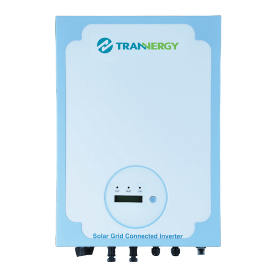
5. Human Machine Interface 5.1. Control Panel Figure 5-1 A—Green LED: Working Normally B—Red LED: Fault detected. C—Yellow LED: Communication or updating firmware D—Function key: For settings. It can alternate among different parameters and different languages. User Manual... -
Page 31: Lcd Functions
5.2. LCD Functions 5.3. Language Settings Language setting function is as below: User Manual... - Page 32 5.4. Auto Test Settings For the customers in Italy, who need to perform the auto test function, please set according to the following instructions. Please make sure the PV inverter is made for Italian Standard. (You will see machine type and ENEL if you press the switch for several time when the PV is running.) During the auto test procedure, if anything abnormal happens, please wait until the inverter run normally, then make the auto test settings from the beginning.
- Page 33 V↑ V↑ V↓ V↑ f↓ f↑ f↓ f↑ User Manual...
-
Page 34: Communication And Monitoring
6. Communication and Monitoring 6.1. Communication Interfaces This product has a communication interface RS-232, RS-485 and Wireless (optional). Operating information like output voltage, current, frequency, fault information, etc., can be delivered to PC or hardware storage devices or other monitoring equipment via communication interface. 6.2. -
Page 35: Rs-485 Communication For Several Inverters
Notes: If your computer doesn’t have the DB9 communication interface, you can use RS232-USB cable to achieve this function. One inverter can only be communicated with one PC at the same time through RS-232 port. Thus this method is generally used for single inverter’s communication, for examples, software updating and serviceman’s testing. -
Page 36: Wireless
6.2.3. Wireless PVI1800/2300/3200/4000/4600/5400TL can be communicated with wireless. Trannergy can customize the required special device from customers to realize wireless communication. 6.3. Monitoring System monitor PVCS should be configured to realize one PC communicates with multi inverters at the same time. Through PC PVCS could get real time PV plants operating data. -
Page 37: Service And Repair
7. Service and repair 7.1. Safety during service and repair In this chapter the term ‘event’ describes all conditions preventing the inverter from operating properly. An event can occur in any part of the system (grid, PV modules, cables and connectors, inverter), and does not automatically indicate an inverter failure. - Page 38 Use this check list first if you experience problems with your PV system: 1) Check the event at the LCD, An event is indicated at the LCD 2) Check that AC grid voltage is within the normal range(see LCD information) 3) If not, check whether the AC isolation switch is connected, and whether the AC grid is available.
-
Page 39: Technique Specification
8. Technique specification This specification is regarding to a series of Transformerless Photovoltaic Inverters (PV Inverter) developed by Trannergy for customers. The inverter is used to convert DC power from solar array to AC power fed to grid in distributed power applications. -
Page 40: General Data
Nominal output current 10.2 14.2 18.6 20.4 23.6 Maximum output current 11.3 15.7 20.4 22.5 i t r < > 8.1.3. General Data Model PVI1800TL PVI2300TL PVI3200TL PVI4000TL PVI4600TL PVI5400TL Internal power consumption <5W <6W <6W <6W <6W Standby power (at night) <0.2W <0.2W <0.2W... -
Page 41: Qualification
9. Qualification We grant a warranty of 60 months as standard, starting from the date of the purchase invoice marked. We will only perform warranty services when the faulty unit is returned to us together with a copy of the invoice and warranty card which are issued by the dealer to the user. -
Page 42: Contact Information
10. Contact Information If you have any further technical questions about our products, please contact us: Shanghai Trannergy Power Electronics Co., Ltd. www.trannergy.com Add: Floor 3, Floor 4, Building A3, No.699, Chuanhong Road, Pudong District, Shanghai, China, 201202 Tel: +86 21 38953908 Fax: +86 21 38953905 E-mail: info@trannergy.com... -
Page 43: Appendix A: Faq (Frequently Asked Questions)
Appendix A: FAQ (Frequently asked questions) Sometimes, the PV system does not work normally; we recommend the following solutions for average troubleshooting. This can help the technician to understand the problem and take a proper action. LCD display Possible actions Isolation Fault 1. -
Page 44: Appendix B: Abbreviation
Appendix B: Abbreviation Alternating Current Direct Current Data Logger Unit Digital Signal Processing EEPROM Electrically Erasable Programmable Read-Only Memory Electro Magnetic Compatibility Electro Magnetic Interference GFCI Ground Fault Circuit Interrupter Hall Current Transformer Human Machine Interface Liquid Crystal Display Light Emitting Diode MPPT Maximum Power Point Track Personal Computer... - Page 46 Shanghai Trannergy Power Electronics Co., Ltd. Add: Floor 3, Floor 4, Building A3, No.699, Chuanhong Road, Pudong District, Shanghai, China, 201202 Tel: +86 21 3895 3908 Fax: +86 21 3895 3905 E-mail: info@trannergy.com www.trannergy.com...
Need help?
Do you have a question about the PVI 1800 and is the answer not in the manual?
Questions and answers