Toshiba E-studio 352 Operator's Manual
Multifunctional digital systems
Hide thumbs
Also See for E-studio 352:
- Printing manual (386 pages) ,
- User functions manual (204 pages) ,
- Operator's manual (362 pages)
Table of Contents
Advertisement
Quick Links
Advertisement
Table of Contents

Related Manuals for Toshiba E-studio 352


Summary of Contents for Toshiba E-studio 352
- Page 1 MULTIFUNCTIONAL DIGITAL SYSTEMS Operator's Manual for Basic Function...
-
Page 3: Table Of Contents
CONTENTS Notice to Users ............................5 Toshiba Quality is Second to None ......................7 Preface ..............................10 Features ..............................11 General Precautions ..........................12 • When installing or moving ........................12 • When using the Multifunctional Digital Systems.................15 • During maintenance or inspection......................18 • When handling supplies ........................19 Disclaimer Notice...........................20... - Page 4 CONTENTS (Cont.) 2. Sharpness............................127 5. USING THE EDITING FUNCTIONS....................129 1. IMAGE SHIFT ..........................130 2. EDGE ERASE..........................136 3. BOOK CENTRE ERASE........................138 4. DUAL PAGE ..........................140 5. 2IN1 / 4IN1.............................142 6. MAGAZINE SORT .........................145 7. EDITING ............................147 • Trimming / Masking ........................147 •...
- Page 5 4. “READY (CHECK STAPLER)”.......................316 5. “Examine stapler in the Saddle Stitch Unit” ..................317 6. “READY (CHECK SADDLE STITCH STAPLER)” .................320 7. “READY (HOLE PUNCH DUST BIN IS FULL)” ................321 8. “POWER FAILURE”........................323 9. “Time for periodic maintenance” ....................324 10. “Check paper size setting on control panel for drawer N”..............325 11.
- Page 6 CONTENTS (Cont.)
-
Page 7: Notice To Users
CE marking is the responsibility of TOSHIBA TEC GERMANY IMAGING SYSTEMS GmbH, Carl- Schurz-Str. 7, 41460 Neuss, Germany, phone +49-(0)-2131-1245-0. For a copy of the related CE Declaration of Conformity, please contact your dealer or TOSHIBA TEC. For Germany only Machine Noise Information Ordinance 3. - Page 8 Notice to Users (Cont.) Following information is for EU-member states only: This product is marked according to the requirement in EU-Directive 2002/96/EC. (Directive on Waste electrical and electronic equipment - WEEE) The use of the symbol indicates that this product may not be disposed as unsorted municipal waste and has to be collected separately.
-
Page 9: Toshiba Quality Is Second To None
Toshiba Quality is Second to None It is recommended that genuine Toshiba supplies and parts be used to obtain optimum results. For e-STUDIO352/452... - Page 10 Toshiba Quality is Second to None (Cont.) For e-STUDIO353/453...
- Page 11 Genuine Toshiba supplies are designed to provide consistently stable image output. • Copier Friendly Supplies Genuine Toshiba supplies are designed to help to keep the copier and all its parts in trouble-free work- ing order. Reduction of machine wear is due to Toshiba’s intimate knowledge of the copier’s characteristics ensuring the highest standard of care.
-
Page 12: Preface
©2005 TOSHIBA TEC CORPORATION All rights reserved Under the copyright laws, this manual cannot be reproduced in any form without prior written permission of TOSHIBA TEC CORPORATION. No patent liability is assumed, however, with respect to the use of the information contained herein. -
Page 13: Features
Features The e-STUDIO352/452 or e-STUDIO353/453 is a Multifunctional Digital Systems that is capable of using each function via networks. The e-STUDIO352/452 or e-STUDIO353/453 also has various optional paper handling devices to meet the needs of your office. The e-STUDIO352/452 or e-STUDIO353/453 offers the following convenient features, functions and options. -
Page 14: General Precautions
General Precautions When installing or moving Warning • This Multifunctional Digital Systems requires 220 to 240 V AC, 8 A 50/60 Hz electric power. Do not use a power supply with a voltage other than that specified. Avoid multiple connections in the same outlet. This could cause a fire or give you an electric shock. If you are considering increasing the number of outlets, contact an electrician. - Page 15 Caution • Avoid placing the Multifunctional Digital Systems in a place unsuitable for its weight and also make sure the surface is level. Remember that if the Multifunctional Digital Systems falls over, serious injuries could result. Weight of the Multifunctional Digital Systems: approx. 83 kg. •...
- Page 16 General Precautions (Cont.) Other points • Make sure that there is enough space around the system to facilitate changing of parts, maintenance and clearing paper jam. If there is insufficient space, some operations, such as bypass feeding, will become difficult and the Multifunctional Digital Systems could even break down.
-
Page 17: When Using The Multifunctional Digital Systems
When using the Multifunctional Digital Systems Warning • Do not place metallic objects or containers with water (flower vases, coffee cups, etc.) on or near the Multifunctional Digital Systems. Keep paper clips and staples away from the air vent. If not, a fire could result or you could get an electric shock. - Page 18 General Precautions (Cont.) Position of Certification label, etc. Explanatory label Identification label Warning for earth wire Warning label Warning for high temperature area ( fuser unit ) Warning for high temperature area Warning for high temperature area ( ventilation holes )
- Page 19 Other points • Be very careful to treat the touch panel gently and never hit it. Breaking the surface could cause mal- functions. • Do not turn the power OFF with jammed paper left inside the Multifunctional Digital Systems. This could cause malfunctions when the main switch is turned ON next time. To turn the power OFF, see P.42 “Turning power off (Shutdown)”.
-
Page 20: During Maintenance Or Inspection
General Precautions (Cont.) During maintenance or inspection Warning • Never attempt to repair, disassemble or modify the Multifunctional Digital Systems by yourself. You could cause a fire or get an electric shock. Always contact your Service representative for maintenance or repair of the internal parts of the Multi- functional Digital Systems. -
Page 21: When Handling Supplies
When handling supplies Caution • Never attempt to incinerate toner cartridges and toner bags. This could cause an explosion. Do not dis- pose of used toner cartridges and toner bags. Contact your service representative. ( P.272 “3.Replace Toner Cartridge Symbol”, P.277 “4.Replace Toner Bag Symbol”) -
Page 22: Disclaimer Notice
2. All warranties, conditions and other terms implied by law are, to the fullest extent permitted by law, excluded and no such implied warranties are given or apply in relation to the Products. 3. TOSHIBA TEC CORPORATION shall not be liable for any loss, cost, expense, claim or damage what- soever caused by any of the following: (a) use or handling of the Product otherwise than in accordance with the manuals, including but not limited to Operator’s Manual, User’s Guide, and/or incorrect or careless handling or use of the Product;... -
Page 23: Environmental Information
ENERGY STAR Programme Toshiba Tec Corporation, as a member of the ENERGY STAR Programme, attaches the ENERGY STAR logo to all products which meet the ENERGY STAR Programme requirements. The ENERGY STAR Programme aims at the promotion of the development and wider usage of office equipment including energy-efficient computers in order to address environmental issues such as global warming. - Page 24 Environmental Information (Cont.)
-
Page 25: Energy Saving Mode
1. BEFORE USING EQUIPMENT 1. Description of Each Component ..................24 • Main components..........................24 • Configuration of options ........................25 • Control panel.............................28 • Adjustment of the angle of the control panel..................30 • Touch panel............................32 2. Turning Power On / Off ......................36 •... -
Page 26: Description Of Each Component
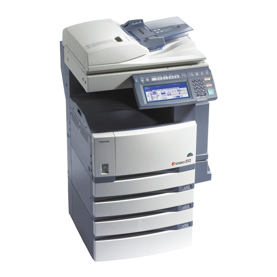
1. Description of Each Component Main components Front cover Receiving tray Drawers Control panel Operator’s Manual pocket (Back side) 10. Touch panel Power switch 11. Touch panel contrast adjustment dial Automatic duplexer 12. Toner cartridge Bypass tray 13. Toner bag Original scale A and B: Options ( 11 ) -
Page 27: Configuration Of Options
Configuration of options 1. Original Cover (KA-3511PC) Holds an original. 2. Reversing Automatic Document Feeder (MR-3018) Automatically feeds a placed stack of originals one by one to have them copied. 3. Offset Tray (MJ-5005) Enables copied and printed sets to be collated or stacked in groups with each set being offset. 4. - Page 28 This unit enables you to punch holes on printouts. It can be installed to the Finisher (Type B) (MJ-1101). Other options available are as follows. Contact your service technician or Toshiba product distributors for details. (Options may vary depending on destination.) Work Table (KK-3511) This is a small table for placing originals while the equipment is operated.
- Page 29 Scrambler Board (GP-1040) This board enhances the security of the equipment. Data are encrypted when they are written into the hard disk of the equipment, and decrypted when they are read. • Installed inside of the equipment • The PCI Slot (GO-1060) is necessary. Wireless LAN Module (GN-1041) This module enables the equipment to be used in a wireless LAN environment.
-
Page 30: Control Panel
1.Description of Each Component (Cont.) Control panel Use the buttons on the control panel for various operations and settings through the equipment. 1. [HELP] button Use this button to display the description of the functions and the buttons on the touch panel. 2. - Page 31 10. [INTERRUPT] button Use this button to interrupt the copy job in process and perform another one. The interrupted job is resumed by your pressing this button again. The equipment can be operated even while these lamps are lit. 11. [JOB STATUS] button Use this button to confirm the job status, printing status, and FAX transmission/reception status of a print job, scan job and FAX job.
-
Page 32: Adjustment Of The Angle Of The Control Panel
1.Description of Each Component (Cont.) Adjustment of the angle of the control panel When adjusting the angle of the control panel The angle of the control panel is adjustable at any angle between 7 and 45 degrees from the horizontal position. - Page 33 Fit the latches of the stopper in the hole of the position B and insert them turning the stopper itself. Shift the stopper to the left until it clicks. • The angle of the control panel is fixed at 7 degrees.
-
Page 34: Touch Panel
1.Description of Each Component (Cont.) Touch panel When the power is turned on, the basic menu for the copier function appears on this touch panel. The sta- tus of the equipment is also displayed on the touch panel with messages and illustrations. Message 10. - Page 35 [SETTINGS] button Press this button to confirm currently set functions. (An example is shown below.) Buttons appearing on the various menus are as follows (some buttons may not appear on the menu):...
-
Page 36: Adjusting The Contrast Of The Touch Panel
1.Description of Each Component (Cont.) Clearing functions selected When you press the selected button, the function which has been selected is cleared. Or the selected set- ting is cleared automatically by the automatic function clear* when the equipment has been left inactive for a specified period of time. -
Page 37: Setting Letters
Setting letters The following menu appears when any letter entry is required for the operations of scanning, e-Filing, tem- plate and Internet FAX. Use the buttons on the touch panel for letter entry and use the digital keys on the control panel for number entry. -
Page 38: Turning Power On / Off
2. Turning Power On / Off Turning power on Open the switch cover, and then turn the power switch on. • The equipment starts warming-up. “Wait Warming Up” appears during warming-up. • While the equipment is warming up, you can use the auto job start function. P.72 “Scanning the next originals during copying (Auto job start)”) The equipment will be ready for copying after about 20 seconds and "READY"... -
Page 39: When Department Or User Management Is Used
When department or user management is used When the use of the equipment is managed under department management or user management func- tion, each user needs to enter the department code or user information. Department management You can restrict users or manage copy volumes made by an individual group or department in your com- pany using the department codes. -
Page 40: User Management
2.Turning Power On / Off (Cont.) User management In the user management function, the users of the equipment can be limited or the past record of each user can be managed. When the equipment is managed under this function, turn the power of the equip- ment ON and enter the information required (e.g. - Page 41 The menu for user authentication appears. MFP local authentication, LDAP authentication Windows Domain Authentication • The domain name previously set by the network administrator is displayed in [DOMAIN]. If the domain name belonging to your organization is not displayed, press the [DOMAIN] button and select it.
- Page 42 2.Turning Power On / Off (Cont.) Press the [USER NAME] button. Enter the user name (maximum 128 letters) and then press the [ENTER] button. Press the [PASSWORD] button. Enter the password (maximum 64 letters) and then press the [ENTER] button. 1.BEFORE USING EQUIPMENT...
- Page 43 Press the [ENTER] button. The menu will switch and the equipment will be ready to be used. • If the user information is incorrectly entered, the menu will not switch. In this case, press the [FUNCTION CLEAR] button and then enter it again. Displaying the available number of copies How many copies the user and the department have remaining is displayed, respectively.
-
Page 44: Turning Power Off (Shutdown)
2.Turning Power On / Off (Cont.) Turning power off (Shutdown) When turning OFF the power of the equipment, be sure to shut it down following the procedure below. Check the following three points before shutdown. • No jobs should be left in the print job list. ( P.232 “1.Job Status”) •... - Page 45 “Shutdown in progress” appears on the menu. After a while, the equipment is shut down and the power is turned OFF. • The power switch automatically returns to the OFF position. Turning the power off (Shutting down) with the [USER FUNCTIONS] button The equipment can also be shut down by following the procedure below.
- Page 46 2.Turning Power On / Off (Cont.) “Processing job will be deleted. Are you sure you want to shutdown?” appears on the menu. Press the [YES] button. • To cancel the shutdown operation, press the [NO] button. “Shutdown in progress” appears on the menu. After a while, the equipment is shut down and the power is turned OFF.
-
Page 47: Energy Saving Mode
3. Energy Saving Mode This equipment supports three energy saving modes; the Automatic Energy Save mode, the Off mode and the Sleep Mode. Automatic Energy Save Mode The equipment enters the Automatic Energy Save mode automatically after a specified period of time since its last use. - Page 48 3.Energy Saving Mode (Cont.) Press the [SLEEP] button on the touch panel. • The equipment enters into the sleep mode. During this mode, the display on the touch panel disappears and the [ENERGY SAVER] button lights in green. To cancelling the energy saving mode Press the [ENERGY SAVER] button on the control panel.
-
Page 49: Setting Copy Paper
4. Setting Copy Paper About the “width” and the “length” of the original and the copy paper Originals and copy paper whose size is A4/B5 can be set in both portrait and landscape directions. In the size descriptions of original and copy paper throughout this manual, “A” in the figure below is called “length”... -
Page 50: Acceptable Copy Paper
• Multiple paper sizes cannot be set in one drawer. • “Maximum sheet capacity” refers to the maximum number of sheets when Toshiba-recommended paper is set. • Be sure that the paper height does not exceed the line indicated inside of the guide. -
Page 51: Recommended Paper
THICK3 PP2500/3M TRANSPARENCY OHP film *1 Only Toshiba-recommended OHP film should be used. Using any other film may cause a malfunction. Handling and storing paper Pay attention to the following points: • Avoid using paper that is specially treated or previously printed on another machine, and also avoid performing double copying on the same side of the paper, since this may cause a malfunction. -
Page 52: Setting Copy Paper (Size Change)
4.Setting Copy Paper (Cont.) Setting copy paper (size change) When you set or add copy paper in the drawer, follow the procedure below. Placing paper in the drawer Turn the power on. Pull out the drawer carefully until it comes to a stop. Push the lower part of the end guide in the direction of the arrow to remove it, then reinstall it at the desired paper size... -
Page 53: Side Guide
While pushing the green lever of the side guide in the direction of the arrow, set the side guide to the desired paper size. • Adjust the side guides with both hands. Push the arrow part (left side) to lock the side guide. - Page 54 4.Setting Copy Paper (Cont.) Push the drawer straight into the equipment until it comes to a stop. • Be sure to close the drawer securely and carefully. Be careful not to let your fingers be caught when closing the drawer. This could injure you. When the paper size is different from the one in the drawer, change the paper size indicator to match with the size of paper...
- Page 55 Press the paper size button corresponding to the paper that has been set in the drawer. When you want to change the setting of the drawer for special uses P.56), press the paper type button. Press the [ENTER] button.
-
Page 56: Changing The Setting Of Paper Size
4.Setting Copy Paper (Cont.) Changing the setting of paper size If the setting of the paper size registered in the equipment does not correspond to the one in the drawer, it could cause a paper jam. In this case, change the setting of the paper size according to the following pro- cedure. -
Page 57: Placing Paper In The Large Capacity Feeder (Optional)
Placing paper in the Large Capacity Feeder (optional) Pull out the Large Capacity Feeder care- fully. • Pull out the drawer until it comes to a stop. Place paper in A and B. • Place paper with its copy side up. (The copy side may be described on the wrapping paper.) •... -
Page 58: Drawer For Special Uses
4.Setting Copy Paper (Cont.) Drawer for special uses When you set paper for special uses other than normal copying (e.g. sheets for cover copying) in the drawer, you need to set this drawer for the special use in advance. If the drawer has been set for a special use, its indication will change on the touch panel. - Page 59 Press the [USER] button on the touch panel to enter the user setting menu, then press the [DRAWER] button. Press the desired drawer and paper type button on the touch panel. E. g.: When “Cover sheet” is set in the 1st drawer. •...
-
Page 60: Clearing The Drawer For Special Uses
4.Setting Copy Paper (Cont.) Clearing the drawer for special uses Follow steps 1 to 3 of “Setting the drawer for special uses” ( P.56). Press the drawer on the touch panel corresponding to the one whose setting you want to clear, and then press the button indicating the paper type in this drawer. -
Page 61: How To Make Copies
2. HOW TO MAKE COPIES 1. Setting Originals........................60 2. Making Copies ........................67 • Acceptable originals ..........................60 • Placing originals on the glass......................62 • Using the Reversing Automatic Document Feeder (optional) ............64 • Initial (Default) settings........................67 • Copying procedure..........................68 • Scanning the next originals during copying (Auto job start) ..............72 •... -
Page 62: Setting Originals
1. Setting Originals Acceptable originals Acceptable originals are as follows. Acceptable sizes for automatic size Setting position Type of original Maximum size detection Sheets Length: 297 mm (Standard size) Original glass 3-dimensional Width: 432 mm A3, A4, A4-R, A5-R, B4, B5, B5-R object Books Reversing Auto-... -
Page 63: Maximum Number Of Sheets For Scanning
Maximum number of sheets for scanning A maximum of 1000 A4 sheets, or up until the memory becomes full can be accepted per 1 copy job. When the number of scanned sheets has exceeded the above limit, a message “The number of originals exceeds the limits. -
Page 64: Placing Originals On The Glass
1.Setting Originals (Cont.) Placing originals on the glass Sheet originals Do not place heavy objects (4 kg or more) on the original glass and do not press on it with force. Breaking the glass could injure you. Raise the original cover or Reversing Automatic Document Feeder (optional). -
Page 65: Book-Type Originals
Book-type originals Do not place heavy objects (4 kg or more) on the original glass and do not press on it with force. Breaking the glass could injure you. Raise the original cover or Reversing Automatic Document Feeder (optional). Open the desired page of the original and place it face down. -
Page 66: Using The Reversing Automatic Document Feeder (Optional)
1.Setting Originals (Cont.) Using the Reversing Automatic Document Feeder (optional) Precautions Do not use the types of original 1 to 8 shown below because such types may cause misfeeding or damage to the equipment. 1. Badly wrinkled, folded or curled originals 2. -
Page 67: Continuous Feed Mode
Continuous feed mode Align all the originals. Then place them face up and align the side guides to the original length. • Place the originals straight along the side guides. • Collate the originals in the order that you want them to be cop- ied. -
Page 68: Single Feed Mode
1.Setting Originals (Cont.) Single feed mode To switch over between the continuous feed mode and the single feed mode, see P.170 “16.ADF / SADF”. Align the side guides to the original width. Insert the original with its face up and straight along the side guides. -
Page 69: Making Copies
2. Making Copies Initial (Default) settings When the power is turned on, when the energy saving mode is cleared, and when the [FUNCTION CLEAR] button on the control panel is pressed, various setting items are automatically set. These items are called the initial (default) settings. Set originals after placing paper or confirming that there is paper in the drawers. -
Page 70: Copying Procedure
2.Making Copies (Cont.) Copying procedure Placing originals on the Reversing Automatic Document Feeder (optional) Place paper in the drawer(s). • For the types and sizes of paper selectable, see P.48 “Acceptable copy paper”. When the desired size or type of paper is not in any of the drawers or the Large Capacity Feeder, see the follow- ing pages. - Page 71 Press the [START] button. • Copying starts. The paper exits with its copied side down. • When the drawer runs out of paper during copying, the corre- sponding drawer on the touch panel and the [JOB STATUS] but- ton on the control panel blink. Add paper to this drawer or select another one with the same paper size.
- Page 72 2.Making Copies (Cont.) Press the [START] button. • Copying starts. When you copy by placing originals on the original glass (e.g. using the sort mode, or making 1-sided original 2-sided copies), the data of these originals are scanned into the memory. In this case, proceed to steps 5 and 6.
-
Page 73: Stopping The Copying Operation
Stopping the copying operation Press the [STOP] button on the control panel to stop scanning or continuous copying. Press the [STOP] button on the control panel during scanning (or continuous copying). When the following menu is displayed, press the [MEMORY CLEAR] button on the touch panel. -
Page 74: Scanning The Next Originals During Copying (Auto Job Start)
2.Making Copies (Cont.) Scanning the next originals during copying (Auto job start) You can reserve a copy job by scanning the original during continuous copying or while “READY (WARM- ING UP)” appears. Place the original(s). Select the copy mode and set the number of copies. Note that the job starts in the copy modes of the previous job unless you set new ones particularly for this job. -
Page 75: Confirming And Cancelling Auto Job
Confirming and cancelling auto job Confirming auto job and cancelling job in waiting Press the [JOB STATUS] button on the control panel to display the job list for confirming the set auto job and cancelling a job waiting to be copied. To cancel auto jobs, see P.234 “Deleting print jobs”. -
Page 76: Interrupt Copying In Progress And Make Other Copies (Interrupt Copying)
2.Making Copies (Cont.) Interrupt copying in progress and make other copies (Interrupt copying) While continuous copying is in progress, you can interrupt this job with another copy job. The following features cannot be used together with interrupt copying: • Cover sheet copying •... -
Page 77: Bypass Copying
3. Bypass Copying Bypass copying When you want to make copies on OHP film, sticker labels, or non-standard size paper, place the sheets of paper on the bypass tray. Bypass copying is also recommended for copying on standard size paper which is not in any of the drawers. -
Page 78: Bypass Copying On Standard Size Paper
3.Bypass Copying (Cont.) Bypass copying on standard size paper Copying on A3, A4, B4 and B5 size paper Place some sheets of paper with their copy side down on the bypass tray. Align the side guides to the paper length while holding A. - Page 79 Press the [MEDIA TYPE] button on the touch panel if the media type of the paper you have set on the tray is other than plain paper. Press the button of the same media type as the one of the paper you have set on the tray, and then press the [ENTER] button on the touch panel.
- Page 80 3.Bypass Copying (Cont.) Copying on standard size paper other than A3, A4, B4 and B5 Place paper and original(s) by following step 1 and 2 in “Copying on A3, A4, B4 and B5 size paper” ( P.76). Press the [OTHER SIZE] button on the touch panel. Press the button of the same size as the one of the paper you have set on the tray.
- Page 81 Press the [MEDIA TYPE] button on the touch panel if the media type of the paper you have set on the tray is other than plain paper. Press the button of the same media type as the one of the paper you have set on the tray, and then press the [ENTER] button on the touch panel.
-
Page 82: Place The Original On The Original Glass
3.Bypass Copying (Cont.) Bypass copying on non-standard size paper Non-standard size paper should be within the following ranges: A (Length): 100 to 297 mm, B (Width): 148 to 432 mm Place some sheets of paper with their copy side down on the bypass tray. Align the side guides to the paper length while holding A. - Page 83 Press the [NON STANDARD] button on the touch panel. Set each dimension following the procedure below. The [Length] and [Width] are indicated as follows: A: [Length] B: [Width] Using the digital keys Key in the value in [Length] and press the [SET] button on the touch panel. Set the width in the same way and press the [ENTER] button.
-
Page 84: Registering Non-Standard Size In The Memory
3.Bypass Copying (Cont.) Recalling dimensions registered in the memory Press the desired memory number button from [MEMORY 1] to [MEMORY 4] to recall the dimension data registered previously, and then press the [ENTER] button. • Paper size that can be set is as follows: Length: 100 mm to 297 mm Width: 148 mm to 432 mm •... - Page 85 Key in each dimension, and press the [MEMORY] button on the touch panel. • Key in its length in [Length] and press the [SET] button on the touch panel. Set its width in the same manner. • Paper size that can be set is as follows: Length: 100 mm to 297 mm Width: 148 mm to 432 mm...
-
Page 86: Proof Copy
4. Proof Copy This function allows you to check that the copy density, zoom and margin width, etc. are properly set by making only one set of copies. You can prevent miscopying by using this function before committing yourself to mass-copying. •... - Page 87 Change the settings as required. • The setting of the number of the copy sets, page number, time stamp, sort/stapling (when the optional Finisher has been installed) and hole punch (when the optional Hole Punch Unit has been installed) can be changed. •...
- Page 88 4.Proof Copy (Cont.) 2.HOW TO MAKE COPIES...
-
Page 89: Setting Of Basic Copy Modes
3. SETTING OF BASIC COPY MODES 1. Paper Selection........................88 • Automatic Paper Selection (APS) .....................88 • Manual paper selection ........................90 • Copying mixed-size originals in one go (mixed original size)............91 2. Enlargement and Reduction Copying ..................93 3. Selecting Finishing Modes ....................99 •... -
Page 90: Paper Selection
1. Paper Selection Automatic Paper Selection (APS) When you place standard size originals on the original glass or the Reversing Automatic Document Feeder (optional), the size of the originals is automatically detected, which helps the equipment select paper that is the same size as the originals. •... - Page 91 When automatic paper selection is not selected (1) Press the Enlargement/Reduction ([ZOOM...]) button. (2) Press the [APS] button. Press the [START] button.
-
Page 92: Manual Paper Selection
1.Paper Selection (Cont.) Manual paper selection Automatic paper selection cannot be selected for the following originals because their sizes are not detected correctly. Select the paper size manually for these originals. • Highly transparent originals (e.g. OHP film, tracing paper) •... -
Page 93: Copying Mixed-Size Originals In One Go (Mixed Original Size)
Copying mixed-size originals in one go (mixed original size) You can copy a set of originals whose sizes are individually different, using the Reversing Automatic Doc- ument Feeder (optional), by pressing the [MIXED ORIGINAL SIZE] button. • This mixed original size setting is available only in the following combinations. A3, A4, A4-R, B4, B5, FOLIO •... - Page 94 1.Paper Selection (Cont.) Select either automatic paper selection (APS) or automatic magnifica- tion selection (AMS). Automatic paper selection: Copies on the same size of paper as that of originals ( P.88). Automatic magnification selection: Copies all in one size ( P.93).
-
Page 95: Enlargement And Reduction Copying
2. Enlargement and Reduction Copying You can enlarge or reduce the size of copies by means of the following procedures. • Specifying the copy paper size in advance so that the equipment will detect the original size and auto- matically select the most appropriate reproduction ratio for the copy paper size (= automatic magnifica- tion selection) •... - Page 96 2.Enlargement and Reduction Copying (Cont.) Press the button representing the desired copy paper size. e.g.) When A3-size paper is selected • The copy paper size can also be set by pressing the drawer button on the touch panel. Press the [AMS] button. Place the original(s).
-
Page 97: Specifying Both Original Size And Copy Size Separately
Specifying both original size and copy size separately Place paper in the drawer(s). Place the original(s). Press the Enlargement/Reduction ([ZOOM...]) button. Specify the original size and copy paper size. Original size: Press the size button representing the same size as that of the set original. Copy paper size: Press the size button representing the desired copy paper size. - Page 98 2.Enlargement and Reduction Copying (Cont.) When a standard size paper other than A3, A4, B4 and B5 is set Register the size of the placed paper to the [OTHER] button with the following procedure. The registered paper size is automatically selected when the [OTHER] button is pressed. Press the [OTHER SIZE] button.
- Page 99 Using the zoom buttons or the one-touch zoom buttons Place paper in the drawer(s). Place the original(s). Press the Enlargement/Reduction ([ZOOM...]) button. Press the following buttons to set the desired reproduction ratio. A: Zoom ([ Up] and [ Down]) buttons The reproduction ratio changes by 1% every time it is pressed.
- Page 100 2.Enlargement and Reduction Copying (Cont.) Press the button representing the desired copy paper size. e.g.) When A4-size paper is selected • The copy paper size can also be set by pressing the drawer button on the touch panel. • Set other copy modes as required. Press the [START] button.
-
Page 101: Selecting Finishing Modes
3. Selecting Finishing Modes Type of finishing mode The available finishing modes differ depending on the type of finishing device installed (MJ-1024, MJ- 1023, MJ-1022, MJ-6004, MJ-1101 or MJ-6101). Check the available finishing modes with the table below. Yes: Available No: Not available Type of finishing mode Maga-... -
Page 102: Name Of Each Part In The Finisher (Optional)
3.Selecting Finishing Modes (Cont.) Name of each part in the Finisher (optional) 1. Tray 2. Sub-tray 3. Upper cover 4. Hole Punch Unit (MJ-6004) 5. Front cover 6. Saddle stitch tray 7. Fixed tray MJ-1023 MJ-1024 MJ-1022 MJ-1101 3.SETTING OF BASIC COPY MODES... -
Page 103: Name Of Each Inner Finisher (Optional)
Name of each Inner Finisher (optional) MJ-5004 MJ-5005... -
Page 104: Sort/Group Copying
3.Selecting Finishing Modes (Cont.) Sort/Group copying To make multiple copies, select the sort mode or the group mode as required. (Example of making 5 sets of copies from 5 original sheets) 1. Sort copying 2. Group copying When you use the A3 or B4 size copy paper, pull out the sub-tray in advance. The copied paper may fall or may not be sorted properly without the sub-tray. - Page 105 Press the [SORT] (or [GROUP]) button. • Set other copy modes as required. Press the [START] button.
-
Page 106: Rotate Sort Mode
3.Selecting Finishing Modes (Cont.) Rotate sort mode In the rotate sort mode, one set of copies is made to exit on another set of copies, being alternated length- wise or crosswise. The available paper sizes for this mode is A4/A4-R. Set the A4/A4-R size paper in the drawers or on the bypass tray in advance. -
Page 107: Staple Sort Mode
Staple sort mode When the Finisher (optional) is installed, automatic stapling is enabled. You can select the stapling position from three types. • The paper quantity and weight applicable for this mode differ depending on the Finisher installed in this equipment. -
Page 108: Maximum Number Of Sheets For Stapling
3.Selecting Finishing Modes (Cont.) Press the [FRONT STAPLE SORT] (or [DOUBLE STAPLE SORT] or [REAR STAPLE SORT]) button. • For the Hanging Finisher (MJ-1022), only the [FRONT STAPLE SORT] button can be selected. • Set other copy modes as required. Press the [START] button. -
Page 109: Magazine Sort & Saddle Stitch Mode (Booklet Mode)
Magazine sort & saddle stitch mode (booklet mode) In the magazine sort mode, more than one original can be copied and bound like magazines or booklets. Also, a set of copied sheets can be automatically folded and stapled at its centre when the Saddle Stitch Finisher (optional) is installed. - Page 110 3.Selecting Finishing Modes (Cont.) Place paper in the drawer(s). Select the paper size. • Available copy paper sizes are A3, A4-R and B4. • For bypass copying, see P.75 “3.Bypass Copying”. To use the saddle stitch mode for A3 or B4-size paper, lift the stopper of the saddle stitch tray. Place the original(s).
- Page 111 Press the [MAGAZINE SORT] (or [MAGAZINE SORT & SADDLE STITCH] or [SADDLE STITCH]) button. • The [MAGAZINE SORT & SADDLE STITCH] button and the [SADDLE STITCH] button are selectable only when the Saddle Stitch Finisher is installed. • Set other copy modes as required. Press the [START] button.
-
Page 112: Hole Punch Mode (Optional)
3.Selecting Finishing Modes (Cont.) Hole punch mode (optional) When the Hole Punch Unit (optional) is installed to the finisher (optional), you can punch holes in the cop- ies. • The available copy paper sizes for this mode are A3, A4, A4-R, B4, B5, B5-R and FOLIO. •... - Page 113 Number of punch holes and available paper sizes Since the number of punch holes and the distance between the holes vary depending on the country/ region, purchase a hole punch unit that meets your requirements. (For details, consult your service techni- cian.) Number of punch holes Available paper sizes...
- Page 114 3.Selecting Finishing Modes (Cont.) Press the [Stapling position] button to switch the stapling position. Stapling positions are the front and the other end. The stapling position lamp corresponding to the selected stapling position lights in green. Place paper in the lower tray of the finisher. Jog the paper well and place it with its face down.
-
Page 115: Duplex Copying
4. Duplex Copying The following 5 combinations are available for duplex copying. 1. 1-sided original -> 1-sided copy (default setting at installation) 2. 1-sided original -> 2-sided copy 3. 2-sided original -> 2-sided copy 4. 2-sided original -> 1-sided copy 5. - Page 116 4.Duplex Copying (Cont.) 1-sided original -> 1-sided copy (default setting at installation) Place paper in the drawer(s). Place the original(s). Confirm that the simplex/duplex button on the basic menu is [1 -> 1 SIMPLEX]. • If [1 -> 1 SIMPLEX] is not shown, press the simplex/duplex button to display the next menu, and then press the [1 ->...
- Page 117 1-sided original -> 2-sided copy When you copy 1-sided portrait originals to 2-sided copies placing them in a landscape direction, you can make a booklet-type copy in the direction of “open toward the left” opening, using the image direction mode in the edit menu. ( P.167 “14.IMAGE DIRECTION”) Place paper in the drawer(s).
- Page 118 4.Duplex Copying (Cont.) 2-sided original -> 2-sided copy Place paper in the drawer(s). • When using this mode in bypass copying, specify the paper size in advance. ( P.75 “3.Bypass Copying”) Place the original(s). Press the simplex/duplex button on the basic menu. Press the [2 ->...
- Page 119 2-sided original -> 1-sided copy When a 2-sided ‘open to left’ (Book) portrait original is copied using the image direction mode in the edit menu with [2-Sided Originals to 1-Sided Copies], copies can be adjusted to the same direction. ( P.167 “14.IMAGE DIRECTION”) Place paper in the drawer(s).
- Page 120 4.Duplex Copying (Cont.) Book-type original -> 2-sided copy You can make a booklet-type copy in the same page configuration in which the original is. • The acceptable paper size for this function is A4 or B5 only. Place paper in the drawer(s). •...
- Page 121 Select the book copying type. • Press the [RIGHT -> RIGHT] button (= default setting at the installation) if copying should start at a right-hand page and end at a right-hand page. Other copying types are selectable by pressing any of the [RIGHT -> LEFT], [LEFT ->...
-
Page 122: Original Glass
4.Duplex Copying (Cont.) Select A4 or B5 copy size. • Only A4 or B5 size is available. Press the drawer button on the touch panel, or use the paper source selection ( / ) buttons to select A4 or B5 size. •... - Page 123 When all the pages have been scanned, press the [FINISHED] button on the touch panel. • The scanned pages will be copied. • For setting image shift, see P.134 “Creating a bookbinding margin”.
-
Page 124: Original Mode
5. Original Mode You can make copies with optimal image quality by selecting the following modes for your original. TEXT/PHOTO: Originals with text and photographs mixed (Default setting) TEXT: Originals with text (or text and line art) only PHOTO: Originals with photographs Place paper in the drawer(s). -
Page 125: Copy Density Adjustment
6. Copy Density Adjustment There are 2 types of copy density adjustment: the automatic copy density mode and the manual copy den- sity mode. In the automatic copy density mode, the equipment automatically selects the most appropriate copy density by detecting the density of the original. In the manual copy density mode, you can adjust the copy density manually according to the conditions of the original. -
Page 126: Manual Copy Density Mode
6.Copy Density Adjustment (Cont.) Manual copy density mode Place paper in the drawer(s). Place the original(s). Press either the button to adjust the copy density to the desired level. • The copied image becomes lighter as you press the button and darker as you press the button. -
Page 127: Image Adjustment
4. IMAGE ADJUSTMENT 1. Background Adjustment .....................126 2. Sharpness ..........................127... -
Page 128: Background Adjustment
1. Background Adjustment This function allows you to adjust the density of the original’s background. It avoids the back side of 2- sided originals becoming visible on the front side of the original through the copy. Place paper in the drawer(s). Place the original(s). -
Page 129: Sharpness
2. Sharpness This function allows you to emphasize or blur the outline of the image. When the sharpness level is adjusted to the [SOFT] side, the moire fringes are suppressed. If it is adjusted to the [SHARP] side, the let- ters and fine lines become sharper. - Page 130 2.Sharpness (Cont.) 4.IMAGE ADJUSTMENT...
-
Page 131: Using The Editing Functions
5. USING THE EDITING FUNCTIONS 1. IMAGE SHIFT ........................130 2. EDGE ERASE........................136 3. BOOK CENTRE ERASE....................138 4. DUAL PAGE........................140 5. 2IN1 / 4IN1 .........................142 6. MAGAZINE SORT ......................145 7. EDITING ..........................147 • Trimming / Masking .........................147 • Mirror image ............................150 •... -
Page 132: Image Shift
1. IMAGE SHIFT A margin for binding can be created. The following types are available. 1. Created by shifting the original image to either the right or left side (Right or Left margin) 2. Created by shifting the original image to either the upper or lower side (Top or Bottom margin) 3. - Page 133 Press the [LEFT] (or [RIGHT]) button. Adjust the margin width by pressing the [2 mm] or [100 mm] button, and then press the [ENTER] button. • The default width of the margin is 7 mm. • In duplex copying, margins on the back are created on the other side of those in the front. ( P.113 “4.Duplex Copying”) Press the [ENTER] button.
- Page 134 1.IMAGE SHIFT (Cont.) Creating a top or bottom margin Place paper in the drawer(s). • When using this mode in bypass copying ( P.75), be sure to specify the paper size. Place the original(s). Press the [EDIT] button to enter the edit menu, and then press the [IMAGE SHIFT] button.
- Page 135 Press the [ENTER] button. • Select other copy modes as required. Press the [START] button.
-
Page 136: Creating A Bookbinding Margin
1.IMAGE SHIFT (Cont.) Creating a bookbinding margin This is used when setting “Book-type original -> 2-sided copy” ( P.118) in duplex copying. The margin is created in the centre (inner margin). • Acceptable paper sizes for this function is A4 and B5 only. Press the [EDIT] button to enter the edit menu, and then press the [IMAGE SHIFT] button. - Page 137 Press the [ENTER] button. • Set “Book-type original -> 2-sided copy” ( P.118) in duplex copying as well.
-
Page 138: Edge Erase
2. EDGE ERASE If the original has a dirty or torn edge, it may be reproduced as a black stain on the copy. In that case, set the edge erase. A white border is created along the edges of the copy, eliminating those black stains. •... - Page 139 Adjust the width by pressing the [2 mm] or [50 mm] button, and then press the [ENTER] button. • The default width of the white border is 5 mm. • Select other copy modes as required. Press the [START] button.
-
Page 140: Book Centre Erase
3. BOOK CENTRE ERASE This function allows you to erase the shadow in the centre of a book original. 1. Before book centre erase is set 2. After book centre erase is set The width of the book centre erase margin can be adjusted in 1 mm increments. Place paper in the drawer(s). - Page 141 Adjust the width by pressing the [2 mm] or [50 mm] button, and then press the [ENTER] button. • The default width of the erase margin is 10 mm. • Select other copy modes as required. Place a book original on the original glass. •...
-
Page 142: Dual Page
4. DUAL PAGE This function allows the facing pages of a book or magazine to be copied page by page onto 2 separate sheets of paper or duplex-copied on one sheet. It is not necessary to move the original on the glass. You can also place a pair of A4 or B5 sized originals side by side and copy them on separate sheets of paper. - Page 143 Press the [BASIC] button to enter the basic menu, and then select the copy size (A4 or B5). • When using this mode in bypass copying ( P.75), be sure to specify the paper size. • Select other copy modes as required. Place the first page(s) to be copied on the glass, and then press the [START] button.
-
Page 144: In1 / 4In1
5. 2IN1 / 4IN1 This feature allows multiple originals to be reduced and copied onto a single sheet of paper. There are 2 modes: 2IN1 copying, where 2 originals are copied onto a single sheet, and 4IN1 copying, where 4 origi- nals are copied onto a single sheet. - Page 145 Place paper in the drawer(s). • When using this mode in bypass copying ( P.75), be sure to specify the paper size. To make copies on paper which is not the same size as the original, press the [ZOOM] button on the basic menu to enter the following menu, select the desired paper size and press the [AMS] button.
- Page 146 5.2IN1 / 4IN1 (Cont.) Press the [1 SIDE] (or [2 SIDE]) button. • Select other copy modes as required. Press the [START] button. • When the Reversing Automatic Document Feeder (optional) is used, the original is scanned and copying starts. •...
-
Page 147: Magazine Sort
6. MAGAZINE SORT This function allows 1-sided originals to be copied and sorted so that they can be folded and bound along a centre line like typical magazines or booklets. Example of copying a 12-page document • When placing a portrait originals horizontal to you in the magazine sort mode, be sure to set the correct direction of the originals. - Page 148 6.MAGAZINE SORT (Cont.) Set the saddle-stitch and the binding margin and press the [ENTER] button. • To staple the centre line using the Saddle Stitch Finisher (optional), press the [STAPLE ON] button. For the maximum number of sheets that can be stapled, see P.109 “Available conditions for saddle stitching”.
-
Page 149: Editing
7. EDITING Trimming / Masking This function allows you to copy only the inside of the specified area on an original (trimming) or copy with the specified area masked (masking). Up to 4 rectangular areas can be specified on an original. •... - Page 150 7.EDITING (Cont.) Place the original with its face up on the original glass. • Set the original with its face up and bottom toward you and fit its top left corner against that of the original glass to align it with the original scales.
- Page 151 Place the original(s) with its face down. • Set the original with its face down and bottom toward you and fit its top left corner against that of the original glass. • Select other copy modes as required. Press the [START] button.
-
Page 152: Mirror Image
7.EDITING (Cont.) Mirror image This function allows you to make copies with images completely reversed (right and left). Place paper in the drawer(s). • When using this mode in bypass copying, be sure to specify the paper size ( P.88 “1.Paper Selection”). Place the original(s). -
Page 153: Negative/Positive Reversal
Negative/Positive reversal This function allows you to make copies reversing the contrasting density on the whole face of original. Place paper in the drawer(s). • When using this mode in bypass copying, be sure to specify the paper size ( P.88 “1.Paper Selection”). -
Page 154: Xy Zoom
8. XY ZOOM This function allows you to make copies with different reproduction ratios set for the X (horizontal) and Y (vertical) direction. The reproduction ratio is in the range of 25 to 400%. However, in the following cases, it is in the range of 25 to 200%. - Page 155 Using the [25%] and [400%] buttons, set the reproduction ratio for X and press the [SET] button. Then set the reproduction ratio for Y. Press the [ENTER] button. • Select other copy modes as required. Press the [START] button.
-
Page 156: Cover Sheet
9. COVER SHEET This function allows you to insert special sheets of paper (such as colour paper) into a set of copies as cover sheets. A copied front cover sheet can be inserted. The back cover sheet is inserted blank. There are 4 types of cover sheet modes: 1. - Page 157 Press the [EDIT] button to enter the edit menu and then the [COVER SHEET] button. Press the desired cover sheet button. TOP BLANK: To add a blank front cover sheet TOP COPIED: To add a copied front cover sheet BOTH BLANK: To add blank front and back cover sheets TOP COPIED BACK BLANK: To add copied front and blank back cover sheets When “1-Sided Original to 2-Sided Copy”...
- Page 158 9.COVER SHEET (Cont.) Press the [START] button. • When the Reversing Automatic Document Feeder (optional) is used, the original is scanned and copying starts. • When the original is placed on the original glass, perform steps 8 and 9. Place the next original, and press the [START] button. •...
-
Page 159: Sheet Insertion
10. SHEET INSERTION This function allows you to insert special sheets of paper (such as colour paper) into the specified pages. 2 kinds of sheets for insertion are available. Up to 50 pages can be specified for [INSERT SOURCE 1] and [INSERT SOURCE 2] combined. - Page 160 10.SHEET INSERTION (Cont.) Press the [COPIED] (or [BLANK]) button. COPIED: To insert a copied sheet into the specified page BLANK: To insert a blank sheet into the page previous to the specified one Press the [INSERT SOURCE 1] (or [INSERT SOURCE 2]) button. Key in the desired page number (3 digits or less) for insertion and press the [SET] button.
- Page 161 After the specifying of all insertion pages is finished, press the [ENTER] button. Press the [BASIC] button to enter the basic menu, and then select a paper source of the same size and direction as the sheet insertion. • Select other copy modes as required. Press the [START] button.
-
Page 162: Time Stamp
11. TIME STAMP This function allows you to add the time and date of the scanning to the copies. 1. Printed at the bottom of a portrait copy 2. Printed at the top of a landscape copy DD.MM.YYYY 14:54 DD.MM.YYYY 14:54 Place paper in the drawer(s). -
Page 163: Page Number
12. PAGE NUMBER This function allows you to add page numbers to the copies. 1. Printed at the bottom centre of a portrait copy 2. Printed at the top right of a landscape copy Place paper in the drawer(s). Place the original(s). Press the [EDIT] button to enter the edit menu, and then press the [PAGE NUMBER] button. - Page 164 12.PAGE NUMBER (Cont.) Select the orientation ([Short edge] or [Long edge]) and position ([TOP LEFT], [TOP CENTRE], [TOP RIGHT], [BOTTOM LEFT], [BOTTOM CENTRE] or [BOTTOM RIGHT]) of the page number to be printed, and then press the [ENTER] button. Key in the starting page number and then press the [ENTER] button. •...
-
Page 165: E-Filing
13. JOB BUILD This function allows you to copy different kinds of originals at one time. Scanning is performed by setting the optimal original mode and image adjustment for each original (it is called a job). After all the originals have finished being scanned, they can be copied at one time. Also, the original scanning source (Reversing Automatic Document Feeder or original glass) of originals can be switched per job, and so, for example, after originals such as multiple A3 texts, news clips, photo- graphs in magazines and multiple A4 photographs with the appropriate settings have finished being... - Page 166 13.JOB BUILD (Cont.) Place the originals of the 1st job. • When an original is placed on the original glass, one page is regarded as one job. • To copy mixed-size originals using the Reversing Automatic Document Feeder, see P.91 “Copying mixed- size originals in one go (mixed original size)”.
- Page 167 After “Press START button to copy after changing settings.” appears, perform the settings for the 1st job and the common settings for all jobs. • Press the [SETTINGS] button to confirm the settings. • To change the settings, press the [FUNCTION CLEAR] button, and then start the procedure again from step 1. Press the [START] button.
- Page 168 13.JOB BUILD (Cont.) Press the [JOB FINISH] button on the basic menu. • The copying of the originals starts. • When copy and e-Filing/file functions are set, storing starts. 5.USING THE EDITING FUNCTIONS...
-
Page 169: Image Direction
14. IMAGE DIRECTION This function allows you to adjust the direction to ‘open toward the left’ when a portrait original such as A3, A4, A5, B4, B5, etc., which is placed in a landscape direction, is copied under the mode of “1-Sided Origi- nals to 2-Sided Copies”. - Page 170 14.IMAGE DIRECTION (Cont.) Press the [ENTER] button. • Select other copy modes as required. Press the [START] button. 5.USING THE EDITING FUNCTIONS...
-
Page 171: Book - Tablet
15. BOOK - TABLET When copying under the mode of 2-Sided Originals to 2-Sided-Copies, this function allows you to rotate the back side of the original to be copied by 180º. It is useful when ‘open to left’ (Book) originals need to be copied in ‘open to top’... -
Page 172: Adf / Sadf
16. ADF / SADF You can select the paper feeding mode when using the Reversing Automatic Document Feeder (optional). There are two ways to feed originals. Continuous feed mode: Originals placed on the Reversing Automatic Document Feeder are continu- ously fed in after the [START] button is pressed. It is useful to select this mode for copying multiple originals at one time. - Page 173 Place the original(s) on the Reversing Automatic Document Feeder (optional). P.64 “Using the Reversing Automatic Document Feeder (optional)” Press the [START] button. Single feed mode Place paper in the drawer(s). Press the [EDIT] button to enter the edit menu. Then press the [Next] button to switch the menu, and press the [ADF] button.
- Page 174 16.ADF / SADF (Cont.) Place the original one by one. • The original is automatically pulled in and the following menu is displayed. • If there are more originals, set them in the same way. (The same operation is performed whether or not you press the [YES] button.) After all originals have finished being scanned, press the [FINISHED] button.
-
Page 175: E-Filing
6. e-FILING 1. e-Filing ..........................174 2. Creating User Boxes ......................176 3. Changing Data of User Boxes....................178 4. Deleting User Boxes ......................181 5. Storing Documents in e-Filing ....................183 6. Printing Stored Documents ....................187 7. Deleting Folders or Documents..................192 8. Appendix ..........................194... -
Page 176: E-Filing
1. e-Filing This feature allows you to store, print and manage documents obtained by copying, printing from a PC, scanning, receiving Fax and receiving Internet Fax. The document is stored into the hard disk embedded in this equipment. • To use documents received by Fax in e-Filing, a Fax Unit is required. •... - Page 177 • The available settings differ between when the operation is performed from the touch panel of this equipment or using “TopAccess” from a client PC. See the e-Filing Guide for details. • When the preservation period for documents in e-Filing is specified, the stored documents will be deleted after this period has passed.
-
Page 178: Creating User Boxes
2. Creating User Boxes Up to 200 user boxes can be created. To prepare user boxes for different purposes enables you to have efficient document management. Folders can be created in each user box. Also, password can be set to each user box. •... - Page 179 Key in the password in “Password” as required, and then press the [SET] button. • Be sure to key in the 5-digit password. • * (asterisk) is displayed in “Password” when the password is entered. • To correct the entered password, press the [CLEAR] button on the control panel. •...
-
Page 180: Changing Data Of User Boxes
3. Changing Data of User Boxes Created user boxes and passwords can be changed. • You cannot change the folder name using the control panel of this equipment. It can be changed using “TopAccess” from a client PC. See the e-Filing Guide for details. Press the [e-FILING] button on the con- trol panel. - Page 181 Press the [BOX NAME] button, and then enter the new box name. • When [BOX NAME] is pressed, the letter entry menu ( P.35) is displayed. Up to 32 characters can be added. Key in the new password in “Password”, and then press the [SET] button.
- Page 182 3.Changing Data of User Boxes (Cont.) Press the [ENTER] button. • The box settings are updated. 6.e-FILING...
-
Page 183: Deleting User Boxes
4. Deleting User Boxes Unnecessary user boxes can be deleted. All folders and documents in the user boxes are also deleted. • Public box cannot be deleted. Press the [e-FILING] button on the con- trol panel. Select the box you want to delete, and then press the [DELETE] but- ton. - Page 184 4.Deleting User Boxes (Cont.) “Are you sure you want to delete this box?” appears. Press the [Yes] button to delete the box. • The box is deleted. 6.e-FILING...
-
Page 185: Storing Documents In E-Filing
5. Storing Documents in e-Filing Scanned original data can be stored in e-Filing. The copy mode settings will be saved with the e-Filing document. You can copy originals and store the data at one time. After storing the original data, you can print them out at any time. - Page 186 5.Storing Documents in e-Filing (Cont.) Press the [BOX/FOLDER] button. Select the box in which you want to store the document, and then press the [ENTER] button. • If the desired box is not displayed on the menu, press the [Prev] or [Next] button to switch the menu. •...
- Page 187 The document list in the selected box is displayed. Press the [ENTER] button to store in this box. To store the document in the folder To store the document in the folder, select the folder to be stored, press the [OPEN FOLDER] button. The document list in the selected folder is displayed.
- Page 188 5.Storing Documents in e-Filing (Cont.) Press the [ENTER] button. “PRINT THIS DOCUMENT?” appears. Press the [YES] button to store and print it out at one time. • If you want to store the document without printing it, press the [NO] button. Press the [START] button.
-
Page 189: Printing Stored Documents
6. Printing Stored Documents Stored documents can be printed out. You can also print out a part of a document and change the setting in the finishing mode or the like before printing the documents. Printing the whole document All pages of the document are printed. If printing multiple copies is desired, see P.190 “Printing the stored document after changing the settings”. - Page 190 6.Printing Stored Documents (Cont.) Select the document to be printed. • To print a document in the folder, select the folder in which you want to print the document out and press the [OPEN FOLDER] button. Select the desired document on the menu. Press the [PRINT] button.
-
Page 191: Test Printing
Test printing A part of a document of several pages can be printed out. Select the document to be printed according to steps 1 to 4 of P.187 “Printing the whole document”. Press the [TEST PRINT] button. Key in the number of the last page and press the [SET] button. Then key in the number of the first page. -
Page 192: Printing The Stored Document After Changing The Settings
6.Printing Stored Documents (Cont.) Press the [PRINT] button. • Printing of the set pages starts. To stop printing a stored document during this operation Select the job you want to stop from the print job menu or scan job menu, and then press the [DELETE] button. - Page 193 Select the document to be printed according to steps 1 to 4 of P.187 “Printing the whole document”. Press the [SETTINGS] button. Set the printing modes as required. • See the eight items mentioned above for the setting mode. To set items 3 to 8, press the button and set the required setting on the menu.
-
Page 194: Deleting Folders Or Documents
7. Deleting Folders or Documents Unnecessary folders or documents can be deleted. If a folder is deleted, all documents in the folder are also deleted. Press the [e-FILING] button on the con- trol panel. Select the box in which you want to delete the folder or document, and then press the [ENTER] button. - Page 195 Select the folder or document to be deleted, and then press the [DELETE] button. To delete a document in the folder To delete a document in the folder, select the folder in which you want to delete the document and press the [OPEN FOLDER] button.
-
Page 196: Appendix
8. Appendix Storing documents in the shared folder Scanned original data can be stored in the shared folder. You can copy originals and store the data at the same time. • Data can be stored in the TIFF, PDF or XPS format. •... - Page 197 Press the [FILE NAME] button. When the [FILE NAME] button is pressed, the letter entry menu ( P.35) is displayed. Up to 45 characters can be entered. Select the destination you want to store the data. • Any two of the destinations [MFP LOCAL], [REMOTE 1] and [REMOTE 2] can be selected at one time. •...
- Page 198 8.Appendix (Cont.) Select the format in which the data are stored. PDF (MULTI) Scanned originals are stored as one PDF file. PDF (SINGLE) A folder is created and each page of the scanned original is stored into this folder separately as a PDF file.
- Page 199 Press the [START] button. • The scanning, storing and copying of the documents starts. When the original is placed on the original glass or on the Reversing Automatic Document Feeder (optional) in the single original feeding mode, the following menu is displayed. Setting the original on the original glass: When the next original is placed, the [YES] button and then the [START] button are pressed, storing of the document starts.
- Page 200 8.Appendix (Cont.) 6.e-FILING...
-
Page 201: Template
7. TEMPLATE 1. Template ..........................200 2. Registering User Groups and Templates ................202 3. Changing Data of User Groups and Templates ..............214 4. Recalling Templates ......................222 5. Deleting User Groups or Templates ...................227... -
Page 202: Template
1. Template A combination of functions frequently used can be registered as a template and recalled as required. Tem- plates can be used with the copy, scanning and Fax functions. • To use Fax functions, the optional Fax Unit is required. •... - Page 203 Template using the copying function Button Function "2-Sided original -> 2-Sided copy" is performed in the 2IN1 mode. Mixed-size originals are copied in Auto Paper Selection mode. Mixed-size originals are copied in Auto Multiplying Selection mode. Small 2-sided originals such as business cards, etc. can be copied in full size on one side of the copy paper in the 2IN1 mode.
-
Page 204: Registering User Groups And Templates
2. Registering User Groups and Templates A template can be registered either in “PUBLIC TEMPLATE GROUP” or “USER GROUP” depending on your purpose. Passwords can be set to restrict the unauthorized use of a template. PUBLIC TEMPLATE GROUP: This is prepared as a default setting. Anyone can use a template registered in this group. It is useful if the setting combinations of functions frequently used throughout the company or organization are registered in this group. - Page 205 Press the [PUBLIC TEMPLATE GROUP], and then press the [ENTER] button. Press the [PASSWORD] button. • The letter entry menu is displayed. Key in the Admin Password (6 to 10 digits) with the keys on the letter entry menu and the digital keys, and then press the [ENTER] button. •...
- Page 206 2.Registering User Groups and Templates (Cont.) Press the blank key, and then press the [SAVE] button. Press the [NAME1] button and the [NAME2] button, and then enter the template name. • [NAME 1] is displayed on the upper side and [NAME 2] is displayed on the lower side of the template button. Enter [NAME 1] and/or [NAME 2].
- Page 207 Key in the password in “Password” as required, and then press the [SET] button. • Be sure to key in the 5-digit password. • * (asterisk) is displayed in “Password” when the password is entered. • To correct the entered password, press the [CLEAR] button on the control panel. •...
-
Page 208: Registering The New User Group
2.Registering User Groups and Templates (Cont.) Select whether to enable “AUTOMATIC START” or not when the tem- plate is recalled. • Press the [ENABLE] or [DISABLE] button. • When [ENABLE] is selected, the icon is added to the template button. (The operation of the setting functions is automatically started by pressing the template button with the icon when the template is recalled. - Page 209 Press the [REGISTRATION] button on the touch panel. Select an unregistered user group between “002” and “200”, and then press the [ENTER] button. • If the desired user group is not displayed on the menu, press the [Prev] or [Next] button to switch the menu. •...
- Page 210 2.Registering User Groups and Templates (Cont.) Press the [USER NAME] button, and then enter the user name of the user group as required. • When the [USER NAME] button is pressed, the letter entry menu ( P.35) is displayed. Up to 30 characters can be entered.
-
Page 211: Registering A Template In The User Group
Key in the password in “Retype Password”, and then press the [ENTER] button. • * (asterisk) is displayed in “Retype Password” when the password is entered. • To correct the entered password, press the [CLEAR] button on the control panel. Press the [ENTER] button. - Page 212 2.Registering User Groups and Templates (Cont.) Press the [REGISTRATION] button on the touch panel. Select the desired user group, and then press the [ENTER] button. • If the desired user group is not displayed, press the [Prev] or [Next] button to switch the menu. Key in the password (5 digits) for the selected user group, and then press the [ENTER] button.
- Page 213 The corresponding buttons of the template registered in the user group are displayed. Press the blank key, and then press the [SAVE] button. Press the [NAME1] button and the [NAME2] button, and then enter the template name. • [NAME 1] is displayed in the upper side and [NAME 2] is displayed in the lower side of the template button. Enter [NAME 1] and/or [NAME 2].
- Page 214 2.Registering User Groups and Templates (Cont.) Press the [USER NAME] button, and then enter the user name of the template as required. • When the [USER NAME] button is pressed, the letter entry menu ( P.35) is displayed. Up to 30 characters can be entered.
- Page 215 Key in the password in “Retype Password”, and then press the [ENTER] button. • * (asterisk) is displayed in “Retype Password” when the password is entered. • To correct the entered password, press the [CLEAR] button on the control panel. Select whether to enable “AUTOMATIC START”...
-
Page 216: Changing Data Of User Groups And Templates
3. Changing Data of User Groups and Templates Registered names, user names and passwords of user groups or templates, and the automatic start set- ting of a template can be changed. The data of a public group and the agent of a template cannot be changed from the control panel, but from “TopAccess”. - Page 217 Select the user group you want to change, and then press the [EDIT] button. • If the desired user group is not displayed on the menu, press the [Prev] or [Next] button to switch the menu. • To display the applicable menu immediately, key in the user group number. Key in the password (5 digits) for the selected user group, and then press the [ENTER] button.
- Page 218 3.Changing Data of User Groups and Templates (Cont.) Press the [USER NAME] button, and then enter the new user name of the user group. • When the [USER NAME] button is pressed, the letter entry menu ( P.35) is displayed. Up to 30 characters can be entered.
- Page 219 Press the [ENTER] button. • The data of the user group are changed. Changing the data of a template Press the [TEMPLATE] button on the con- trol panel. Press the [REGISTRATION] button on the touch panel.
- Page 220 3.Changing Data of User Groups and Templates (Cont.) Select the group in which the template to be changed was registered, and then press the [ENTER] button. • If the desired user group is not displayed on the menu, press the [Prev] or [Next] button to switch the menu. •...
- Page 221 Select the template to be changed, and then press the [EDIT] button. • If the desired template is not displayed on the menu, press the [Prev] or [Next] button to switch the menu. Key in the password (5 digits) for the selected template, and then press the [ENTER] button.
- Page 222 3.Changing Data of User Groups and Templates (Cont.) Press the [USER NAME] button, and then enter the new user name of the template. • When the [USER NAME] button is pressed, the letter entry menu ( P.35) is displayed. Up to 30 characters can be entered.
- Page 223 Change the setting of “AUTOMATIC START” for recalling the tem- plate. • Press the [ENABLE] or [DISABLE] button. • When [ENABLE] is selected, the icon is added to the template button. (The operation of the setting functions is automatically started by pressing the template button with the icon when the template is recalled.
-
Page 224: Recalling Templates
4. Recalling Templates When a template is recalled, the registered setting functions of the template are reflected in the equip- ment. If [ENABLE] is selected for “AUTOMATIC START” when the template is registered, operation of the setting functions is automatically started by pressing the template button. When recalling a template in a public group Place paper in the drawer(s). - Page 225 Press the desired template button. • If the desired template is not displayed on the menu, press the [Prev] or [Next] button to switch the menu. • If you press the template button with the icon, the operation of the registered setting functions is automati- cally started.
-
Page 226: When Recalling A Template In A User Group
4.Recalling Templates (Cont.) When recalling a template in a user group Place paper in the drawer(s). Place the original(s). Press the [TEMPLATE] button on the con- trol panel. Select the user group in which the template to be recalled is regis- tered. - Page 227 Key in the password (5 digits) for the selected user group, and then press the [ENTER] button. • If no password was set when the user group was registered, skip to step 6. Press the desired template button. • If the desired template is not displayed on the menu, press the [Prev] or [Next] button to switch the menu. •...
- Page 228 4.Recalling Templates (Cont.) Confirm that “Updated the template setting” appears on the menu. • The message appears for approx. 3 seconds. • Select other copy modes as required. Press the [START] button. 7.TEMPLATE...
-
Page 229: Deleting User Groups Or Templates
5. Deleting User Groups or Templates Unnecessary user groups and templates can be deleted. If a user group is deleted, all templates in the user group are also deleted. Deleting a user group Press the [TEMPLATE] button on the con- trol panel. -
Page 230: Deleting A Template
5.Deleting User Groups or Templates (Cont.) Key in the password (5 digits) for the selected user group, and then press the [ENTER] button. • If no password was set when the user group was registered, skip to step 5. “DELETE OK?” appears. Press the [DELETE] button. •... - Page 231 Press the [REGISTRATION] button on the touch panel. Select the group in which the template to be deleted is registered, and then press the [ENTER] button. • If the desired user group is not displayed on the menu, press the [Prev] or [Next] button to switch the menu. •...
- Page 232 5.Deleting User Groups or Templates (Cont.) Select the template you want to delete, and then press the [DELETE] button. • If the desired template is not displayed on the menu, press the [Prev] or [Next] button to switch the menu. Key in the password (5 digits) for the selected template, and then press the [ENTER] button.
-
Page 233: Confirming Print Job Status
8. JOB STATUS 1. Job Status ..........................232 2. Confirming Print Job Status ....................233 • Print jobs ............................234 • Proof print jobs ..........................237 • Private print jobs ..........................240 • When using department codes .......................243 3. Confirming Scan Job Status....................246 4. Log List ..........................247 •... -
Page 234: Job Status
1. Job Status When you press the [JOB STATUS] button on the control panel, the job status menu is displayed. The fol- lowing information can be confirmed on this menu. • Status of jobs (print, fax, Internet Fax and scan) in waiting •... -
Page 235: Confirming Print Job Status
2. Confirming Print Job Status You can confirm the status of the print job. The following information is displayed in a list. User Name: Name of user for whom the job was registered Date, Time: Date and time the job was registered Paper: Paper size to be printed Pages:... -
Page 236: Print Jobs
2.Confirming Print Job Status (Cont.) Print jobs Copying and printing of the document, and printing of an E-mail, etc. are called print jobs. Print jobs can be deleted, paused and released, moved, and printed on the print job list. Displaying print job list Press the [JOB STATUS] button on the control panel. -
Page 237: Pausing Print Jobs
Pausing print jobs The 11th job or later counting from the one in progress can be paused. Select the job you want to pause on the print job list, then press the [PAUSE] button. • When the [PAUSE] button is pressed, the display of this button changes to [RESUME]. •... - Page 238 2.Confirming Print Job Status (Cont.) Select the position where you want to move the job. (The job comes right under the job you selected on the list.) 8.JOB STATUS...
-
Page 239: Proof Print Jobs
Proof print jobs “Proof print” is a function to print only 1 set as a proof print when you print more than one set of documents from a client PC on the network before you print out all the sets of the documents. You can check this proof print and then select whether you print the rest of the documents or quit printing to change the setting on the proof print job list. -
Page 240: Continuing Printing After Proof Printing
2.Confirming Print Job Status (Cont.) Continuing printing after proof printing Select the job you want to print on the proof print job list. • If the corresponding job is not displayed on the page, press the [Prev] or [Next] button to switch the page. Press the [RELEASE] button. -
Page 241: Deleting Proof Print Jobs
Deleting proof print jobs Select the job you want to delete on the proof print job list, and then press the [DELETE] button. • If the corresponding job is not displayed on the page, press the [Prev] or [Next] button to switch the page. “Delete OK?”... -
Page 242: Private Print Jobs
2.Confirming Print Job Status (Cont.) Private print jobs “Private print” is a function to print a document from a client PC on the network only when a previously set password is keyed in from the control panel of this equipment. This function is useful when you want to print confidential documents. -
Page 243: Printing Private Print Jobs
Press the [PASSWORD] button. • The letter entry menu ( P.35 “Setting letters”) is displayed. Key in the password, which has previously been set from the client PC, and then press the [ENTER] button. • The private print job list is displayed. A list of private print jobs for which the same password has been set appears. -
Page 244: Deleting Private Print Jobs
2.Confirming Print Job Status (Cont.) Press the [RELEASE] button. • Printing starts. • The printing status can be confirmed on the print job list. Deleting private print jobs Select the job you want to delete on the private print job list, and then press the [DELETE] button. -
Page 245: When Using Department Codes
When using department codes If the department code keyed in at printing is not correct, this job will be stored in the invalid queue (= the list of jobs with an incorrect department code or with no department code), and will not be printed out. However, the jobs stored in the invalid queue can be printed when the correct department code is newly keyed in. -
Page 246: Keying In Correct Department Code To Print
2.Confirming Print Job Status (Cont.) Keying in correct department code to print When an incorrect department code has been keyed in at printing, you can key in the correct department code again to print the subject job. Select the job you want to print on the menu for the invalid queue. •... -
Page 247: Deleting Invalid Print Jobs
Deleting invalid print jobs Select the job you want to delete on the menu for the invalid queue, then press the [DELETE] button. • If the corresponding job is not displayed on the page, press the [Prev] or [Next] button to switch the page. “Delete OK?”... -
Page 248: Confirming Scan Job Status
3. Confirming Scan Job Status You can confirm the scan job status and delete a scan job. For details, refer to the Scanning Guide. The Scanner Kit or the Printer/Scanner Kit (both optional) is necessary for the scanning functions. Press the [JOB STATUS] button on the control panel. Then press the [SCAN] button on the touch panel to display the scan job list. -
Page 249: Log List
4. Log List You can confirm the history of each copy, print, scan, and, sending and receiving of Fax, Internet Fax and E-mail job on the log list. You can also register unregistered Fax numbers or E-mail addresses into the address book from the log list of the Fax and Internet Fax, or the log list of scan jobs. -
Page 250: Confirming Job History In Log List
4.Log List (Cont.) Confirming job history in log list Print log When you press the [PRINT] button on the log menu, the history of copy jobs and print jobs is displayed. The following information is displayed. User Name: Name of the senders of the copy/print job Date, Time: Date and time the job was printed Paper:... -
Page 251: Send Log
Send log When you press the [SEND] button on the log menu, the sending history of Fax jobs and Internet Fax jobs is displayed. (The Fax function and the Internet Fax are both optional.) The following information is displayed. File No.: Order of job registered Recipient’s Fax number or E-mail address of Internet Fax Date, Time: Date and time the Fax or Internet Fax was sent... -
Page 252: Receive Log
4.Log List (Cont.) Receive log When you press the [RECEIVE] button on the log menu, the receiving history of Fax jobs, Internet Fax jobs and E-mail jobs is displayed. (The Fax function and the Internet Fax are both optional.) The following information is displayed. File No.: Order of job registered From:... -
Page 253: Scan Log
Scan log When you press the [SCAN] button on the log menu, the histories of the following items are displayed. Job history of the following functions using the copying functions: • Storing job in e-filing • Storing job in a shared folder (The Scanner Kit or the Printer/Scanner Kit (both optional) is necessary.) Job history of the following functions using the scanning functions: •... -
Page 254: Registering Into Address Book From Log Lists
4.Log List (Cont.) Registering into address book from log lists You can register Fax numbers and E-mail addresses, which have not yet been registered, into the address book from the send, receive or scan log list. The following information can be registered from the Send log: •... - Page 255 Press the [ENTRY] button. Enter the following information. (You need to enter at least either of [FIRST NAME] or [LAST NAME], and either of [FAX NO.] or [E-MAIL].) • FIRST NAME: Enter the first name. The entered first name is displayed in the address book list on the touch panel.
-
Page 256: Printing Journals (Send/Receive Log List)
4.Log List (Cont.) Printing journals (send/receive log list) You can print the send and receive log lists of the Fax job. The 40 latest send-and-receive logs (1 page), or the 120 latest send-and-receive logs (3 pages) can be printed out. You can also select and print only 1 log. •... -
Page 257: Print Status Display
5. Print Status Display When you press the [STATUS] button on the touch panel while no operation is in progress, the size of the paper set in the drawer is displayed. When you press the [STATUS] button during printing, the drawer but- ton being used for the feeding of this printing is highlighted. - Page 258 5.Print Status Display (Cont.) Place the specified size of paper on the bypass tray, and then press the [START] button. • Printing is performed. Press the [JOB STATUS] button when printing is completed. Printing by placing appropriate size of sheets in the drawer Press the blinking [JOB STATUS] button.
- Page 259 Press the [START] button. • Printing is performed. Press the [JOB STATUS] button when printing is completed. Printing by selecting a paper size already placed in another drawer When the specified size of paper is not in the drawer, you can release the error by selecting another size of paper already placed in another drawer, instead of placing the specified size of paper in the drawer.
-
Page 260: Error Code
6. Error Code If an error occurs while using the optional printer, optional Fax, optional Internet Fax or optional scan, the error code is displayed in the status of each log. Take an appropriate action with reference to the following. Fax / Internet Fax Error code Problem... - Page 261 Error code Problem What to do 1C30-1C33 Disk access error When there are running jobs, perform the job in error again after the completion of the running jobs. If the error still occurs, turn the power OFF and then back ON, and perform the job again. 1C40 Image conversion Turn the power OFF and then back ON.
- Page 262 6.Error Code (Cont.) Error code Problem What to do 1C80 Internet Fax transmis- Confirm the “Received Internet Fax Forward” settings. sion failure when pro- cessing E-mail job received 1C81 Onramp Gateway Confirm the mailbox settings. transmission failure 1C82 Internet Fax transmis- Confirm the “Received Fax Forward”...
- Page 263 Error code Problem What to do 3C50-3C52 Offramp transmission Ask the sender to specify the correct fax numbers and resend error the E-mail. 3C60-3C62 Offramp security error Confirm the fax numbers that are specified in the received offramp gateway job and ask the sender to resend the E-mail with correct fax numbers.
- Page 264 6.Error Code (Cont.) Scan Job Error code Problem What to do Remote Scan 2A20 Failed to acquire Perform the job in error again. resource If the error still occurs, turn the power OFF and then back ON. Perform the job in error again. 2A40 System fatal error Turn the power OFF and then back ON.
- Page 265 Error code Problem What to do 2C6D NIC system error Turn the power OFF and then back ON. Retry the job in error. If the error still occurs, contact your service representative. 2C70 SMTP service is not Ask your administrator to enable the SMTP setting. available 2C71 SMTP authentication...
- Page 266 6.Error Code (Cont.) Error code Problem What to do 2D60 Failed to copy file Turn the power OFF and then back ON. Retry the scan. If the error still occurs, contact your service representative. 2D62 Failed to connect to Check destination path. network destination.
- Page 267 Error code Problem What to do 2B50 Failed to process Turn the power OFF and then back ON. Retry the scan. If the image error still occurs, contact your service representative. 2B51 Failed to process print Make sure that the Function List can be printed out. Retry the image print.
- Page 268 6.Error Code (Cont.) Error code Problem What to do Printer 4030 No print enabler/invalid Check if the Printer Kit is connected properly and inserted or proof and private securely, network printing of the XPS file is performed without printing is disabled. the Memory (optional) being installed or the trial period has expired.
- Page 269 RFC related Error code Problem What to do 2500 Syntax error, com- Check if the Terminal mail address and Destination mail address mand unrecognized: are correct. HOST NAME error Check if the mail server is operating properly. (RFC: 500), Destina- Turn the power OFF and then back ON, and perform the job in tion mail address error error again.
- Page 270 6.Error Code (Cont.) 8.JOB STATUS...
-
Page 271: Call Service Symbol
9. BLINKING GRAPHIC SYMBOLS 1. Blinking Graphic Symbols ....................270 2. Drawer Display on the Touch Panel ...................271 3. Replace Toner Cartridge Symbol ..................272 4. Replace Toner Bag Symbol ....................277 5. Jam Symbols ........................279 6. Call Service Symbol ......................300... -
Page 272: Blinking Graphic Symbols
1. Blinking Graphic Symbols 1. Error code 2. Guidance display area 3. Illustration of the equipment 4. Replace toner cartridge symbol ( P.272 “3.Replace Toner Cartridge Symbol”) 5. Replace toner bag symbol ( P.277 “4.Replace Toner Bag Symbol”) 6. Jam symbol ( P.279 “5.Jam Symbols”) 7. -
Page 273: Drawer Display On The Touch Panel
2. Drawer Display on the Touch Panel When the drawer runs out of paper, the drawer display on the touch panel starts blinking. Add paper to the drawer. -
Page 274: Replace Toner Cartridge Symbol
3. Replace Toner Cartridge Symbol When the toner cartridge runs out of toner, the Replace toner cartridge symbol blinks and “Install new toner cartridge” appears. Never attempt to incinerate toner cartridges. This could cause an explosion. Do not dispose of used toner cartridges. -
Page 275: Recommendation For Original Toner
Recommendation for original toner At Toshiba we strive to provide you with the highest quality images. Please use genuine Toshiba toner to ensure that you continue to receive quality output that is environmentally safe. - Page 276 3.Replace Toner Cartridge Symbol (Cont.) Open the front cover. While pushing on the latch, lower the car- tridge holder toward you. Pull the cartridge out carefully. • If you cannot pull it straight out, pull it out rotating it clockwise. If it cannot be pulled out, close the front cover, turn the power OFF and then ON again.
- Page 277 Stand the toner cartridge upright, and pull out the seal in the direction of the arrow. Insert the cartridge completely. • Match the label (orange) on the equipment with the shutter (orange) on the toner cartridge, then insert it. • If the inside of the equipment becomes dirty with toner, clean it before inserting the cartridge.
- Page 278 3.Replace Toner Cartridge Symbol (Cont.) Close the front cover. • “Wait adding toner” appears. The equipment automatically starts supplying toner. 9.BLINKING GRAPHIC SYMBOLS...
-
Page 279: Replace Toner Bag Symbol
4. Replace Toner Bag Symbol When the toner bag becomes full of used toner, the replace toner bag symbol blinks and “Dispose of used toner” appears. Replace the toner bag following the procedure below. Never attempt to incinerate toner bags. This could cause an explosion. Do not dispose of used toner bags. Contact your service representative. - Page 280 4.Replace Toner Bag Symbol (Cont.) Put the lid on the toner bag. Set a new toner bag, and then close the front cover. 9.BLINKING GRAPHIC SYMBOLS...
-
Page 281: Jam Symbols
5. Jam Symbols When a paper misfeed occurs in the equipment, the jam symbol blinks in the positions where the paper is misfed. Follow the guidance on the touch panel to remove the misfed paper properly. • The misfed paper may not be in the correct position as shown in the illustration depending on the tim- ing of the misfeeding. - Page 282 5.Jam Symbols (Cont.) Remove any misfed originals. Turn the dial to remove the misfed origi- nal. Open the transport guide. Raise the guide plate under the transport guide, and then remove the original under the guide plate. 9.BLINKING GRAPHIC SYMBOLS...
- Page 283 Close the transport guide, and then the upper cover. Open the Reversing Automatic Docu- ment Feeder. Open the reverse cover, and then remove the original. Close the Reversing Automatic Docu- ment Feeder. Raise the lever, and then open the upper cover.
- Page 284 5.Jam Symbols (Cont.) Raise the original feeding tray, and then remove the original under the tray. Lower the original feeding tray. Close the upper cover. Releasing a paper misfeed in drawer feeding area Open the cover. 9.BLINKING GRAPHIC SYMBOLS...
- Page 285 Remove any misfed paper. Close the cover. Releasing a paper misfeed in the Large Capacity Feeder (optional) Open the cover of the Large Capacity Feeder. Remove any misfed paper.
- Page 286 5.Jam Symbols (Cont.) To release a paper misfeed in the Paper Feed Pedestal (optional): Open the cover of the Paper Feed Pedestal as shown on the right, and remove any misfed paper. Close the cover. Releasing a paper misfeed on the bypass tray Pull out misfed paper on the bypass tray.
- Page 287 Lift the paper guide as indicated by the arrow and remove any misfed paper. Lower the paper guide and return the automatic duplexer to the origi- nal position. • Be sure to close both sides of the automatic duplexer firmly. Releasing a paper misfeed in the jam releasing cover Make sure that the bypass tray is opened, and then open the automatic...
- Page 288 5.Jam Symbols (Cont.) Releasing a paper misfeed in the fuser unit Do not touch the fuser unit or the metal area around it. Since they are very hot, you could be burned or the shock could cause an injury to your hand. Make sure that the bypass tray, the auto- matic duplexer and the jam releasing cover are open, and push down the 2...
-
Page 289: Fuser Unit
Remove any misfed paper inside the fuser unit. Close the transport guide and the fuser unit cover. Push up the fuser pressure release lever to return the jam releasing cover, the automatic duplexer and the bypass tray to the original positions. Releasing a paper misfeed in the Offset Tray Unit or Job Separator Unit (optional) DO NOT touch the fuser unit and the metal area around it. - Page 290 5.Jam Symbols (Cont.) Open the offset tray cover or job separa- tor cover. Remove any misfed paper inside the off- set tray unit or job separator unit. Close the offset tray cover or job separator cover. Close the fuser unit cover and the jam releasing unit cover.
- Page 291 Remove any misfed paper that is inside the Bridge Unit. • Remove the misfed paper from the fuser unit side if it is easier. Close the Bridge unit cover. Releasing a paper misfeed in the Finisher and the Hole Punch Unit (optional: MJ-1101/6101) A paper misfeed at the upper tray Raise the lever, and then open the upper...
- Page 292 5.Jam Symbols (Cont.) Remove any misfed paper. Holding the cover handle of the Bridge Unit, open the cover. • When the Hole Punch Unit (optional: MJ-6101) is installed, pro- ceed to step 5. Remove any misfed paper. • Proceed to step 8. 9.BLINKING GRAPHIC SYMBOLS...
- Page 293 When installing the Hole Punch Unit (optional: MJ-6101) Open the cover of the Hole Punch Unit. Turn the knob anticlockwise to remove any misfed paper. Close the cover of the Hole Punch Unit. Close the cover of the Bridge Unit. Close the upper tray.
- Page 294 5.Jam Symbols (Cont.) • The upper tray can be closed by pressing the right side of the latch. A paper misfeed at the lower tray Raise the lever, and then open the upper tray. Remove any misfed paper. Lower the shutter of the paper exit. 9.BLINKING GRAPHIC SYMBOLS...
- Page 295 Remove any misfed paper. Holding the cover handle of the Bridge Unit, open the cover. • When the Hole Punch Unit (optional: MJ-6101) is installed, pro- ceed to step 7. Remove any misfed paper. • Proceed to step 10. When installing the Hole Punch Unit (optional: MJ-6101) Open the cover of the Hole Punch Unit.
- Page 296 5.Jam Symbols (Cont.) Turn the knob anticlockwise to remove any misfed paper. Close the cover of the Hole Punch Unit. Close the cover of the Bridge Unit. Close the upper tray. • Place both hands at the shaded area of the upper tray, and then push and close the upper tray until it locks.
- Page 297 Releasing a paper misfeed in the Finisher and the Hole Punch Unit (optional: MJ-1024/1023, MJ-6004) Hold up the guide and remove any mis- fed paper in the paper exit area. • When the Hole Punch Unit (optional: MJ-6004) is installed, pro- ceed to step 2.
- Page 298 5.Jam Symbols (Cont.) Return the Hole Punch Unit to the origi- nal position and close the front cover. Open the upper cover of the Finisher until it locks. Remove any misfed paper. Close the upper cover. Releasing a paper misfeed in the Hanging Finisher (optional: MJ-1022) Pull the lever and move the finisher care- fully away from the equipment.
- Page 299 Lift the green lever and remove any mis- fed paper. Remove any misfed paper in the paper exit area. Install the finisher to the equipment. Be careful not to let your fingers be caught between the equipment and the finisher (optional). This could injure you.
- Page 300 5.Jam Symbols (Cont.) Slide the green handle toward the right and remove the misfed paper. Move the green handle to the right-hand side. Remove any misfed paper and return the handle to its original position. Turn the right-hand knob anticlockwise. 9.BLINKING GRAPHIC SYMBOLS...
- Page 301 Turn the left-hand knob clockwise while you are pushing it. Remove any misfed paper on the exit side of the Saddle Stitch Unit. Raise the lever and open the exit cover of the Saddle Stitch Unit. Remove any misfed paper. Close the exit cover and the front cover.
-
Page 302: Call Service Symbol
6. Call Service Symbol 1. Call service symbol 2. Error code Never attempt to repair, disassemble or modify the equipment by yourself. You could cause a fire or get an electric shock. Always contact your service representative for maintenance or repair of the internal parts of the equip- ment. -
Page 303: When This Message Appears
10. WHEN THIS MESSAGE APPEARS 1. “Check staple cartridge” .....................302 2. “Check staple cartridge in the Saddle Stitch Unit”..............308 3. “Examine stapler” .......................310 4. “READY (CHECK STAPLER)” ...................316 5. “Examine stapler in the Saddle Stitch Unit”................317 6. “READY (CHECK SADDLE STITCH STAPLER)”..............320 7. -
Page 304: Check Staple Cartridge
1. “Check staple cartridge” This message will be shown only if the finisher (optional) is installed. When the staples in the stapler of the finisher run out, this message appears. Add staples to the cartridge according to the following procedure. Finisher (optional: MJ-1024/1023) Open the front cover of the finisher. - Page 305 Take off the staple cartridge. Take the empty staple case out of the sta- ple cartridge. Remove the seal bundling the staples. • Be careful that the staples are not misaligned. Install a new staple case into the staple cartridge. •...
- Page 306 1.“Check staple cartridge” (Cont.) Install the staple cartridge onto the sta- pler. • Insert the cartridge until it is caught by the latch and fixed with a click sound. Close the front cover of finisher. If “Check staple cartridge” remains, repeat the above procedure from steps 1 to 7. Hanging Finisher (optional: MJ-1022) Pull the lever and move the finisher away carefully from the equipment.
- Page 307 Take the empty staple case out of the sta- ple cartridge. Install a new staple case into the staple cartridge. • Insert the new case into the cartridge until you hear a click sound. • Do not remove the seal bundling the staples until the new staple case is installed into the cartridge.
- Page 308 1.“Check staple cartridge” (Cont.) Install the finisher to the equipment. Be careful not to let your fingers be caught between the equipment and the finisher (optional). This could injure you. Finisher (optional: MJ-1101) Open the front cover of the finisher. Take off the staple cartridge.
- Page 309 Install a new staple case into the staple cartridge. • Insert the new case into the cartridge until you hear a click sound. Install the staple cartridge onto the sta- pler. • When installing the staple cartridge, hold the mint-green colour label portion of the bracket securely so that it will not move.
-
Page 310: Check Staple Cartridge In The Saddle Stitch Unit
2. “Check staple cartridge in the Saddle Stitch Unit” This message will be shown only if the Saddle Stitch Finisher (optional: MJ-1024) is installed. When the staples in the stapler of the Saddle Stitch Finisher run out, this message appears. Replace the staple cartridge according to the following procedure. - Page 311 Take out the empty staple cartridge. • Replace both cartridges at a time. Install the new staple cartridge. • When installing a staple cartridge, push it downward until it is fixed with a click sound. Pull the handle of the stapler of the Sad- dle Stitch Unit toward you to unlock it.
-
Page 312: Examine Stapler
3. “Examine stapler” This message appears when the staples in the finisher (optional) are jammed. To remove them, follow the procedure below. Finisher (optional: MJ-1024/1023) Open the front cover of the finisher. <MJ-1024> <MJ-1023> 10.WHEN THIS MESSAGE APPEARS... - Page 313 Take off the staple cartridge. Lower the guide while holding the knob. A: Stapling area Do not touch the stapling area. The stapler could injure you. Remove any jammed staples. Hold the knob and raise the guide, and then return the guide to its original posi- tion.
- Page 314 3.“Examine stapler” (Cont.) Install the staple cartridge into the sta- pler. • Insert the cartridge until it is caught by the latch and fixed with a click sound. Close the front cover of the finisher. Hanging Finisher (optional: MJ-1022) Pull the lever and move the finisher away carefully from the equipment.
- Page 315 Lower the guide while holding the knob. A: Stapling area Do not touch the stapling area. The stapler could injure you. Remove any jammed staples. Hold the knob and raise the guide, and then return the guide to its original posi- tion.
- Page 316 3.“Examine stapler” (Cont.) Finisher (optional: MJ-1101) Open the front cover of the finisher. Take off the staple cartridge. Lower the guide while holding the knob. A: Stapling area Do not touch the stapling area. The stapler could injure you. Remove any jammed staples. 10.WHEN THIS MESSAGE APPEARS...
- Page 317 Hold the knob and raise the guide, and then return the guide to its original posi- tion. Install the staple cartridge into the sta- pler. • When installing the staple cartridge, hold the mint-green colour label portion of the bracket securely so that it will not move. •...
-
Page 318: Ready (Check Stapler)
4. “READY (CHECK STAPLER)” This message will be shown only when the finisher (optional) is installed. It appears when the staples in the stapler of the finisher run out or when the staples in the finisher are jammed. Clear the error according to the procedure in P.302 “1.“Check staple cartridge””... -
Page 319: Examine Stapler In The Saddle Stitch Unit
5. “Examine stapler in the Saddle Stitch Unit” This message appears when the staples in the Saddle Stitch Unit (optional) of the Saddle Stitch Finisher (optional: MJ-1024) are jammed. To remove them, follow the procedure below. Open the front cover of the finisher. Slide the Saddle Stitch Unit carefully toward the front. - Page 320 5.“Examine stapler in the Saddle Stitch Unit” (Cont.) Take off the staple cartridge. While pushing the lever (1) downward, pull up the shutter with the knob (2). Remove any jammed staples. A: Stapling area Do not touch the stapling area. The stapler could injure you. Push the knob (2) to return it to its origi- nal position.
- Page 321 Install the staple cartridge. • When installing a staple cartridge, push it downward until it is fixed with a click sound. Pull the handle of the stapler of the Sad- dle Stitch Unit toward you to unlock it. Then return the stapler to its original position.
-
Page 322: Ready (Check Saddle Stitch Stapler)
6. “READY (CHECK SADDLE STITCH STAPLER)” This message will be shown only when the Saddle Stitch Finisher (optional: MJ-1024) is installed. It appears when the staples in the stapler of the Saddle Stitch Finisher run out or when the staples in the Saddle Stitch Finisher are jammed. -
Page 323: Ready (Hole Punch Dust Bin Is Full)
7. “READY (HOLE PUNCH DUST BIN IS FULL)” This message appears when the hole punch dustbin in the Hole Punch Unit (optional) becomes full. To dispose of the paper bits, follow the procedure below. Hole Punch Unit (optional: MJ-6004) Open the cover of the Hole Punch Unit. Pull out the hole punch dustbin. - Page 324 7.“READY (HOLE PUNCH DUST BIN IS FULL)” (Cont.) Hole Punch Unit (optional: MJ-6101) Open the cover of the Hole Punch Unit. Pull out the hole punch dustbin. Dispose of the punched paper bits. Attach the hole punch dustbin. Close the cover of the Hole Punch Unit. 10.WHEN THIS MESSAGE APPEARS...
-
Page 325: Power Failure
8. “POWER FAILURE” This message appears when a job is interrupted due to a power failure, etc. The print or Fax job in progress at the time of a power failure may not be completed. Confirm the job status by pressing the [JOB STATUS] button. -
Page 326: Time For Periodic Maintenance
9. “Time for periodic maintenance” This message appears when assistance from a qualified service technician is required. Contact your ser- vice representative. 10.WHEN THIS MESSAGE APPEARS... -
Page 327: Check Paper Size Setting On Control Panel For Drawer N
10. “Check paper size setting on control panel for drawer N” This message appears when the size of the paper actually placed in the drawer or on the bypass tray dif- fers from the one registered in the equipment for the corresponding drawer or the bypass tray. There are 5 messages of this type as shown below. - Page 328 10.“Check paper size setting on control panel for drawer N” (Cont.) Pull out the drawer mentioned in the message. Then remove all the paper in it. Close the drawer and then turn the power Press the [USER FUNCTIONS] button on the control panel.
- Page 329 Press the drawer button corresponding to the one mentioned in the message on the touch panel. Press the paper size button corresponding to the one placed in the drawer. P.47 “4.Setting Copy Paper” Place the paper removed in step 3 in the drawer. Press the [USER FUNCTIONS] button to return to the basic menu.
- Page 330 10.“Check paper size setting on control panel for drawer N” (Cont.) During copying (using the bypass tray) Turn the power of the equipment OFF. • You cannot shut down the equipment. Remove the jammed paper. P.279 “5.Jam Symbols” Remove all the paper from the bypass tray.
- Page 331 During printing from the FAX or Printer (using a drawer) Turn the power of the equipment OFF. • You cannot shut down the equipment. Remove the jammed paper. P.279 “5.Jam Symbols” Pull out the drawer mentioned in the message. Then remove all the paper in it. Close the drawer and then turn the power...
- Page 332 10.“Check paper size setting on control panel for drawer N” (Cont.) See the size indication on the touch panel to check the paper size reg- istered for the drawer mentioned in the message. Place the paper, whose size is same as the one you have checked at step 5, in the drawer mentioned in the message.
- Page 333 Remove all the paper from the bypass tray. Turn the power ON. Press the [JOB STATUS] button on the control panel. Place the paper of the size corresponding to the one shown next to the message “Place Paper in the Bypass tray:” on the bypass tray. Press the [START] button.
-
Page 334: Reboot The Machine
11. “Reboot the machine” This message appears when the equipment cannot be operated normally because an error occurs but it may be released by rebooting the equipment. Since the equipment cannot be shut down with the control panel, reboot it with the power switch. 10.WHEN THIS MESSAGE APPEARS... -
Page 335: Maintenance
11. MAINTENANCE 1. Daily Inspection........................334 2. Simple Troubleshooting .....................336... -
Page 336: Daily Inspection
1. Daily Inspection Weekly cleaning We recommend you to clean the following items weekly, so that the originals can be scanned in unsoiled conditions. Be careful not to scratch the parts that you are cleaning. 1. Scanning area Clean the surface with a dry soft cloth or a cloth lightly moistened with water. Do not use solvents such as alcohol. -
Page 337: Cleaning The Charger
Cleaning the charger If the inside of the charger wire become dirty, the dirt may appear on the copy. Before start cleaning, BE SURE TO TURN OFF THE POWER, then open the front cover. Open the front cover. Clean the charger. •... -
Page 338: Simple Troubleshooting
2. Simple Troubleshooting Check the following items and, if the problem still occurs, call your service representative for assistance. Equipment does not start Item to be checked Countermeasure Reference page Is the power cord plug securely Insert the power cord plug until inserted in the outlet? it comes to a stop. -
Page 339: Display Does Not Change When Buttons Or Icons Are Pressed
Display does not change when buttons or icons are pressed Item to be checked Countermeasure Reference page Is the equipment in the energy Press the [ENERGY SAVER] or P.45 “3.Energy Saving Mode” saving mode (Automatic energy [START] button on the control saving mode)? panel to clear the mode. -
Page 340: Image Density Is Too High
2.Simple Troubleshooting (Cont.) Image density is too high Item to be checked Countermeasure Reference page Is the level of the image density Use the manual density buttons P.123 “6.Copy Density Adjust- set suitably? or the background adjustment ment”, P.126 “1.Background function to adjust the image Adjustment”... -
Page 341: Copy Images Are Partially Missing
Copy images are partially missing Item to be checked Countermeasure Reference page Are the original size, direction Select copy paper of the same P.88 “Automatic Paper Selec- and the reproduction ratio suit- size as the original, or set the tion (APS)”, P.93 “2.Enlarge- able for the paper size? reproduction ratio suitable for... - Page 342 2.Simple Troubleshooting (Cont.) 11.MAINTENANCE...
-
Page 343: Specifications & Options
12. SPECIFICATIONS & OPTIONS 1. Specifications ........................342 2. Specifications of Options....................345 3. Packing List........................353 4. Copying Function Combination Matrix ................354 • Combination Matrix 1/2 ........................354 • Combination Matrix 2/2 ........................355... -
Page 344: Specifications
1. Specifications Model Name DP-3540/4540 Type Desktop type Original Glass Fixed Printing (Copying) System Indirect electrophotographic method Developing System 2-component magnetic brush developing Fixing Method Induction heating Photosensor Type Original Scanning System Flat surface scanning system (When the reversing automatic document feeder is installed: Fixed scanning system by feeding the original) Original Scanning Sensor Linear CCD sensor... - Page 345 Space Occupied (equipment only) 1,028 mm (W) x 859 mm (D) Storage Capacity Max. 1000 sheets or until the memory is full (Toshiba’s own chart) This specification varies depending on the copying conditions and the environment. Specifications and appearance are subject to change without notice in the interest of product improve-...
- Page 346 The values above are measured when originals are set on the original glass, 1-sided, 100% and non- sort multiple copies are made. • This specification varies depending on the copying conditions and the environment. • Toshiba-recommended paper is used for the values of this specification above. 12.SPECIFICATIONS & OPTIONS...
-
Page 347: Specifications Of Options
2. Specifications of Options Reversing Automatic Document Feeder Model name MR-3018 Copy sides 1-side, Duplex Number of originals (A4) 100 originals (35 - 80 g/m ) or 16 mm or less in height (more than 80 g/m Feeding speed 105 - 420 mm/s Acceptable originals A3, A4, A4-R, A5-R, B4, B5, B5-R, FOLIO, LD, LG, LT, LT-R, ST-R, COMP (A5 and ST size are not acceptable.) - Page 348 2.Specifications of Options (Cont.) Saddle Stitch Finisher (MJ-1024) Model name MJ-1024 Type Floor type (Console type) Acceptable paper size A3, A4, A4-R, A5-R, B4, B5, B5-R, FOLIO, LD, LG, LT, LT-R, ST-R, COMP Acceptable paper weight 64 - 209 g/m Number of copies stapled Paper size 80 g/m...
- Page 349 Finisher (Type A) (MJ-1023) Model name MJ-1023 Type Floor type (Console type) Acceptable paper size A3, A4, A4-R, A5-R, B4, B5, B5-R, FOLIO, LD, LG, LT, LT-R, ST-R, COMP Acceptable paper weight 64 - 209 g/m Number of copies stapled Paper size 80 g/m 90 g/m...
- Page 350 2.Specifications of Options (Cont.) Hanging Finisher (MJ-1022) Model name MJ-1022 Type Hanging-type Acceptable paper size A3, A4, A4-R, A5-R, B4, B5, B5-R, FOLIO, LD, LG, LT, LT-R, ST-R, COMP Acceptable paper weight 64 - 209 g/m Number of copies stapled at A4, A4-R, B5, LT, LT-R 30 sheets a time (Acceptable weight...
- Page 351 (MJ-1022 with mixed paper loaded) Unit: mm (with allowable error of ±7 mm) Values in parentheses: Number of sheets (80 g/m Mode Non-Sort Sort/Group Stapled Tray No. Combination of dif- (100) (350) ferent width paper A3 and A4 Whichever of 100 Whichever of 350 (100) (350)
- Page 352 2.Specifications of Options (Cont.) Finisher (Type B) (MJ-1101) Model name MJ-1101 Type Floor type (Console type) Acceptable paper size A3, A4, A4-R, A5-R, B4, B5, B5-R, FOLIO, LD, LG, LT, LT-R, ST-R, COMP Acceptable paper weight 64 - 209 g/m Number of copies stapled Paper size 64 - 80 g/m...
- Page 353 Job Separator Model name MJ-5004 Acceptable paper size A3, A4, A4-R, B4, B5, B5-R, A5-R, FOLIO Acceptable paper weight Upper stacker: 64-105 g/m Lower stacker: 50-209 g/m Loading Capacity Upper stacker: 25 mm (150 sheets) Lower stacker: 40 mm (250 sheets) Power source Supplied from the multifunctional digital systems Dimensions...
- Page 354 (6.5 mm dia.; 70 mm and 21 mm pitch) FOLIO, LD, LG, LT-R, COMP Bridge Unit Model name KN-3520 • Toshiba-recommended paper is used for the values above. Specifications and appearance are subject to change without notice in the interest of product improvement. 12.SPECIFICATIONS & OPTIONS...
-
Page 355: Packing List
3. Packing List Packing list Operator’s Manual Operator’s Manual pocket Setup report CD-ROM (2 pcs.) Stopper (for control panel) Toner bag... -
Page 356: Copying Function Combination Matrix
4. Copying Function Combination Matrix Combination Matrix 1/2 12.SPECIFICATIONS & OPTIONS... -
Page 357: Combination Matrix 2/2
Combination Matrix 2/2... - Page 358 4.Copying Function Combination Matrix (Cont.) 12.SPECIFICATIONS & OPTIONS...
- Page 359 INDEX Numerics Confirming scan job status ......246 1-sided original -> 1-sided copy ....113 Continuing printing after proof printing ....238 1-sided original -> 2-sided copy ....113 Continuous feed mode ......65 2IN1 / 4IN1 ............142 Control panel ..........24 2-sided original ->...
- Page 360 INDEX (Cont.) Finisher Log list .............247 Finisher ....... 99 Finisher (Type A) ......26 Magazine sort ........... 99 Finisher (Type B) ......26 Magazine sort & Saddle stitch ....99 Name of each Inner Finisher (optional) ..101 Making Copies ...........67 Name of each part in the Finisher ..... 100 Manual copy density mode ......124 Manual paper selection ........90 Removing jammed staples ......
- Page 361 Proof Copy ............84 Staple sort ..........99 PROOF COPY button ........32 Stapler ......302 Proof print jobs ..........237 START button ............29 Public box ............174 STOP button ............29 Public group ............ 222 Stopping the copying operation ......71 Public template group ........
- Page 362 INDEX (Cont.) Zoom buttons ............ 97...
- Page 363 DP-3540/4540 OME050098E0...
- Page 364 MULTIFUNCTIONAL DIGITAL SYSTEMS Operator's Manual for Basic Function 2-17-2, HIGASHIGOTANDA, SHINAGAWA-KU, TOKYO, 141-8664, JAPAN R05092092505-TTEC Ver05 2007 - 10 2005 TOSHIBA TEC CORPORATION All rights reserved...
Need help?
Do you have a question about the E-studio 352 and is the answer not in the manual?
Questions and answers
Como hacer limpieza de rodillos toshiba e-studio352