
Subscribe to Our Youtube Channel
Related Manuals for Ariens 815034


Summary of Contents for Ariens 815034
- Page 1 XL Series Snow Thrower Owner/Operator and Parts Manual Model 815034 03840800C 1/12 Printed in USA...
-
Page 2: Table Of Contents
Numbers are located on the product registration registration card to Ariens or go to www.ariens.com or registration form in the unit literature here. www.gravely.com. package. They are printed on a serial... -
Page 3: Safety
4. Review recommended lubrication, maintenance safety interlock system works properly. and adjustments. NOTE: To locate your nearest Ariens Dealer, go to 5. Fill out a Product Registration Card and return the www.ariens.com. To locate your nearest Gravely Dealer, card to the Ariens Company or go to go to www.gravely.com. -
Page 4: Safety Rules
OEe010 Figure 2 3. WARNING! • Read operator’s manual. • Allow operation only by a properly trained • Factory wheel weights and / or weight adult, never children. bucket must be used with Sno-Thro, see Sno-Thro owner’s manual for • Stop engine and remove ignition key prior requirements. - Page 5 • Work area • Your unit • All safety decals Never direct discharge towards persons or property that may be injured or damaged by thrown objects. Use ALWAYS check overhead and side clearances carefully extreme caution on gravel surfaces. Stay alert for hidden before operation.
- Page 6 Never carry passengers. ALWAYS keep protective structures, guards, and panels in good repair, in place and securely fastened. NEVER Check clutch and brake operation frequently. Adjust and modify or remove safety devices. service as required. All motion of drive wheels and auger/impeller must stop quickly when control levers are DO NOT change engine governor settings or over-speed released.
-
Page 7: Installation
INSTALLATION Hardware Pack WARNING: AVOID INJURY. Read and understand the entire Safety section before Item Description Ariens P/N proceeding. Lift Link 03788900 1/2" Trunnion 01590400 UNPACKING UNIT 1-1/4" Flat Steel Washer 06430200 On each side of the snow thrower, remove the bracket... - Page 8 OEe0045 Figure 4 REMOVE MOWER DECK AND INSTALL SNOW TIRES NOTE: Do not discard the mower deck, turf tires, or hardware. Store these items until the next mowing season. 1. Remove mower deck and mower belt. See Owner’s Manual. 2. Remove two rear turf tires from unit and install two snow tire and wheel assemblies (item 5) on unit (figure 5).
- Page 9 Install Snow Thrower Existing Left rear lift Modify Front Lift Weldment and Attachment Lift bushing. bracket. Flat washer. Pedal (Figure 6) Lift link, flat NOTE: Go to Install Snow Thrower Frame on Unit on washer, and page 9 if a 9/16 in. hole is already drilled through the left hair pin.
- Page 10 Right Rear Left Rear Snow Thrower Frame Snow Thrower Frame Right Front Left Front Figure 8 GB - 10...
- Page 11 Place Skid Shoes in Operating Position 2. Install skid shoes as shown in figure 9. (Figure 9) 3. Adjust skid shoes (see Skid Shoe Adjustment NOTE: The skid shoes are shipped upside down. (Figure 14) on page 17). 1. Remove mounting hardware and skid shoes from snow thrower.
-
Page 12: Pulley
Install PTO Belt (Figure 10) 1. Install PTO belt (item 7) on electric clutch pulley and snow thrower pulley. Electric Clutch Pulley Snow Thrower Pulley Main Wire Headlight Harness Wire Harness Idler Pulley Figure 10 OEe022 Snow Thrower Install Snow Thrower Wire Harness Wire Harness (Figure 11) WARNING: Avoid Electric Shock. -
Page 13: Removal
INSTALL COUNTERWEIGHTS 5. Install two hot surface decals (item 6) on unit. 6. Install two reflectors (item 4) on cast iron weight (Figure 12) (item 3). WARNING: ALWAYS install counterweights before operating unit with snow thrower attached. ALWAYS remove counterweights when snow thrower is removed from unit. -
Page 14: Operation
OPERATION WARNING: AVOID INJURY. Read and understand the entire Safety section before proceeding. CONTROLS AND FEATURES OEe024 Figure 13 1. PTO – Engages the auger. 9. Headlight – Provides illumination for throwing snow at night. 2. Chute Crank – Rotates the chute and changes the direction of the snow being discharged. -
Page 15: Operating Tips
BEFORE EACH USE 6. Choose the direction and height of snow discharge. • Use the chute crank to control the direction of WARNING: Safety interlock failure and improper snow discharge. operation of unit can result in death or serious • Use the chute deflector lever to control the height injury. -
Page 16: Maintenance
MAINTENANCE Ariens/Gravely Dealers will provide any service or WARNING: AVOID INJURY. Read and adjustments which may be required to keep your unit understand the entire Safety section before operating at peak efficiency. proceeding. Interval Task Action Before Each Check Fasteners •... -
Page 17: Service And Adjustments
SERVICE AND ADJUSTMENTS WARNING: AVOID INJURY. Read and understand the entire Safety section before proceeding. SKID SHOE ADJUSTMENT OR REPLACEMENT Skid Shoe Adjustment (Figure 14) Skid shoes control the amount of clearance between the scraper blade and the ground and should be adjusted as conditions require. -
Page 18: Shear Bolt Replacement
SCRAPER BLADE REPLACEMENT 1. Place snow thrower on blocks. (FIGURE 15) 2. Remove mounting hardware and scraper blade from snow thrower. Discard scraper blade. NOTE: Replace scraper blade if scraper blade has worn 3. Install new scraper blade on snow thrower with to the point that the snow thrower housing will soon be mounting hardware. -
Page 19: Auger Belt Replacement
AUGER BELT REPLACEMENT IMPORTANT: If the drift cutters are installed, the snow thrower can be placed in the storage position (see Remove Snow Thrower from Unit figure 24 on page 22) to replace the auger belt. If drift 1. Shut off engine and lower snow thrower to the cutters are not installed, DO NOT place snow thrower in ground. -
Page 20: Trunnion
DRIFT CUTTER REMOVAL (FIGURE 18) Drift cutters extend the width of the snow thrower from 42 Front inches to 46 inches (1.06 meters to 1.16 meters). If the Weldment extra width is not needed, the drift cutters can be removed. 1. -
Page 21: Chute Crank Adjustment
CHUTE DEFLECTOR CABLE ADJUSTMENT Headlight (Figure 22) NOTE: Adjust the chute deflector cables if the chute deflector does not move up or down properly. 1. Loosen adjustment nuts. 2. Turn adjustment barrel on each chute deflector cable until chute deflector cables are taunt. 3. -
Page 22: Storage
Storage Position if the drift cutters are installed. Figure 24 OEe030 SPECIFICATIONS Model 815034 Serial Number > 101 Clearing Width with Drift Cutter – in. (m) 46 (1.16) Clearing Width without Drift Cutter – in. (m) 42 (1.06) GB - 22... -
Page 23: Troubleshooting
TROUBLESHOOTING Problem Probable Cause Correction The headlights do not 1. The ignition switch is not turned to the 1. Turn ignition switch to the headlight headlight position. position (see Operating Headlights on turn on or shine in the page 15). wrong direction. -
Page 24: Parts List
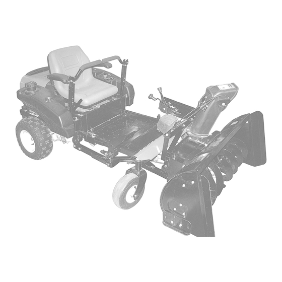
PARTS LIST FRAME ASSEMBLY OEe001 GB - 24... -
Page 25: Bolt, Round Head Square Neck .31-18 X .75 Grade
FRAME ASSEMBLY (CONTINUED) Item Part No. Qty. Description 05958400 Hex Bolt, .38-16 x 2.50 Grade 5 03788751 Plate, Sno-Thro Mount 06536300 Nut, Locking, Center .50-13 06542000 Nut, Locking, Top, Flange .38-16 00264551 Plate, Shim 05957800 Bolt, Hex .38-16 x 3.00 Grade 5 00260351 Plate, Subframe 00263751... - Page 26 REDUCTION DRIVE ASSEMBLY 17 33 OEe003 GB - 26...
-
Page 27: Weldment, Idler
REDUCTION DRIVE ASSEMBLY (CONTINUED) Item Part No. Qty. Description 05946800 Bolt, Hex .25-20 x .75 Grade 5 06308400 Washer, Locking .25 x .062 Regular 06446300 Washer, Flat Steel .344 x 1.125 x .135 06530400 Nut, Spin Lock Flange .312-18 07307000 Pulley, V 9.0 x 1.25 06444200 Washer, Flat Steel .755 x 1.25 x .125... - Page 28 SNOW CHUTE AND CHUTE CRANK ASSEMBLY 19 16 15 16 28 11 OEe005 GB - 28...
- Page 29 SNOW CHUTE AND CHUTE CRANK ASSEMBLY (CONTINUED) Item Ariens Part No. Agri-Fab Part No. Qty. Description 01019800 Cap, .38 Rod 07508300 Knob 603-0302 Assembly, Chute Tilt Bracket 06215700 Bolt, Round Head Square Neck .31-18 x .75 Grade 5 720-0232 Knob...
- Page 30 SNOW THROWER AND AUGER ASSEMBLY 14 13 17 18 OEe005 GB - 30...
- Page 31 SNOW THROWER AND AUGER ASSEMBLY (CONTINUED) Item Ariens Part No. Agri-Fab Part No. Qty. Description 05960300 44377 Hex Bolt, 3/8-24 X 1 06308800 43003 Lock Washer, 3/8 06436200 736-0247 Washer 47026 Pulley, V-Type 06529800 43064 Hex Lock Nut, 5/16-18 06308600...
-
Page 32: Top Locking
WHEELS AND COUNTERWEIGHTS Item Part No. Qty. Description 05962200 Bolt, Hex .50-13 x 5.00 Grade 5 00272000 Reflector 47788 (Agri-Fab Part Number) 05958000 Bolt, Hex .38-16 x 1.25 Grade 5 03789051 Bracket, Weight 06543600 Nut, Top Locking Flange .50-13 06542000 Nut, Top Locking Flange .38-16 00259000 Assembly, Wheel and Tire, Snow Hog 18 x 6.5... -
Page 33: Warranty
Register the product immediately at the time of sale. If the dealer does not register the product, the customer must complete the product registration card in the literature package and return it to the Ariens Company, or register the unit online at www.ariens.com, www.gravely.com, www.countax.com. - Page 34 Exclusions - Items Not Covered by This Warranty • Parts that are not genuine Ariens, Gravely or Countax service parts are not covered by this warranty and may void the warranty. • Damages resulting from the installation or use of any part, accessory, or attachment which is not approved by the Ariens Company for use with product(s) identified herein are not covered by this warranty.
- Page 36 Ariens GRAVELY 655 West Ryan Street Brillion, WI 54110 920-756-4688 Fax 920-756-2407 www.ariens.com...
Need help?
Do you have a question about the 815034 and is the answer not in the manual?
Questions and answers