Advertisement
Owner's Manual
CAUTION:
Weight on this product should not exceed 114 kgs.
WARNING
Exercise can present a health risk.
Consult a physician before beginning
any exercise program with this
equipment. If you feel faint or dizzy,
immediately discontinue use of this
equipment. Serious bodily injury can
occur if this equipment is not
assembled and used correctly.
Serious bodily injury can also occur if
all instructions are not followed. Keep
others and pets away from equipment
when in use. Always make sure all
bolts and nuts are tightened prior to
each use. Follow all safety instructions
in this manual.
Product May Vary Slightly
From Pictured.
I
Advertisement
Table of Contents

Related Manuals for Orbit Fitness T6610


Summary of Contents for Orbit Fitness T6610
-
Page 1: Keep Children Away From The 2 In 1 Rower / Recumbent Bike. Do Not Allow Children To Use Or Play On The 2 In
Owner’s Manual WARNING Exercise can present a health risk. Consult a physician before beginning any exercise program with this equipment. If you feel faint or dizzy, immediately discontinue use of this equipment. Serious bodily injury can occur if this equipment is not assembled and used correctly. -
Page 2: Table Of Contents
TABLE OF CONTENTS Page Page Safety Instructions Maintenance Assembly Instructions Storage Using The Electronic Meter Product Parts Drawing Operational Instructions Parts List SAFETY INSTRUCTIONS WARNING: To reduce the risk of serious injury, read the following Safety Instructions before using the 2 in 1 Rower / Recumbent Bike. -
Page 3: Assembly Instructions
ASSEMBLY INSTRUCTIONS Place all parts form the box in a cleared area and position them on the floor in front of you. Remove all packing materials from your area and place them back into the box. Do not dispose of the packing materials until assembly is completed. - Page 4 ASSEMBLY INSTRUCTIONS STEP 4: Attach the SUPPORT BRACKET(60) onto the RAIL(52) with HEX BOLTS(M8x16mm)(97). Press the NUT CAPS(79) onto NYLOCK NUT(M10)(105) and HEX BOLTM10x75mm (100). STEP 5: Attach the RAIL(52) onto the MAIN FRAME(1) by sliding the RAIL PIVOT(49) into the bracket on the MAIN FRAME(1) and securing with HEX BOLT (M10125mm)(103) and NYLOCK NUT(M10)(105).
- Page 5 ASSEMBLY INSTRUCTIONS NOTE: Be careful not to damage the PULSE SENSOR WIRES(73,74) while doing assembly STEP 8 to STEP 10. STEP 8: Attach the HANDRAIL(70) onto the SEAT CARRIAGE(64) with BUTTON HEAD BOLTS (M8x12mm)(114). STEP 9: Attach the SEAT(68) onto the SEAT CARRIAGE(64) with HEX BOLTS(M6x15mm)(95). Attach the BACK CUSHION(69) onto the SEAT CARRIAGE(64) with HEX BOLTS (M6x30mm)(96).
- Page 6 ASSEMBLY INSTRUCTIONS NOTE: The RIGHT PEDAL(41) has R stamped on the end of the pedal shaft. The RIGHT PEDAL(41) has right hand threads and is tightened by turning clockwise. The LEFT PEDAL(39) has L stamped on the end of the pedal shaft. The LEFT PEDAL(39) has left hand threads and is tightened by turning counter clockwise.
- Page 7 ASSEMBLY INSTRUCTIONS STEP 13: Insert the SENSOR WIRE(29) and PULSE CONNECTION WIRE(75) into the bottom end of METER POST(31) and pull them out of the top of the METER POST(31). Pull the HANDLEBAR(25), twist the STRAP(21) and slide the strap thru the gap into the hole in the bottom of the METER POST(31).
-
Page 8: Using The Electronic Meter
USING THE ELCETRONIC METER BC-81268 PROGRAM INTRODUCTION: Manual Program: Manual PROGRAM 1 is a manual program. Press “ENTER” key to select TIME, DISTANCE and CAL. Then, Press ”UP” or ”DOWN” key to adjust the values. After pressing “START/STOP” key to exercise, please also apply the heart rate detector appropriately. - Page 9 decrease while the speed is too fast. As a result, the calculated value of WATT will close to the value of WATT setup by users. Heart Rate Control Programs: 60% H.R.C. (Heart Rate Control Program), 75% H.R.C., 85% H.R.C. Program 10 to Program 12 is the Heart Rate Control Programs. In Program 10 to Program 12, press “Enter” key to select TIME, DISTANCE, Cal &...
- Page 10 RECOVERY Press this button to enter the fitness test. The ranking of the test resolute is from F1.0 to F6.0. USER Press this button to the personal data input. ENTER 1. During the program choosing function, press this button to confirm the program you would like to do the exercise.
- Page 11 DOWN The distance display will flash, and then press “ ” or ” ” button to set up the desired distance value. Press ENTER button to confirm your setting value. DOWN The Calories display will flash, and then press “ ”...
- Page 12 2. Time and distance cannot set up at the same time in this program. 3. When you reach the target, the monitor will produce beep sound and then stop. 4. If you set up more than one target and you would like to reach next target, press start to exercise again.
- Page 13 C-6 Body fat measurement DOWN 1. Press “ ” or ” ” button to select BODY FAT TEST program, Press the ENTER Button to confirm your choice. DOWN 2. The HEIGHT display will flash, and then press “ ” or ” ”...
-
Page 14: Operational Instructions
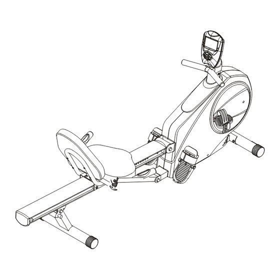
OPERATIONAL INSTRUCTIONS RECUMBENT BIKE MODE AND ROWER MODE Your 2 in 1 Rower / Recumbent Bike can be used in the Recumbent Bike mode or the Rower mode. When the SPRING PIN(67) locks the SEAT ASSEMBLY to the RAIL(52), the 2 in 1 Rower/ Recumbent Bike is in the Recumbent Bike mode. -
Page 15: Maintenance
OPERATIONAL INSTRUCTIONS MAINTENANCE The safety and integrity designed into the 2 in 1 Rower / Recumbent Bike can only be maintained when the 2 in 1 Rower / Recumbent Bike is regularly examined for damage and wear. Special attention should be given to the following: 1. -
Page 16: Storage
STORAGE 1. To store the 2 in 1 Rower / Recumbent Bike simply keep it in a clean dry place. 2. To avoid damage to the electronics meter, remove the batteries before storing the 2 in 1 Rower / Recumbent Bike for one year or more. 3. -
Page 18: Parts List
PARTS LIST PART NAME PART NAME Main Frame Left Pedal Strap Front Stabilizer Right Pedal Axle Right Pedal Strap Pulley Stand Strap Wheel Pedal Shaft Connection Wheel Spacer Free Wheel Foot Pedal Bearing (6004Z) Pedal Strap C Ring M20 Stopper Tube Bearing Housing Rail Pivot V-Ribbed Belt... - Page 19 PART NAME Nut Cap M10 Carriage Bolt M8x1.25x60mm Carriage Bolt M8x1.25x70mm Screw, Round Head M4x20mm Screw, Round Head M4x25mm Screw, Round Head M5x18mm Screw, Round Head M5x0.8x15mm Screw, Round Head M5x0.8x18mm Bolt, Socket Head M5x0.8x15mm Bolt, Round Head M6x1x15mm Bolt, Round Head M6x1x30mm Bolt, Flat Head M8x1.25x16mm Bolt, Flat Head M8x1.25x25mm Bolt, Flat Button Head M8x1.25x25mm...
Need help?
Do you have a question about the T6610 and is the answer not in the manual?
Questions and answers