Table of Contents
Advertisement
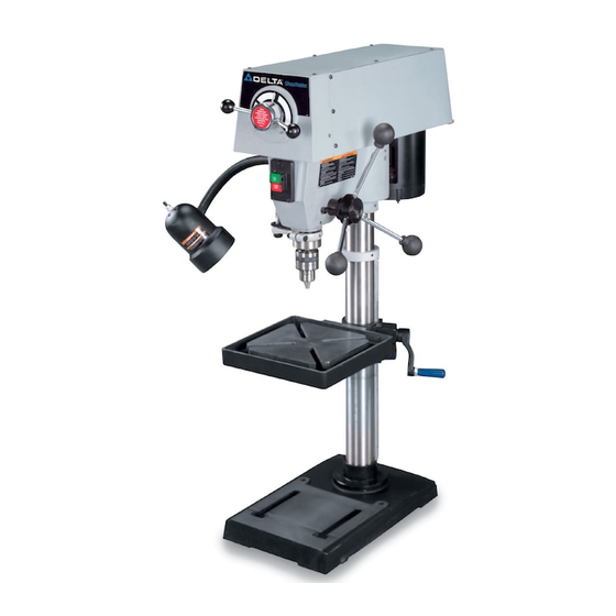
12" Variable Speed Drill Press
(Model DP350)
PART NO. A05751 - 06-22-05
Copyright © 2005 Delta Machinery
To learn more about DELTA MACHINERY
ESPAÑOL: PÁGINA 19
visit our website at: www.deltamachinery.com.
For Parts, Service, Warranty or other Assistance,
1-800-223-7278 (
1-800-463-3582).
please call
In Canada call
Advertisement
Table of Contents

Related Manuals for Delta DP350


Summary of Contents for Delta DP350
- Page 1 12" Variable Speed Drill Press (Model DP350) PART NO. A05751 - 06-22-05 Copyright © 2005 Delta Machinery To learn more about DELTA MACHINERY ESPAÑOL: PÁGINA 19 visit our website at: www.deltamachinery.com. For Parts, Service, Warranty or other Assistance, 1-800-223-7278 ( 1-800-463-3582).
-
Page 2: Table Of Contents
NOT be modified and/or used for any application other than for which it was designed. If you have any questions relative to its application DO NOT use the product until you have written Delta Machinery and we have advised you. -
Page 3: Safety Guidelines
SAFETY GUIDELINES - DEFINITIONS It is important for you to read and understand this manual. The information it contains relates to protecting YOUR SAFETY and PREVENTING PROBLEMS. The symbols below are used to help you recognize this information. Indicates an imminently hazardous situation which, if not avoided, will result in death or serious injury. Indicates a potentially hazardous situation which, if not avoided, could result in death or serious injury. -
Page 4: General Safety Rules
Damage to the machine and/or injury may result. water. 13. USE RECOMMENDED ACCESSORIES. The use of accessories and attachments not recommended by Delta may cause damage to the machine or injury to the user. -
Page 5: Additional Specific Safety Rules
ADDITIONAL SPECIFIC SAFETY RULES FAILURE TO FOLLOW THESE RULES MAY RESULT IN SERIOUS INJURY. DO NOT OPERATE THIS MACHINE until it is 13. AVOID AWKWARD OPERATIONS AND HAND completely assembled and installed according to POSITIONS. A sudden slip could cause a hand to the instructions. -
Page 6: Grounding Instructions
POWER CONNECTIONS A separate electrical circuit should be used for your machines. This circuit should not be less than #12 wire and should be protected with a 20 Amp time lag fuse. If an extension cord is used, use only 3-wire extension cords which have 3-prong grounding type plugs and matching receptacle which will accept the machine’s plug. -
Page 7: Functional Description
FUNCTIONAL DESCRIPTION FOREWORD Delta ShopMaster Model DP350 is a 12" variable speed bench drill press with a flexible work lamp that allows you to quickly and easily change the drill speeds without removing the cover and adjusting belts. NOTICE: The photo on the manual cover illustrates the current production model. All other illustrations contained in the manual are representative only and may not depict the actual labeling or accessories included. -
Page 8: Assembly
UNPACKING AND CLEANING Carefully unpack the machine and all loose items from the shipping container(s). Remove the protective coating from all unpainted surfaces. This coating may be removed with a soft cloth moistened with kerosene (do not use acetone, gasoline or lacquer thinner for this purpose). After cleaning, cover the unpainted surfaces with a good quality household floor paste wax. - Page 9 3. Insert raising rack (F) Fig. 6, which was removed in STEP 1, into groove in table bracket making sure teeth of worm gear (G) located inside table bracket are engaged with teeth of raising rack (F). Fig. 6 4. Slide raising rack (F) Fig. 7, table and table bracket onto drill press column, as shown. Make sure bottom of raising rack (F) Fig.
- Page 10 7. Thread stud on clamp handle (M) Fig. 12, into hole in rear of table bracket, as shown. Fig. 12 8. Place the drill press head (N) Fig. 13, onto the column as far as it will go. Align head (A) Fig. 13A, to table (B), and base (C).
-
Page 11: Operation
10. IMPORTANT: Make certain the spindle taper (Q) Fig. 15, and tapered hole in chuck (R) are clean and free of any grease, lacquer or rust preventive coatings. NOTE: Household oven cleaner can effectively remove any substance from the spindle and chuck; however, carefully follow the manufacturer's safety rules concerning its use. 11. -
Page 12: Table Adjustments
FLEXIBLE LAMP The flexible lamp operates independently of the drill press. To turn the lamp “ON” and “OFF”, rotate switch (A) Fig. 18A. To reduce the risk of fire, use 40 watt or less, 120 volt, reflector track type light bulb (not supplied). -
Page 13: Drilling Holes To Depth
VARIABLE SPEED CONTROL To avoid damaging the drive belts and pulleys, DO NOT turn speed control handles (A) Fig. 24, unless motor is running. The pilot wheel handles (A) are turned clockwise to increase speed and counterclockwise to decrease speed. The speed range is 500 rpm to 3100 rpm. -
Page 14: Adjusting Spindle Return Spring
Use scrap material for practice to get a feel of the machine before attempting regular work. The use of accessories and attachments not recommended by Delta may result in risk of injury. IMPORTANT: When the workpiece is long enough it should always be positioned on the table with one end against the left side of the column, as shown in Fig. -
Page 15: Troubleshooting
If the piece is of irregular shape and cannot be laid flat on the table, it should be securely blocked and clamped. TROUBLESHOOTING For assistance with your machine, visit our website at www.deltamachinery.com for a list of service centers or call the DELTA Machinery help line at 1-800-223-7278 (In Canada call 1-800-463-3582). -
Page 16: Maintenance
MAINTENANCE LUBRICATION DISCONNECT MACHINE FROM POWER SOURCE. 1. Remove the six screws (A) Fig. 30 that hold the top cover in place, and remove the top cover. 2. The variable speed pulleys should be oiled weekly Fig. 30 with a few drops of light machine oil in the two oil holes (B) Fig. -
Page 17: Service
SERVICE PARTS, SERVICE OR WARRANTY ASSISTANCE All Delta Machines and accessories are manufactured to high quality standards and are serviced by a network • of Porter-Cable Delta Factory Service Centers and Delta Authorized Service Stations. To obtain additional information regarding your Delta quality product or to obtain parts, service, warranty assistance, or the location of the nearest service outlet, please call 1-800-223-7278 (In Canada call 1-800-463-3582). -
Page 18: Warranty
Two Year Limited New Product Warranty Delta will repair or replace, at its expense and at its option, any new Delta machine, machine part, or machine accessory which in normal use has proven to be defective in workmanship or material, provided that the customer returns the product prepaid to a Delta factory service center or authorized service station with proof of purchase of the product within two years and provides Delta with reasonable opportunity to verify the alleged defect by inspection. -
Page 19: Español
Fax: (519) 767-4131 Fax: (604) 420-3522 Fax: (514) 336-3505 The following are trademarks of PORTER-CABLE • DELTA (Las siguientes son marcas registradas de PORTER-CABLE • DELTA S.A.) (Les marques suivantes sont des marques de fabriquant de la PORTER-CABLE • DELTA): Auto-Set ®...
Need help?
Do you have a question about the DP350 and is the answer not in the manual?
Questions and answers