Table of Contents
Advertisement
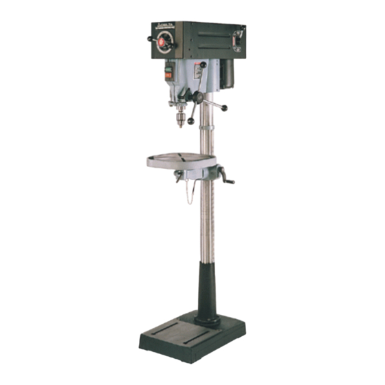
16-1/2" Variable Speed
Drill Press
(Model 17-925)
(Model 17-990X)
MODEL 17-925
PART NO. A10354 - 04-06-05
Copyright © 2005 Delta Machinery
To learn more about DELTA MACHINERY
visit our website at: www.deltamachinery.com.
For Parts, Service, Warranty or other Assistance,
1-800-223-7278 (
1-800-463-3582).
please call
In Canada call
Advertisement
Table of Contents

Subscribe to Our Youtube Channel
Related Manuals for Delta 17-925


Summary of Contents for Delta 17-925
- Page 1 Drill Press (Model 17-925) (Model 17-990X) MODEL 17-925 PART NO. A10354 - 04-06-05 Copyright © 2005 Delta Machinery To learn more about DELTA MACHINERY visit our website at: www.deltamachinery.com. For Parts, Service, Warranty or other Assistance, 1-800-223-7278 ( 1-800-463-3582). please call...
-
Page 2: Table Of Contents
NOT be modified and/or used for any application other than for which it was designed. If you have any questions relative to its application DO NOT use the product until you have written Delta Machinery and we have advised you. -
Page 3: Safety Guidelines
SAFETY GUIDELINES - DEFINITIONS It is important for you to read and understand this manual. The information it contains relates to protecting YOUR SAFETY and PREVENTING PROBLEMS. The symbols below are used to help you recognize this information. Indicates an imminently hazardous situation which, if not avoided, will result in death or serious injury. Indicates a potentially hazardous situation which, if not avoided, could result in death or serious injury. -
Page 4: General Safety Rules
GENERAL SAFETY RULES IMPORTANT SAFETY INSTRUCTIONS 13. USE RECOMMENDED ACCESSORIES. The use of accessories and attachments not recommended by Delta may cause damage to the machine or injury to the user. 14. USE THE PROPER EXTENSION CORD. Make sure your extension cord is in good condition. -
Page 5: Additional Specific Safety Rules
BIT, CUTTING TOOL, OR SANDING DRUM TO STOP TURNING prior to cleaning the work area, removing debris, removing or securing work-piece, or changing the angle of the table. A moving drill bit, cutting tool, or sanding drum can cause serious injury. PROPERLY SUPPORT LONG OR WIDE work-pieces. -
Page 6: Grounding Instructions
230 volts. If the drill press must be reconnected for use on a different type of electrical circuit, the re-connection should be made by qualified service personnel; and after re-connection, the tool should comply with all local codes and ordinances. -
Page 7: Functional Description
EXTENSION CORDS Use proper extension cords. Make sure your extension cord is in good condition and is a 3-wire extension cord which has a 3-prong grounding type plug and matching receptacle which will accept the machine’s plug. When using an extension cord, be sure to use one heavy enough to carry the current of the machine. An undersized cord will cause a drop in line voltage, resulting in loss of power and overheating. - Page 8 Worm for Table-Raising Mechanism Table-Raising and Lowering Handwheel Table Chuck Chuck Key 11A. Pinion Shaft Handles (3) (For model 17-925 ONLY) 11B. Pinion Shaft Handle (For Model 17-990X ONLY) Speed Range Changing Lever Speed Changing Levers (2) Base M8 x 125mm Carriage Head Screw (2), M8 Flat Washer (2), M8.1 Lock Washer (2),...
-
Page 9: Assembly
Fig. 4 4. Slide the raising rack (F) Fig. 7 and table bracket (J) on the drill press column. Make certain that the bottom of the raising rack (F) Fig. 8 is engaged with the flange (K) on the drill press base. - Page 10 5. Re-install the ring (E) Fig. 9 (removed in STEP 1). IMPORTANT: DO NOT push the ring (E) Fig. 9 all the way down on the the raising rack (F). Make certain that the top of the raising rack (F) is under the bottom of the ring (E) and that enough .9376tk[148 659.602 44 -13.25 39.75wn ou6TD-04ET(Attace set t266 Tadjusts unhe b6 T(K078 0 TD25 le the orm geno shaftT(G the bot clearance is available to allow the rack (F) to rotate around the...
- Page 11 To avoid damage to the chuck, NEVER drive the chuck onto the spindle with a metal hammer. Fig. 16 FOR MODEL 17-925 ONLY Thread the three pinion shaft handles (U) in the three holes located in the pinion shaft hub (V) (Fig. 18).
- Page 12 Use a good grade of 3/4" or thicker plywood. DO NOT make the mounting board from particle board. Start with a 21" x 28" or larger piece of plywood. Drill two 3/8" diameter holes (B) Fig. 25 that match the mounting holes (A) Fig.
-
Page 13: Operation
OPERATIONAL CONTROLS AND ADJUSTMENTS STARTING AND STOPPING THE DRILL PRESS The on/off switches (A and B) Fig. 27 are located on the front of the drill press. To turn the machine “ON”, depress the “START” switch. To turn the machine “OFF”, depress the “STOP” switch. - Page 14 Fig. 32 DRILLING HOLES TO DEPTH When you want to drill a number of holes to the same depth, use the stop nut (A) Fig. 34 on the threaded stop rod (B). DISCONNECT MACHINE FROM POWER SOURCE. Insert the bit into the chuck.
-
Page 15: Adjusting The Spindle Return Spring
NOTE: After installing a drill bit, use the supplied key to tighten all three locations on the chuck. The use of accessories and attachments not recommended by Delta may result in risk of injury. IMPORTANT: When the workpiece (B) Fig. 38 is long enough, position it on the table with one end against the left side of the column (C) to prevent the workpiece from rotating. -
Page 16: Installing And Removing Drill Bits
DISCONNECT MACHINE FROM POWER 1. Insert the smooth end of drill bit (A) Fig. 39 in the chuck (B) as far as it will go, and then back the bit out 1/16" (or up to the flutes for small bits). -
Page 17: Troubleshooting
(A) Fig. 38, located on top of the variable speed pulleys, and the hole (B), located on top of the shifter mechanism. IMPORTANT: Oil the holes when the drill press is turned "OFF". After lubricating, turn the machine "ON" and run the machine through its low and high speed ranges several times. -
Page 18: Service
Also, check for blown fuses or open circuit breakers in the line. PARTS, SERVICE OR WARRANTY ASSISTANCE All Delta Machines and accessories are manufactured to high quality standards and are serviced by a network • of Porter-Cable Delta Factory Service Centers and Delta Authorized Service Stations. To obtain additional information regarding your Delta quality product or to obtain parts, service, warranty assistance, or the location of the nearest service outlet, please call 1-800-223-7278 (In Canada call 1-800-463-3582). -
Page 19: Warranty
Two Year Limited New Product Warranty Delta will repair or replace, at its expense and at its option, any new Delta machine, machine part, or machine accessory which in normal use has proven to be defective in workmanship or material, provided that the customer returns the product prepaid to a Delta factory service center or authorized service station with proof of purchase of the product within two years and provides Delta with reasonable opportunity to verify the alleged defect by inspection. - Page 20 Phone: (604) 420-0102 Fax: (604) 420-3522 The following are trademarks of PORTER-CABLE • DELTA (Las siguientes son marcas registradas de PORTER-CABLE • DELTA S.A.) (Les marques suivantes sont des marques de fabriquant de la PORTER-CABLE • DELTA): Auto-Set Contractor’s Saw II™, Delta ®...
Need help?
Do you have a question about the 17-925 and is the answer not in the manual?
Questions and answers