Advertisement
Table of Contents
Safe Operation Practices • Set-Up • Operation • Maintenance • Service • Troubleshooting • Warranty
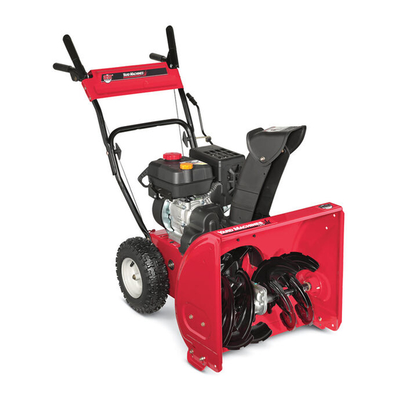
OPERATOR'S MANUAL
Two-Stage Snow Thrower
WARNING
READ AND FOLLOW ALL SAFETY RULES AND INSTRUCTIONS IN THIS MANUAL
BEFORE ATTEMPTING TO OPERATE THIS MACHINE.
FAILURE TO COMPLY WITH THESE INSTRUCTIONS MAY RESULT IN PERSONAL INJURY.
P. O. Box 1386, 97 KENT AVENUE, KITCHENER, ON N2G 4J1
Printed In USA
769-06354B
05.28.14
Advertisement
Table of Contents

Related Manuals for Yard Machines 769-06354


Summary of Contents for Yard Machines 769-06354
- Page 1 Safe Operation Practices • Set-Up • Operation • Maintenance • Service • Troubleshooting • Warranty OPERATOR’S MANUAL Two-Stage Snow Thrower WARNING READ AND FOLLOW ALL SAFETY RULES AND INSTRUCTIONS IN THIS MANUAL BEFORE ATTEMPTING TO OPERATE THIS MACHINE. FAILURE TO COMPLY WITH THESE INSTRUCTIONS MAY RESULT IN PERSONAL INJURY. P.
-
Page 2: Table Of Contents
To The Owner Thank You Thank you for purchasing your new equipment. It was carefully The manufacturer reserves the right to change product engineered to provide excellent performance when properly specifications, designs and equipment without notice and operated and maintained. without incurring obligation. -
Page 3: Important Safe Operation Practices
Important Safe Operation Practices WARNING! This symbol points out important safety instructions which, if not followed, could endanger the personal safety and/or property of yourself and others. Read and follow all instructions in this manual before attempting to operate this machine. Failure to comply with these instructions may result in personal injury. - Page 4 Safe Handling of Gasoline Never run an engine indoors or in a poorly ventilated area. Engine exhaust contains carbon monoxide, an odorless To avoid personal injury or property damage use extreme care and deadly gas. in handling gasoline. Gasoline is extremely flammable and the Do not operate machine while under the influence of vapors are explosive.
- Page 5 Clearing a Clogged Discharge Chute According to the Consumer Products Safety Commission (CPSC) and the U.S. Environmental Protection Agency (EPA), Hand contact with the rotating impeller inside the discharge this product has an Average Useful Life of seven (7) years, chute is the most common cause of injury associated with snow or 60 hours of operation.
-
Page 6: Safety Symbols
Safety Symbols This page depicts and describes safety symbols that may appear on this product. Read, understand, and follow all instructions on the machine before attempting to assemble and operate. Symbol Description READ THE OPERATOR’S MANUAL(S) Read, understand, and follow all instructions in the manual(s) before attempting to assemble and operate WARNING—... -
Page 7: Assembly & Set-Up
Assembly & Set-Up IMPORTANT: The snow thrower is shipped with oil and WITHOUT GASOLINE. After assembly, refer to separate engine manual for proper fuel and engine oil recommendations. NOTE: Remove all loose parts and any packing material before assembling. NOTE: References to right or left side of the snow thrower are determined from behind the unit in the operating position. NOTE: This Operator’s Manual covers several models, handle panels, lights and chute cranks are some features that may vary by model. - Page 8 IMPORTANT: Prior to operating your snow thrower, refer to Close the flange keepers to secure the chute assembly to the chute base. The flange keepers will click into place Auger Control Test on page 11. Read and follow all instructions when properly secure.
- Page 9 Clean-Out Tool Lamp Wiring Harness (If equipped) The clean-out tool is mounted to the rear of the auger housing The post on the cable tie attaching the lamp wiring harness to and is designed to clear a clogged chute. Refer to page 13 for the lower handle should be plugged into the hole in the lower instructions on how to properly use it.
- Page 10 Adjustment Skid Shoes The snow thrower skid shoes are adjusted upward at the factory Chute Assembly for shipping purposes. Adjust them downward, if desired, prior The distance snow is thrown can be adjusted by changing the to operating the snow thrower. angle of the chute assembly.
- Page 11 Fig. 3-13 Fig. 3-12 NOTE: Some models are equipped with reversible skid shoes Allow the auger to remain engaged for approximately ten and may be turned over to increase their lifespan. (10) seconds before releasing the auger control. Repeat this several times.
-
Page 12: Controls
Controls and Features Drive Control Auger Control Chute Directional Control Chute Assembly Chute Clean Out Tool Skid Shoe Augers Fig. 4-1 Chute Directional Control Snow thrower controls and features are described below and illustrated in Fig. 4-1. The chute directional control can be turned clockwise or Skid Shoes counterclockwise to change the direction in which snow is thrown. -
Page 13: Auger Control
Auger Control Chute Clean-Out Tool WARNING! Never use your hands to clear a clogged chute assembly. Shut off engine and remain behind handles until all moving parts have stopped before unclogging. The chute clean-out tool is conveniently fastened to the rear of the auger housing with a mounting clip. -
Page 14: Operation
Operation Starting and Stopping the Engine Replacing Shear Pins Refer to the Engine Operator’s Manual packed with your snow The augers are secured to the spiral shaft with two shear thrower for instructions on starting and stopping the engine. pins and cotter pins. If the auger should strike a foreign object or ice jam, the snow thrower is designed so that the To Engage Drive pins may shear. -
Page 15: Maintenance & Adjustment
Maintenance & Adjustments Maintenance Lubrication Engine Wheels Refer to the Engine Operator’s Manual packed with your snow At least once a season, remove both wheels. Clean and coat the thrower. axles with a multipurpose automotive grease before reinstalling wheels. Tire Pressure Auger Shaft Refer to “Assembly &... - Page 16 Adjustments Off-Season Storage If the snow thrower will not be used for 30 days or longer, follow Auger Control the storage instructions below. Refer to the Assembly & Set-up section for instructions on Lubricate the machine as instructed earlier in this section. adjusting the auger control cable.
-
Page 17: Service
Service Belt Replacement Roll the auger belt off the engine pulley. See Fig. 7-3. Auger Belt To remove and replace your snow thrower’s auger belt, proceed as follows: Allow the engine to run until it is out of fuel. Do not attempt to pour fuel from the engine. - Page 18 Drive Belt Remove the belt as follows. See Fig. 7-5. Loosen and remove the shoulder bolt which acts as To remove and replace your snow thrower’s drive belt, proceed a belt keeper. as follows: Unhook the brake bracket spring from the frame. To prevent spillage, remove all fuel from tank by running engine until it stops.
- Page 19 Friction Wheel Inspection Back out the stop bolt to increase the clearance between the friction wheel disc and friction wheel. See Fig. 7-8. If the snow thrower fails to drive with the drive control engaged, and performing the drive control cable adjustment fails to correct the problem, the friction wheel may need to be replaced.
-
Page 20: Troubleshooting
Troubleshooting Problem Cause Remedy Engine fails to start Choke not in CHOKE position. Move choke to CHOKE position. Spark plug wire disconnected. Connect wire to spark plug. Fuel tank empty or stale fuel. Fill tank with clean, fresh gasoline. Engine not primed. Prime engine as instructed in the Operation section. -
Page 21: Replacement Parts
Replacement Parts Component Part Number and Description 954-04050A Auger Drive Belt 954-04260 Wheel Drive Belt (24”) 738-04124A Shear Pin, 1.50 714-04040 Bow-tie Cotter Pin 784-5580 Slide Shoe, Standard (Steel) 931-2643 Chute Clean-out Tool 790-00117 Shave Plate, 22” 731-05632 951-10292 Spark Plug NOTE: Download a complete Parts Manual, refer to customer support on page 2. -
Page 22: Warranty
TWO YEAR LIMITED WARRANTY The limited warranty set forth below is given by MTD Products Limited with respect to new merchandise purchased and used in Canada and/or its territories and possessions (either entity respectively, “MTD”). MTD warrants this product (excluding its normal wear parts as described below) against defects in material and workmanship for a period of two (2) years commencing on the date of original purchase and will, at its option, repair or replace, free of charge, any part found to be defective in materials or workmanship.
Need help?
Do you have a question about the 769-06354 and is the answer not in the manual?
Questions and answers