Advertisement
Available languages
Available languages
Quick Links
Safe Operation Practices • Set-Up • Operation • Maintenance • Service • Troubleshooting • Warranty
O
'
M
peratOr
s
anual
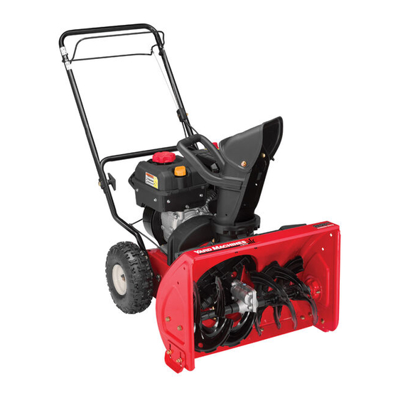
Two-Stage Snow Thrower — 300 Series
WARNING
READ AND FOLLOW ALL SAFETY RULES AND INSTRUCTIONS IN THIS MANUAL
BEFORE ATTEMPTING TO OPERATE THIS MACHINE.
FAILURE TO COMPLY WITH THESE INSTRUCTIONS MAY RESULT IN PERSONAL INJURY.
MTD LLC, P.O. BOX 361131 CLEVELAND, OHIO 44136-0019
Printed In USA
Form No. 769-06918
(February 1, 2011)
Advertisement

Related Manuals for Yard Machines 31A-32AD752


Summary of Contents for Yard Machines 31A-32AD752
- Page 1 Safe Operation Practices • Set-Up • Operation • Maintenance • Service • Troubleshooting • Warranty ’ peratOr anual Two-Stage Snow Thrower — 300 Series WARNING READ AND FOLLOW ALL SAFETY RULES AND INSTRUCTIONS IN THIS MANUAL BEFORE ATTEMPTING TO OPERATE THIS MACHINE. FAILURE TO COMPLY WITH THESE INSTRUCTIONS MAY RESULT IN PERSONAL INJURY.
- Page 2 To The Owner Thank You Thank you for purchasing a Snow Thrower manufactured by If you have any problems or questions concerning the unit, MTD LLC. It was carefully engineered to provide excellent phone your local authorized MTD service dealer or contact us performance when properly operated and maintained.
- Page 3 Important Safe Operation Practices WARNING! This symbol points out important safety instructions which, if not followed, could endanger the personal safety and/or property of yourself and others. Read and follow all instructions in this manual before attempting to operate this machine. Failure to comply with these instructions may result in personal injury.
- Page 4 Safe Handling of Gasoline Never run an engine indoors or in a poorly ventilated area. Engine exhaust contains carbon monoxide, an odorless To avoid personal injury or property damage use extreme care and deadly gas. in handling gasoline. Gasoline is extremely flammable and the Do not operate machine while under the influence of vapors are explosive.
- Page 5 Clearing a Clogged Discharge Chute According to the Consumer Products Safety Commission (CPSC) and the U.S. Environmental Protection Agency (EPA), Hand contact with the rotating impeller inside the discharge this product has an Average Useful Life of seven (7) years, chute is the most common cause of injury associated with snow or 60 hours of operation.
- Page 6 Safety Symbols This page depicts and describes safety symbols that may appear on this product. Read, understand, and follow all instructions on the machine before attempting to assemble and operate. Symbol Description READ THE OPERATOR’S MANUAL(S) Read, understand, and follow all instructions in the manual(s) before attempting to assemble and operate WARNING—...
- Page 7 Assembly & Set-Up Contents of Carton • One Snow Thrower • Two Replacement Auger Shear Pins • One Engine Operator’s Manual • One Snow Thrower Operator’s • One Product Registration Card Manual Assembly Setting Up The Handle Remove cable tie (if present) securing upper handle to lower handle for shipping purposes.
- Page 8 Set-Up Tire Pressure WARNING: Under any circumstance do not exceed Shear Pins manufacturer’s recommended psi. Equal tire A pair of replacement auger shear pins and bow tie cotter pins pressure should be maintained at all times. Excessive are included with your snow thrower. See Fig. 3-4. Store them in pressure when seating beads may cause tire/rim a safe place until needed.
- Page 9 While standing in the operator’s position (behind the snow thrower) engage the auger. Allow the auger to remain engaged for approximately 10 seconds before releasing the auger control. Repeat this several times. With the engine running in the FAST position and the auger control in the disengaged “up”...
- Page 10 Controls and Features Upper Handle Auger Control Drive Control Starter Rope Gasoline Cap Chute Handle Upper Chute Chute Assembly Clean-out Tool Chute Knob Auger Shave Plate Skid Shoe Figure 4-1 Snow thrower controls and features are described below and Auger Control illustrated in Fig.
- Page 11 Shave Plate The shave plate maintains contact with pavement as the snow thrower is propelled, allowing snow close to pavement’s surface to be discharged. Skid Shoes Position the skid shoes based on surface conditions. Adjust upward for hard-packed snow. Adjust downward when operating on gravel or crushed rock surfaces.
- Page 12 Operation Starting The Engine Replacing Shear Pins Refer to the Operation section of the engine operator’s manual The augers are secured to the spiral shaft with two shear pins included with the snow thrower. and cotter pins. If the auger should strike a foreign object or ice jam, the snow thrower is designed so that the pins may shear.
- Page 13 Maintenance & Adjustments Maintenance Shave Plate and Skid Shoes The shave plate and skid shoes on the bottom of the snow General Recommendations thrower are subject to wear. These should be checked • Always observe safety rules when performing any type of periodically and replaced when necessary.
- Page 14 Preparing The Engine Auger Shaft IMPORTANT: At least once a season, remove the shear pins from the auger Refer to the engine operator’s manual shaft. Spray lubricant inside the shaft and around the spacers and included with the snow thrower for complete engine servicing the flange bearings found at either end of the shaft.
- Page 15 Service Augers Auger Belt Tip the snow thrower up and forward so that it rests on The augers are secured to the spiral shaft with four shear pins and the auger housing. Remove the belt keeper (Refer to Fig. cotter pins. If you hit a foreign object or ice jam, the snow thrower 7-3).
- Page 16 Drive Belt NOTE: Replace the drive belt before reassembling the new auger belt. Tip the snow thrower up and forward so that it rests on the auger housing. Remove the spring that connects the transmission to a bolt on the engine frame. See Fig. 7-3. NOTE: It may be easier to first remove the flange lock nut, then use needle-nosed pliers to firmly grip spring and remove from bolt.
- Page 17 Troubleshooting Problem Cause Remedy Excessive vibration 1. Loose parts or damaged auger. 1. Stop engine immediately and disconnect spark plug wire. Check for possible damage. Tighten all bolts and nuts. Repair as needed. If the problem persists, take unit to an authorized service dealer.
- Page 18 Replacement Parts Component Part Number and Description 954-04014 Auger Drive Belt 954-04013 Wheel Drive Belt 738-04124A Shear Pin, 1.50 714-04040 Bow-tie Cotter Pin 784-5580 Skid Shoe, Standard (steel) 731-06439 Skid Shoe, Standard (Polymer) 931-2643 Chute Clean-out Tool 790-00117 Shave Plate, 22” Phone (800) 800-7310 to order replacement parts or a complete Parts Manual (have your full model number and serial number ready).
- Page 19 MTD CONSUMER GROUP INC (MTD), the California Air Resources Board (CARB) and the United States Environment Protection Agency (U. S. EPA) Emission Control System Warranty Statement (Owner’s Defect Warranty Rights and Obligations) EMISSION CONTROL SYSTEM COVERAGE IS APPLICABLE TO CERTIFIED ENGINES PURCHASED IN CALIFORNIA IN 2005 AND THERE- AFTER, WHICH ARE USED IN CALIFORNIA, AND TO CERTIFIED MODEL YEAR 2005 AND LATER ENGINES WHICH ARE PURCHASED AND USED ELSEWHERE IN THE UNITED STATES.
- Page 20 (4) Repair or replacement of any warranted part under the warranty provisions of this article must be performed at no charge to the owner at a warranty station. (5) Notwithstanding the provisions of Subsection (4) above, warranty services or repairs must be provided at all MTD distribution centers that are franchised to service the subject engines.
- Page 21 MANUFACTURER’S LIMITED WARRANTY FOR The limited warranty set forth below is given by MTD LLC with c. Service completed by someone other than an authorized service respect to new merchandise purchased and used in the United States dealer. and/or its territories and possessions, and by MTD Products Limited d.
- Page 22 Medidas importantes de seguridad • Configuración • Funcionamiento • Mantenimiento • Servicio • Solución de problemas • Garantía anual del operador Máquina quitanieve de dos etapas — Serie 300 ADVERTENCIA LEA Y SIGA TODAS LAS INSTRUCCIONES DE ESTE MANUAL ANTES DE PONER EN FUNCIONAMIENTO ESTA MÁQUINA.
- Page 23 Al propietario Gracias Gracias por comprar una máquina quitanieve fabricada por MTD estándar sin previo aviso y sin generar responsabilidad por LLC. La misma ha sido diseñada cuidadosamente para brindar obligaciones de ningún tipo. excelente rendimiento si se la opera y mantiene correctamente. Si tiene algún problema o duda respecto a la unidad, llame a un Por favor lea todo este manual antes de operar el equipo.
- Page 24 Medidas importantes de seguridad ADVERTENCIA! ¡ La presencia de este símbolo indica que se trata de instrucciones importantes de seguridad que se deben respetar para evitar poner en peligro su seguridad personal y/o material y la de otras personas. Lea y siga todas las instrucciones de este manual antes de poner en funcionamiento esta máquina.
- Page 25 Nunca intente realizar ajustes mientras el motor está La palanca de control de la barrena / impulsor es un dispositivo de seguridad. Nunca evite su funcionamiento. en marcha excepto en los casos específicamente De hacerlo la operación de la máquina es riesgosa y puede recomendados en el manual del operador.
- Page 26 Para encender el motor, jale de la cuerda lentamente hasta Verifique frecuentemente la línea de combustible, el que sienta resistencia, luego jale rápidamente. El repliegue tanque, el tapón, y los accesorios buscando rajaduras o rápido de la cuerda de arranque (tensión de retroceso) le pérdidas.
- Page 27 Símbolos de Seguridad Esta página describe los símbolos y figuras de seguridad internacionales que pueden aparecer en este producto. Lea el manual del operador para obtener la información terminada sobre seguridad, reunirse, operación y mantenimiento y reparación. Símbolo Descripción LEA EL MANUAL DEL OPERADOR (S) Lea, entienda, y siga todas las instrucciones en el manual (es) antes de intentar reunirse y funcionar.
- Page 28 Montaje y Configuración Contenido de la caja • Una máquina quitanieve • Dos pasadores de cuchilla de barrena • Un conjunto de canal de repuesto • Un Manual del Operador de la • Una tarjeta para registrar el producto Máquina Quitanieve Montaje Configuración de la barra de control Extraiga la unión de cable (si la hay) que sujeta la barra...
- Page 29 Configuración Presión de los neumáticos La presión de inflado adecuada es de entre 15 psi y 20 psi. Pasadores de cuchilla Verifique la presión de los neumáticos regularmente y mantenga siempre la misma presión en los dos neumáticos. Una presión Su máquina quitanieve trae un par de pasadores de cuchilla de la barrena y pasadores de chaveta con unión curva de reemplazo.
- Page 30 Vuelva a ajustar bien las tuercas y los pernos. Confirme que la barrena ha dejado de girar por completo y no muestra NINGÚN signo de movimiento. Canal de descarga NOTA: Si la barrena muestra CUALQUIER signo de rotación, Afloje la perilla de aletas del canal superior, ajuste el canal vuelva a la posición del operador y apague el motor y el control del canal a la posición de funcionamiento inmediatamente.
- Page 31 Controles y Características B a rr a de con tro l superi o r Con t rol de la barre n a C on t rol de la transmisi ó n C u e r da de arranq u e Tap ón de comb ust ibl e Mani j a de l can al C an a l s uperio r...
- Page 32 Herramienta de limpieza del canal ¡ADVERTENCIA! Nunca use las manos para despejar un montaje de canal tapado. Antes de destaparlo, apague el motor y permanezca detrás de las barras de control hasta que todas las partes móviles se hayan detenido. La herramienta de limpieza del canal está...
- Page 33 Funcionamiento Encendido del motor Reemplazo de los pasadores de cuchilla ¡ADVERTENCIA! Siempre mantenga las manos Las barrenas están ajustadas al eje espiral con dos pasadores y los pies alejados de las partes móviles. No utilice de cuchilla y pasadores de chaveta. La máquina quitanieve ha fluidos comprimidos para arrancar.
- Page 34 Mantenimiento y Ajustes Mantenimiento Para retirar la placa de raspado: Retire ambas zapatas antideslizantes y los elementos de Recomendaciones generales ferretería, incluyendo los pernos del carro y las tuercas que unen la placa de raspado a la caja de la máquina •...
- Page 35 Lubricación Eje de la barrena Al menos una vez por temporada, quite los pasadores de cuchilla Una vez por temporada, lubrique los puntos de giro del del eje de la barrena. Rocíe lubricante en el interior del eje y control de la barrena y el control de la transmisión con un alrededor de los separadores y los cojinetes bridados que se aceite liviano para motor.
- Page 36 Servicio Correa de barrena Servicio de las barrenas Las barrenas están ajustadas al eje espiral con cuatro pasadores IMPORTANTE: Recuerde que puede haber pérdida de gasolina de cuchilla y pasadores de chaveta. La máquina quitanieve está del carburador en este punto; la tapa de combustible se debe diseñada de manera que los pasadores se quiebran si golpea un haber cubierto con plástico según las instrucciones precedentes.
- Page 37 Correa de la transmisión Gire la transmisión hacia adelante para soltar la presión en la correa de transmisión. Retire la correa de la polea de NOTA: Vuelva a colocar la correa de la transmisión antes de transmisión. volver a ensamblar la nueva correa de la barrena. Quite la correa de transmisión de alrededor de la polea del Incline la máquina quitanieve hacia arriba y hacia adelante motor y sáquela de la unidad.
- Page 38 Solución de Problemas Problema Causa Solución Vibración excesiva 1. Hay piezas que están flojas o la barrena está 1. Detenga el motor de inmediato y desconecte dañada. el cable de la bujía. Controle si la máquina está dañada. Ajuste todos los pernos y las tuercas.
- Page 39 Piezas de reemplazo Componente Número de pieza y Descripción 931-2643 Herramienta de limpieza del canal 784-5580 Zapata antideslizante, Estándar 731-06439 Zapata antideslizante (Polymer) 738-04124A Pasador de cuchilla 714-04040 Pasador de chaveta con unión curva 790-00117 Placa de raspado 954-04014 Correa de transmisión de la barrena 954-04013 Correa de transmisión de las ruedas Llame por teléfono al (800) 800-7310 para solicitar piezas de reemplazo o un Manual de Piezas de Repuesto completo (tenga el...
- Page 40 Notas...
- Page 41 10 — n ección otaS...
- Page 42 MTD CONSUMER GROUP, INC. (MTD), el Bordo de Recursos de Aire de California (CARB) y la Agencia de Protección Medioambiental de Estados Unidos (U. S. EPA) Declaración de Garantía del Sistema de Control de Emisiones (Derechos y obligaciones del propietario según la garantía contra defectos) LA COBERTURA DE SISTEMA DE CONTROL DE EMISIÓN ES APLICABLE A MOTORES CERTIFICADOS COMPRADOS EN CALIFORNIA EN 2005 Y A PARTIR DE ENTONCES, QUE SON USADOS EN CALIFORNIA, Y HASTA AÑO 2005 DE MODELO CERTIFICADO Y MOTORES POSTERIORES QUE SON COMPRADOS Y USADOS EN OTRA PARTE EN LOS ESTADOS UNIDOS.
- Page 43 reemplazada según la garantía se garantizará por el resto del período de garantía. Cualquier pieza garantizada que esté programada para reemplazo según el mantenimiento requerido de conformidad con las instruc- ciones escritas de la Subsección (c) se garantiza por el período de tiempo anterior a la primera fecha de reemplazo programada para esa pieza.
- Page 44 GARANTÍA LIMITADA DEL FABRICANTE PARA La siguiente garantía limitada es otorgada por MTD LLC con respecto b. Los artículos necesarios para el mantenimiento de rutina como a nuevos productos adquiridos y utilizados en Estados Unidosy/o por ejemplo lubricantes, filtros, afiladores de cuchillas, sincroni- sus territorios y posesiones, y por MTD Products Limited con zación del motor, los ajustes de los frenos, del embrague o de la respecto a nuevos productos adquiridos y utilizados en Canadá...
Need help?
Do you have a question about the 31A-32AD752 and is the answer not in the manual?
Questions and answers