Table of Contents
Advertisement
INSTALLATION AND OPERATION INSTRUCTIONS
OWNER / INSTALLER: For your safety this manual must be carefully and thoroughly read and
understood before installing, operating or servicing this heater.
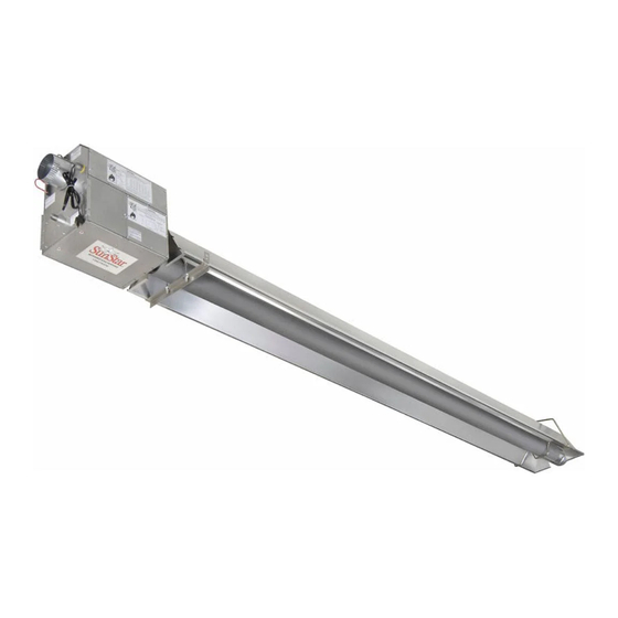
INFRARED RADIANT TUBE HEATER
Single Stage Push Through System (Positive Pressure)
SPS SERIES:
SPU SERIES:
!INSTALLER: This manual is the property of the owner. Please present this manual to the
owner when you leave the job site.
▲WARNING: Improper installation, adjustment, alteration, service, or maintenance can
cause property damage, injury or death. Read the installation, operation and maintenance
instructions thoroughly before installing or servicing this equipment.
IF YOU SMELL GAS:
! ! ! ! DO NOT
DO NOT
DO NOT
DO NOT try to light any appliance.
! ! ! ! DO NOT
DO NOT touch any electrical switch; DO NOT
DO NOT
DO NOT
telephone in your building.
! ! ! ! IMMEDIATELY
IMMEDIATELY call your gas supplier from a neighbor's
IMMEDIATELY
IMMEDIATELY
telephone. Follow the gas supplier's instructions. If you
cannot reach your gas supplier, call the fire department.
!IMPORTANT: SAVE THIS MANUAL FO
!IMPORTANT:
!IMPORTANT:
!IMPORTANT:
Post Office Box 36271 (28236) • 306 West Tremont Avenue (28203) • Charlotte, North Carolina
Phone (704) 372-3486 • Fax (704) 332-5843 • www.sunstarheaters.com • email: info@sunstarheaters.com
Models:
(40, 50, 75, 100, 125, 150, 175, 200) – N5/L5
(40, 50, 75, 100, 125, 150, 175, 200) – N5/L5
FOR YOUR SAFETY
FOR YOUR SAFETY
FOR YOUR SAFETY
FOR YOUR SAFETY
DO NOT use any
DO NOT
DO NOT
SAVE THIS MANUAL FOR FUTURE REFERENCE.
SAVE THIS MANUAL FO
SAVE THIS MANUAL FO
Manufactured for:
SUNSTAR HEATING PRODUCTS, INC.
SUNSTAR HEATING PRODUCTS, INC.
SUNSTAR HEATING PRODUCTS, INC.
SUNSTAR HEATING PRODUCTS, INC.
DO NOT store or use gasoline or other
DO NOT
DO NOT
DO NOT
store or use gasoline or other
store or use gasoline or other
store or use gasoline or other
flammable vapors and liquids in the vicinity of
flammable vapors and liquids in the vicinity of
flammable vapors and liquids in the vicinity of
flammable vapors and liquids in the vicinity of
this or any other appliance.
this or any other appliance.
this or any other appliance.
this or any other appliance.
R FUTURE REFERENCE.
R FUTURE REFERENCE.
R FUTURE REFERENCE.
Form 43343320
Aug 2012
Advertisement
Table of Contents

Subscribe to Our Youtube Channel
Related Manuals for SunStar SPS Series


Summary of Contents for SunStar SPS Series
-
Page 1: Installation And Operation Instructions
R FUTURE REFERENCE. R FUTURE REFERENCE. R FUTURE REFERENCE. Manufactured for: SUNSTAR HEATING PRODUCTS, INC. SUNSTAR HEATING PRODUCTS, INC. SUNSTAR HEATING PRODUCTS, INC. SUNSTAR HEATING PRODUCTS, INC. Post Office Box 36271 (28236) • 306 West Tremont Avenue (28203) • Charlotte, North Carolina Phone (704) 372-3486 •... -
Page 2: Table Of Contents
7.0) Typical Layouts – SPS/SPU Series ....................11 7.1) Typical Assembly Layout – (SPS SHOWN)..................12 8.0) Dimensions – SPS Series ........................ 13 8.1) Dimensions – SPU Series........................ 14 8.2) Heater Assembly / Joining of Tube Sections ................15 9.0) Typical Suspension Methods ...................... -
Page 3: Safety
1.0) SAFETY This heater is a self-contained infrared radiant tube heater. Safety information required during installation and operation of this heater is provided in this manual and the labels on the product. The installation, service and maintenance of this heater must be performed by a contractor qualified in the installation and service of gas fired heating equipment. - Page 4 Although these heaters may be used in many applications other than space heating (e.g., process heating), SunStar will not recognize the warranty for any use other than space heating. This heater is for Indoor Installation and Covered Patio Installation only and can be used in either Vented or Unvented mode.
-
Page 5: Minimum Clearances To Combustibles
NFPA54 requires that the installer must post signs that will “specify the maximum permissible stacking height to maintain the required clearances from the heater to combustibles.” to maintain the required clearances from the heater to combustibles.” SunStar SunStar recommends posting these recommends posting these to maintain the required clearances from the heater to combustibles.”... -
Page 6: Specifications
18 ft. 16 ft. * MOUNT HEATERS AS HIGH AS POSSIBLE. Minimums are shown as a guideline for human comfort and uniform energy distribution for complete building heating applications. Consult your SunStar representative for the particulars of your installation requirements. Type... - Page 7 BURNER PACKAGE NUMB BURNER PACKAGE NUMBERS BURNER PACKAGE NUMB BURNER PACKAGE NUMB NATURAL GAS NATURAL GAS NATURAL GAS NATURAL GAS PROPANE GAS PROPANE GAS PROPANE GAS PROPANE GAS MODEL MODEL MODEL MODEL NO. PART NO. PART NO. PART NO. PART NO. MODEL NO.
- Page 8 C. C. C. C. SPS SPS 40 40- - - - 200 Series Body Package Descriptions 200 Series Body Package Descriptions 200 Series Body Package Descriptions 200 Series Body Package Descriptions – – – – ALC Option (Aluminized Calorized) ALC Option (Aluminized Calorized) ALC Option (Aluminized Calorized) ALC Option (Aluminized Calorized) (Package Part Number is indicated on the outside of each corresponding carton.)
- Page 9 Body Fastener Kit (included in body packages) Body Fastener Kit (included in body packages) Body Fastener Kit (included in body packages) Body Fastener Kit (included in body packages) 42907190 42907190 42907190 42907190 42907210 42907210 42907210 42907210 42907210 42907210 42907210 42907221 42907210 42907221 42907221...
-
Page 10: Accessory Packages
End R End R eflector Accessory Package, Part #43341010 eflector Accessory Package, Part #43341010 (1 pkg. per SPS Series or 2 pkgs. per SPU Series) Contains: End Reflector, #43320000……QTY–2 Speed Clips, #02266010……QTY–8 B. B. B. B. Elbow Accessory Package, Part #43208010... - Page 11 C. C. C. C. Corner Reflector Accessory Package, Part #43342000 Corner Reflector Accessory Package, Part #43342000 Corner Reflector Accessory Package, Part #43342000 Corner Reflector Accessory Package, Part #43342000 (Option for SPS Series Only) Contains: Corner Reflector Assembly, #43345000……QTY–1 Speed Clips, #02266010……QTY–4 D.
-
Page 12: Typical Layouts - Sps/Spu Series
7.0) TYPICAL LAYOUTS – SPS/SPU SERIES LEGEND EMITTER LENGTH EMITTER LENGTH EMITTER LENGTH EMITTER LENGTH BODY LENGTH BODY LENGTH BODY LENGTH BODY LENGTH MODEL MODEL MODEL MODEL MODEL MODEL MODEL MODEL Min. Min. Min. Min. Max. Max. Max. Max. Min. Min. -
Page 13: Typical Assembly Layout - (Sps Shown)
7.1) TYPICAL ASSEMBLY LAYOUT – (SPS SHOWN) POISONOUS GAS AND SOOT HAZARD LEGEND Form 43343320 -12- Aug 2012... -
Page 14: Dimensions - Sps Series
8.0) DIMENSIONS – SPS SERIES Typical Dimensions Up to 60 Ft. Shown. Form 43343320 Aug 2012 -13-... -
Page 15: Dimensions - Spu Series
8.1) DIMENSIONS – SPU SERIES Typical Dimensions Up to 50 Ft. Shown. Form 43343320 -14- Aug 2012... -
Page 16: Heater Assembly / Joining Of Tube Sections
8.2) HEATER ASSEMBLY / JOINING OF TUBE SECTIONS Form 43343320 Aug 2012 -15-... - Page 17 Form 43343320 -16- Aug 2012...
-
Page 18: Typical Suspension Methods
6. Heaters must not be supported by gas or electric supply lines and must be suspended from a permanent structure with adequate load capacity. SunStar recommends that the body sections be suspended using chains with turnbuckles. This will allow slight adjustments after assembly and heater expansion/ contraction during operation. -
Page 19: Assembly Of Tube Sections
10.0) ASSEMBLY OF TUBE SECTIONS During field assembly of the heater body sections, the recommended procedure is as follows: 1. Before hanging heater sections, first determine the actual layout of the system (see Sections 7.0) & 8.0) for details). Consideration must also be taken for flue pipe, fresh air ducting, gas piping, clearances to combustibles, etc. -
Page 20: Assembly Of Extension Section
10.1) ASSEMBLY OF EXTENSION SECTION See typical assembly overview (Section 8.0)) for typical complete assembly. Assemble additional extension sections as required for all systems. (See Sections 7.0), and 8.0) for typical layout details.) Join the tube sections together and secure with tube couplings as described below: T T T T he following he following he following coupling... -
Page 21: Inserting Turbulators
4. Slide the next tube into the coupling. 5. Make sure both tube ends are butted together. 6. Finish tightening both bolts to 40-60 ft.lbs. torque to ensure a complete seal. 7. Use the two Self-drilling screws through the pre-punched holes to secure the tubes in the coupling. 8. -
Page 22: Adding Body Reflectors
MODEL MODEL 2 Ft. Turbulator Sections 2 Ft. Turbulator Sections MODEL MODEL 2 Ft. Turbulator Sections 2 Ft. Turbulator Sections SPS/U 40 SPS/U 50 SPS/U 75 SPS/U 100 SPS/U 125 SPS/U 150 SPS/U 175 SPS/U 200 10.3) ADDING BODY REFLECTORS 1. -
Page 23: Adding Optional 90º Elbow (Sps Only)
11.0) ADDING OPTIONAL 90º ELBOW (SPS ONLY) 1. The optional 90º elbow must be located a minimum of 10 ft. after the burner box. 2. Hang the body sections in a 90º ("L") shaped pattern. Allow spacing for the elbow. The distance from one end of the elbow to the centerline of the opposite leg is 13"... -
Page 24: Adding 180º U-Bend (Spu Only)
11.2) ADDING 180º U-BEND (SPU ONLY) 1. Hang body sections parallel with each other. The centerline distance from tube at each body section should be 18” as shown. 2. Join tube ends of body sections and the U-Bend together and secure with tube couplings as described in Section 10.1). -
Page 25: Attaching Burner Screen - (200M Btu Models Only)
12.0) ATTACHING BURNER SCREEN – (200M BTU MODELS ONLY) A burner screen is packaged with the control unit to prevent damage during shipment. This must be field installed as shown below before operation of the heater. 1. Remove cover panel 1. 2. -
Page 26: Attaching Burner Box Assembly
12.1) ATTACHING BURNER BOX ASSEMBLY 1. Attach the burner box and gasket to end of tube flange and secure with 1/4-20 locknuts. 2. Assemble the optional end reflector flush with the end of the main body reflector. Secure by sliding speed clips onto the reflector edges. -
Page 27: Connecting The Tiss System
12.2) CONNECTING THE TISS SYSTEM Desc Desc Desc Description: ription: ription: ription: The TISS TISS TISS TISS (Tube Integrity Safety System) (Tube Integrity Safety System) (Tube Integrity Safety System) is designed to shut the main burner off in the event that a (Tube Integrity Safety System) burnout occurs in the first 10ft. - Page 28 3. Hold the spring retainer clamp and pull the TISS TISS wire assembly to end of reflector at overlap joint. Slide TISS TISS spring retainer clamp over end of reflector as shown. Step 3 4. After attachment of the TISS TISS, check to make sure that there is sufficient tension on the wire.
- Page 29 ANGLE MOUNTED HEATERS ONLY ANGLE MOUNTED HEATERS ONLY ANGLE MOUNTED HEATERS ONLY ANGLE MOUNTED HEATERS ONLY 5. If heaters are to be angle mounted, the TISS wire holder clamp must first be re-positioned as shown using using using using the bottom hole pattern the bottom hole pattern of the clamp.
-
Page 30: Gas Connections And Regulations
13.0) GAS CONNECTIONS AND REGULATIONS IMPORTANT BEFORE CONNECTING THE GAS TO THE HEATER IMPORTANT BEFORE CONNECTING THE GAS TO THE HEATER IMPORTANT BEFORE CONNECTING THE GAS TO THE HEATER IMPORTANT BEFORE CONNECTING THE GAS TO THE HEATER 1. Connect to the supply tank or manifold in accordance with the latest edition of National Fuel Gas Code (ANSI Z223.1), and local building codes. - Page 31 RECOMMENDED GAS CONNECTION POSITIONS WITH 36” FLEXIBLE GAS HOSE INCORRECT POSITIONS WRONG WRONG WRONG WRONG US ONLY: US ONLY: Connector MUST be installed in “ Connector MUST be installed in “⊃ ⊃ ⊃ ⊃ ” configuration. Use only ” configuration. Use only US ONLY: US ONLY: Connector MUST be installed in “...
-
Page 32: Instructions For Pressure Test Gauge Connection
14.0) INSTRUCTIONS FOR PRESSURE TEST GAUGE CONNECTION DANGER SUPPLY PRESSURE SUPPLY PRESSURE SUPPLY PRESSURE SUPPLY PRESSURE 1. The installer will provide a 1/8” N.P.T. tapped plug, accessible for test gauge connection immediately upstream of the gas supply connection to the heater. MANIFOLD PRESSURE MANIFOLD PRESSURE MANIFOLD PRESSURE... -
Page 33: Electrical Connections
4. Check the burner at step pressure, observing burner ignition and flame characteristics. The burner should ignite properly and without flashback to the orifice, and should remain lit. GAS PRESSURE TABLE GAS PRESSURE TABLE GAS PRESSURE TABLE GAS PRESSURE TABLE SUPPLY PRESSURE SUPPLY PRESSURE SUPPLY PRESSURE... - Page 34 INTERNAL CONNECTION WIRING DIAGRAM INTERNAL CONNECTION WIRING DIAGRAM INTERNAL CONNECTION WIRING DIAGRAM INTERNAL CONNECTION WIRING DIAGRAM — — — — Direct Spark Ignition Direct Spark Ignition Direct Spark Ignition Direct Spark Ignition Tube Integrity Plaque à Safety Switch) bornes Schéma de circuit de connexion pressostat Robinet à...
- Page 35 FIELD CONNECTION FIELD CONNECTION FIELD CONNECTION FIELD CONNECTION AND THERMOSTAT AND THERMOSTAT AND THERMOSTAT WIRING DIAGRAMS AND THERMOSTAT WIRING DIAGRAMS WIRING DIAGRAMS WIRING DIAGRAMS A. A. A. A. LINE VOLTAGE (120V LINE VOLTAGE (120V LINE VOLTAGE (120V LINE VOLTAGE (120V) THERMOSTAT CONNECTIONS ) THERMOSTAT CONNECTIONS ) THERMOSTAT CONNECTIONS –...
-
Page 36: Venting
D. D. D. D. LOW VOLTAGE (24V) THERMOSTAT CONNECTIONS LOW VOLTAGE (24V) THERMOSTAT CONNECTIONS LOW VOLTAGE (24V) THERMOSTAT CONNECTIONS LOW VOLTAGE (24V) THERMOSTAT CONNECTIONS – – – – MULTIPLE HEATERS (utilizing a f MULTIPLE HEATERS (utilizing a f MULTIPLE HEATERS (utilizing a f MULTIPLE HEATERS (utilizing a fan center an center an center... - Page 37 SPS/U 175 SPS/U 175 SPS/U 175 SPS/U 200 SPS/U 200 SPS/U 200 Vent lengths shown in the table are for horizontal and vertical venting. If a longer length of vertical or horizontal venting is required contact the manufacturer for assistance with vent sizing. SINGLE HEATER VENTING SINGLE HEATER VENTING SINGLE HEATER VENTING...
- Page 38 3. Use the following correction factors to obtain the equivalent length when elbows are used: Subtract 10 ft. for each elbow beyond 15 ft. from the heater. • Subtract 15 ft. for each elbow within 15 ft. of the heater. •...
- Page 39 Multiple Heater Vertical Venting Arrangement Multiple Heater Horizontal Venting Arrangement VENT SIZING TABLE VENT SIZING TABLE VENT SIZING TABLE VENT SIZING TABLE — — — — Multiple Heate Multiple Heate Multiple Heate Multiple Heater Venting r Venting r Venting r Venting Number of Heaters Number of Heaters Number of Heaters...
-
Page 40: Air For Combustion
If the heater is installed less than 2 ft. from the ceiling, a combustion air inlet kit PN 44129510 must be provided to allow for expansion/contraction of straight tube heaters (SPS series). In colder climates, where necessary, insulate the outside combustion air duct. In high humidity applications, the burner box should be sealed with silicone sealer. - Page 41 In multiple heater applications multiple heater applications, the combustion air intake may be ducted individually or common ducted in the multiple heater applications multiple heater applications same configuration as shown for venting in Section 16.0). For combustion air intake duct sizing, please refer to the Vent Sizing Table Vent Sizing Table and use the diameter indicated, based on the number of heaters per duct.
-
Page 42: Lighting And Shutdown Instructions
18.0) LIGHTING AND SHUTDOWN INSTRUCTIONS DANGER 1. Turn on the gas and electrical supply. Rotate the gas valve knob counter-clockwise to the “ON” position. 2. Set the thermostat to call for heat. The blower motor will energize. 3. Ignition should occur after the 15-second pre-purge. 4. -
Page 43: Control Component Location
Note: When the SPS / SPU is operated by a thermostat interrupting the line voltage (120V) to the heater then the post purge function is disabled. If the flame is not sensed during sequence T3 then the burner will automatically begin re-ignition sequence T2. The ignition sequence will be repeated three times with a 60 second inter-purge. -
Page 44: Cleaning And Annual Maintenance
21.0) CLEANING AND ANNUAL MAINTENANCE ELECTRIC SHOCK & EXPLOSION HAZARD This heater must be cleaned and serviced annually by a qualified contractor before the start of each heating season and at any time excessive accumulation of dust and dirt is observed. Maximum heating efficiency and clean combustion will be maintained by keeping the heater clean. -
Page 45: Troubleshooting Guide
22.0) TROUBLESHOOTING GUIDE Form 43343320 -44- Aug 2012... - Page 46 Form 43343320 Aug 2012 -45-...
- Page 47 Form 43343320 -46- Aug 2012...
-
Page 48: Replacing Parts
23.0) REPLACING PARTS ELECTRIC SHOCK & EXPLOSION HAZARD Only use genuine SunStar replacement parts. Parts are available from the factory for replacement by a licensed person. Refer to the Replacement Parts Guide in Section 25.0) for all replacement parts. 23.1) REMOVAL OF MAIN BURNER AND ELECTRODES The main burner can be inspected without removing the burner housing from the heat exchanger tube. -
Page 49: Removing Gas Valve And Manifold Assembly
23.2) REMOVING GAS VALVE AND MANIFOLD ASSEMBLY 23.3) AIR SWITCH PRESSURE CHECK 0.65” WC Form 43343320 -48- Aug 2012... -
Page 50: Ignition System Checks
1. Open hinged access panel. 2. Add tubing to connect the air switch tubing P1 + and P2 - with the connector tees and the probes P1+ and P2+. 3. Connect plastic tubing of a digital or inclined water manometer with a 0-2” scale onto the connector tees. 4. -
Page 51: Installation Data
IGNITION MODULE DIAGNOSTICS IGNITION MODULE DIAGNOSTICS IGNITION MODULE DIAGNOSTICS IGNITION MODULE DIAGNOSTICS Flame Fault Flame Fault Flame Fault Flame Fault If at any time the main valve fails to close completely and maintains a flame, the full time flame sense circuit will detect it and energize the combustion blower. -
Page 52: Replacement Parts Guide
25.0) REPLACEMENT PARTS GUIDE BURNER BOX BURNER BOX BURNER BOX BURNER BOX Item No. Item No. Item No. Item No. Part No. Part No. Part No. Part No. Description Description Description Description Qty. Qty. Qty. Qty. Fasteners Fasteners Fasteners Fasteners 02295040 PHTCS #6-32 x 3/8"... - Page 53 Air Switch (set point @ .34”WC, GREEN LABEL) SPS/SPU125,150,175 & 200 Labels/Manual Labels/Manual Labels/Manual Labels/Manual 42848010 Label, Nameplate (SunStar) 42013010 Label, Logo (SunStar) (Not Shown) 43344060 Label, Clearances to Combustibles 42874020 Label, Wire Connection Diagram 42875000 Label, Warning (installation/configuration/chemical) 43269010...
- Page 54 Tube Integrity Plaque à Safety Switch) bornes Schéma de circuit de connexion pressostat Plaque à Robinet à gaz bornes Moteur Fusible d'amorce d'aspiration Transformateur bobine primaire 120ÊV bobine secondaire 24ÊV Haute tension Écartement d'électrode Bloc d'allumage 3,2Êmm Vers les autres radiateurs Circuit d'origine Lampes témoins...
- Page 55 ALL ILLUSTRATIONS ARE INTENDED TO GIVE THE GENERAL IMPRESSION OF UNITS ONLY. OTHER COMBINATIONS OF 5 FT. AND 10 FT. SECTIONS, AND ONES WITH OR WITHOUT THE ELBOW PACKAGE ARE POSSIBLE. PLEASE CONSULT WITH YOUR SUNSTAR SALES REPRESENTATIVE. WE RESERVE THE RIGHT TO ALTER ANY SPECIFICATION WITHOUT NOTICE. Form 43343320...
-
Page 56: Warnings Card
26.0) WARNINGS CARD Copies of this card may be ordered at no charge under part no. 43344980 for installation near the heater. Read the Installation and Operating Instructions thoroughly before installation, operation or service. WARNING FIRE HAZARD Maintain the following clearances: _____ to the side, _____ above and _____below the heater from combustible materials.
Need help?
Do you have a question about the SPS Series and is the answer not in the manual?
Questions and answers