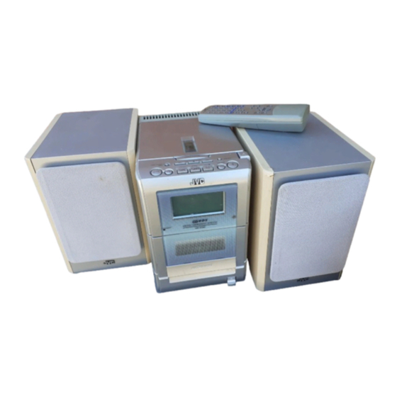
JVC UX-H35 Service Manual
Micro component system
Hide thumbs
Also See for UX-H35:
- Instructions manual (60 pages) ,
- Service manual (55 pages) ,
- Přiručka k obsluze (35 pages)
Advertisement
Quick Links
SERVICE MANUAL
MICRO COMPONENT SYSTEM
03
2003
22031
1
Important Safety Precautions . . . . . . . . . . . . . . . . . . . . . . . . . . . . . . . . . . . . . . . . . . . . . . . . . . . . . . . . . . . 1-2
2
Disassembly method . . . . . . . . . . . . . . . . . . . . . . . . . . . . . . . . . . . . . . . . . . . . . . . . . . . . . . . . . . . . . . . . . . 1-6
3
Adjustment. . . . . . . . . . . . . . . . . . . . . . . . . . . . . . . . . . . . . . . . . . . . . . . . . . . . . . . . . . . . . . . . . . . . . . . . . . 1-18
4
Description of major ICs . . . . . . . . . . . . . . . . . . . . . . . . . . . . . . . . . . . . . . . . . . . . . . . . . . . . . . . . . . . . . . . 1-24
UX-H35
TABLE OF CONTENTS
COPYRIGHT © 2003 VICTOR COMPANY OF JAPAN, LTD.
MICRO COMPONENT SYSTEM
Area Suffix
B -------------------------- U.K.
E ------- Continental Europe
EN --------- Northern Europe
UX-H35
No.22031
2003/03
Advertisement

Related Manuals for JVC UX-H35


Summary of Contents for JVC UX-H35
- Page 1 UX-H35 SERVICE MANUAL MICRO COMPONENT SYSTEM 22031 2003 UX-H35 MICRO COMPONENT SYSTEM Area Suffix B -------------------------- U.K. E ------- Continental Europe EN --------- Northern Europe TABLE OF CONTENTS Important Safety Precautions ............1-2 Disassembly method .
- Page 2 UX-H35 SECTION 1 Important Safety Precautions 1.1 Safety Precautions (1) This design of this product contains special hardware and exposed metal part and a known good earth ground. many circuits and components specially for safety purposes. Measure the AC voltage across the resistor with the AC For continued protection, no changes should be made to the voltmeter.
- Page 3 UX-H35 1.5 Safety Precautions (U.K only) (1) This design of this product contains special hardware and many circuits and components specially for safety purposes. For con- tinued protection, no changes should be made to the original design unless authorized in writing by the manufacturer. Replace- ment parts must be identical to those used in the original circuits.
- Page 4 UX-H35 1.6 Preventing static electricity Electrostatic discharge (ESD), which occurs when static electricity stored in the body, fabric, etc. is discharged, can destroy the laser diode in the traverse unit (optical pickup). Take care to prevent this when performing repairs.
- Page 5 UX-H35 1.9 Important for laser products (1) CLASS 1 LASER PRODUCT (5) CAUTION : If safety switches malfunction, the laser is able (2) DANGER : Invisible laser radiation when open and inter to function. lock failed or defeated. Avoid direct exposure to beam.
-
Page 6: Disassembly Method
UX-H35 SECTION 2 Disassembly method 2.1 Main body 2.1.1 Removing the rear panel (See Fig.1,2) (1) From behind the body, remove the eight screws A attach- ing the rear panel. (2) Turing the body upside down, remove the two screws B at- taching the rear panel, and remove. - Page 7 UX-H35 2.1.2 Removning the side panel (L) and (R) (See Fig.2~5) • Prior to performing the following procedure, remove the rear panel. (1) Turning the body upside down, remove the two screws C attaching the front panel assembly. (2) Turning the body initial position, open the CD door while pressing the upper OPEN button.
- Page 8 UX-H35 2.1.3 Removing the CD player assembly (See Fig.6,7) • Prior to performing the following procedure, remove the rear panel and the left and right side panels. CD player assembly CD servo control board (1) Disconnect the card wires from the two connectors CN603 CN604 and CN604 on the CD servo control board.
- Page 9 UX-H35 2.1.4 Removing the power amplifier board and heat sink (See Fig.8~10) • Prior to performing the following procedure, remove the rear panel, the left and right side panels, and the CD player assem- Power amplifier board bly. CN301 (1) Remove the five screws E and F attaching the heat sink.
- Page 10 UX-H35 2.1.5 Removing the tuner board (See Fig.11) • Prior to performing the following procedure, remove the rear panel, the left and right side panels, and the CD player assem- bly. (1) Remove the screw H attaching the tuner board from the right side of the body.
- Page 11 UX-H35 2.1.7 Remove the power transformer and power supply board (See Fig.14,15) • Prior to performing the following procedure, remove the rear panel, the left and right side panels, the CD player assembly, Jack holder the power amplifier board and the tuner board.
- Page 12 UX-H35 2.1.8 Remove the cassette mechanism assembly (See Fig.16,17) • Prior to performing the following procedure, remove the front panel assembly. Front panel assembly (1) Disconnect the card wire from the connector CN713 on the LCD system CPU board. (2) Remove the four screws K and L attaching the cassette mechanism assembly, and remove.
- Page 13 UX-H35 2.1.9 Remove the LCD system CPU board (See Fig.18) (1) Disconnect the wire from the connector CN716 on the LCD system CPU board. (2) Release the two joints f and pull out the LCD system CPU board. CN716 LCD system CPU board Fig.18...
- Page 14 UX-H35 2.2 Cassette mechanism assembly Cassette mechanism assembly Fly wheelR 2.2.1 Removing the Play/Record & Clear head (See Fig.1~3) (1) While moving the trigger arm on the right side of the head mount in the direction of the arrow, turn the flywheel R counterclockwise until the head mount comes ahead and clicks.
- Page 15 UX-H35 2.2.2 Removing the head amplifier & mechanism control board (See Fig.4) (1) Turn over the cassette mechanism assembly and remove the three screws A attaching the head amplifier & mecha- Head amplifier & mecha control board nism control board.
- Page 16 UX-H35 2.2.4 Removing the flywheel (See Fig.8, 9) • Prior to performing the following procedure, remove the head amplifier & mechanism control board and the main motor as- sembly. (1) From the front side of the cassette mechanism, remove the slit washers attaching the capstan shaft L and R.
- Page 17 UX-H35 2.2.6 Reattaching the Play/ Record & Clear head (See Fig.11~13) (1) Reattaching the head mount assembly. a) Change front of the direction cover of the head mount assembly to the left (Turn the head forward). b) Fit the bosses O', P', Q', U' and V' on the head mount assembly to the holes P and V, the slots O, U and Q of the mechanism sub assembly (See Fig.11 to 13).
- Page 18 UX-H35 SECTION 3 Adjustment 3.1 Adjustment method Measurement Instruments Required for Tuner section Adjustment FM tuning range: 87.5MHz~108.00MHz 1. Low frequency oscillator AM tuning range: 522kHz~1,629kHz This oscillator should have a capacity to output 0dBs to 600 at an oscillation frequency of Voltage applied to tuner +B : DC5.7V...
- Page 19 UX-H35 3.2 Cassette mechanism adjustment Head azinuth Head azinuth adjustment screw adjustment screw (Forward side) (Reverse side) CN31 Head azinuth Head azinuth R/P head, Erase head adjustment screw adjustment screw (Forward side) (Reverse side) Mecha control board VR37 R371 FW100...
- Page 20 UX-H35 3.2.1 Mechanism section Adjustment Item Condition Measurement method Ref.value position Only adjust Head Test tape 1.Playback the test tape VT703L (8kHz). Maximum at changed azimuth : VT703L (8kHz) 2.Adjust to maximum output level by azimuth output head Output terminal...
- Page 21 UX-H35 3.2.2 Electrical adjustment Adjustment Item Condition Measurement method Ref.value position VR31 AC-225 Recording 1.Set the test tape(AC-514 TYPE Forward or Reverse :4.20 A BIAS AC-225 TYPE ), then make REC/PAUSE Test tape AC-514 adjustment condition. :AC-514 TYPE :4.0 A 2.Connect 100...
- Page 22 UX-H35 3.3 Flow of functional operation until TOC read (CD) Check Point Slider turns REST Power ON Power Key Check that the voltage at the pin4 SW ON. of CN601 is 0V (a moment)? Automatic tuning of TE offset Check that the voltage at the...
- Page 23 UX-H35 3.4 Maintenance of laser pickup (CD) 3.5 Replacement of laser pickup (CD) (1) Cleaning the pick up lens Before you replace the pick up, please try to clean the lens Turn off the power switch and, disconnect the power cord from the ac outlet.
-
Page 24: Description Of Major Ics
UX-H35 SECTION 4 Description of major ICs 4.1 AN22000A-W (IC601) : RF & SERVO AMP • Terminal layout 9 10 11 12 13 14 15 16 • Block diagram 3TOUT NRFDET FEOUT TEOUT TEBPF VDET VREF 1-24 (No.22031) - Page 25 UX-H35 • Pin function Symbol I/O Function Symbol I/O Function - Ground I APC Amp. input terminal VREF O VREF output terminal O APC Amp. output terminal VDET O VDET output terminal - Power supply terminal TEBPF I VDET output terminal I RF adder Amp.
- Page 26 UX-H35 4.3 HA12238F (IC32) : R/P Equalizer • Pin layout TEST PB-NF1(L) (Open for nomal use) TEST 2 Iraf MUTE PBIN(l) ALC DET Return SW REC Return REC MUTE OFF/ON Return SW PBIN(R) MUTO ON/OFF REC RETURN ON/OFF MUTE TEST 3...
- Page 27 UX-H35 • Pin function Pin No. Symbol Function PB-NF2(R) PB EQ feed back PB-EQ(R) NAB output EQOUT(R) EQ output TAI(R) Tape input PBOUT(R) PB output NC pin REC IN(R) REC-EQ input ALC(R) ALC(R) signal out put NC pin REC OUT(R)
- Page 28 UX-H35 4.4 HA17758A (IC301) : Dual operational amp • Pin layout Vout1 Vin(-)1 Vout2 Vin(+)1 Vin(-)2 Vin(+)2 4.5 KIA78S05P-T (IC604) : Regulater • Pin layout • Block diagram 3 INPUT 1 OUTPUT 2 COMMON 1-28 (No.22031)
- Page 29 UX-H35 4.6 KIA78S06P-T (IC932) : Regulator • Pin layout 1 2 3 • Block diagram 3 INPUT 1 OUTPUT 2 COMMON (No.22031)1-29...
- Page 30 UX-H35 4.7 LA1838 (IC1): FM AM IF amp & Detector, FM MPX decoder • Block Diagram DECODER RF.AMP ANIT-BIRDIE MUTE BUFF STEREO P-DET AM IF PILOT 384KHz COMP S-METER AM/FM S-CLRVE S-METER IF-BUFF TUNING STEREO DRIVE DRIVE FM IF • Pin Function Pin No.
- Page 31 UX-H35 4.8 LA4663 (IC300) : 2ch power amp • Pin layout • Block diagram 2200 SIGNAL VCC1 VCC2 STAND BY MUTE CH 1 RL=4 to 8 +OUT1 Output Amp GND1 -OUT1 Input Amp OUTPUT-GND SHORT OUTPUT-VCC SHORT POLYESTER RL SHORT...
- Page 32 UX-H35 4.9 LA6541-X (IC801) : Servo driver • Pin layout & Block diagram Vref Vin4 Vin3 Level B T L B T L Level RESET shift driver driver shift Level B T L B T L Level Regulator shift driver...
- Page 33 UX-H35 4.10 LC72136N (IC2) : PLL frequency synthesizer • Pin layout FM/AM LPFOUT LPFIN CLOCK FM/ST/VCO FMIN AM/FM AMIN IFCONT SDIN IFIN • Block diagram Phase Reference Detector Driver Charge Pump Swallow Counter Swallow Counter 1/16,1/17 4bit 1/16,1/17 4bit Unlock...
- Page 34 UX-H35 4.11 LC72723(IC3): RDS demodulation • Pin layout VREF RDS-ID/READY MPXIN RDCL Vdda RDDA Vssa FLOUT MODE Vddd Vssd XOUT • Block Diagram VREF FLOUT Vdda CLOCK Vddd RECOVERY (1187.5Hz) REFERENCE (57kHz) VOLTAGE Vssa Vssd VREF 57kHz MPXIN (SCF) ANTI ALIASING...
- Page 35 UX-H35 4.12 LC75342 (IC302) : E. volume • Terminal layout • Block diagram LVref CONTROL CIRCUIT LOGIC CIRCUIT INTERFACE CONTROL RVref CIRCUIT • Pin function Pin No. Symbol Function Pin No. Symbol Function Serial data and clock input for IC control...
- Page 36 UX-H35 4.13 MN662748RPMFA (IC603) : Digital servo & Digital signal processer • Pin layout 80~61 21~40 • Pin function Pin No. Symbol I/O Function Pin No. Symbol I/O Function WVEL Not use BCLK Not use RF signal input LRCK Not use...
- Page 37 UX-H35 4.14 MN101C57CEW (IC931) : System micon • Pin layout 75 ~ 51 1 ~ 25 • Pin function Pin No. Symbol Description VLC1~VLC3 LCD BIAS VOLTAGE Not use REEL Tape End Detection _MPX FM Stereo Detection ('L'=STEREO) PERIOD Tuner PLL Strobe...
- Page 38 UX-H35 4.15 CD4094BC (IC33) : Serial to parallel port extension • Pin layout STROBE DATA OUTPUT ENABLE CLOCK • Block diagram DATA 8-STAGE SERIAL SHIFT REGISTER OUTPUT CLOCK 8-BIT STROBE LATHES 3-STATE OUTPUT OUTPUTS ENABLE PARALLEL OUTPUT 1-38 (No.22031)
- Page 39 UX-H35 (No.22031)1-39...
- Page 40 UX-H35 VICTOR COMPANY OF JAPAN, LIMITED AV & MULTIMEDIA COMPANY AUDIO/VIDEO SYSTEMS CATEGORY 10-1,1chome,Ohwatari-machi,Maebashi-city,371-8543,Japan (No.22031) Printed in Japan 200303WPC...
Need help?
Do you have a question about the UX-H35 and is the answer not in the manual?
Questions and answers