Viessmann Vitotronic 300 Installation And Service Instructions Manual
Outdoor-reset logic digital boiler and heating circuit control unit
Hide thumbs
Also See for Vitotronic 300:
- Installation and service instructions manual (164 pages) ,
- Operating instructions manual (73 pages) ,
- Technical data manual (9 pages)
Table of Contents
Advertisement
Quick Links
Installation and
Service Instructions
for use by heating contractor
Vitotronic 300, Model GW2
Outdoor-reset logic digital boiler and
heating circuit control unit
VITOTRONIC 300
Certified as a component part
of Viessmann boilers only
5285 941 v1.6 12/2012
IMPORTANT
Read and save these instructions
for future reference.
1
Advertisement
Chapters
Table of Contents

Subscribe to Our Youtube Channel
Related Manuals for Viessmann Vitotronic 300


Summary of Contents for Viessmann Vitotronic 300
- Page 1 Installation and Service Instructions for use by heating contractor Vitotronic 300, Model GW2 Outdoor-reset logic digital boiler and heating circuit control unit VITOTRONIC 300 IMPORTANT Read and save these instructions Certified as a component part for future reference. of Viessmann boilers only...
-
Page 2: General Information
General information Safety, Installation and Warranty Requirements Please ensure that this manual is read and understood before commencing installation. Failure to comply with the issues listed below and details printed in this manual can cause product/property damage, and/or severe personal injury. Ensure all requirements below are understood and fulfilled (including detailed information found in manual subsections). - Page 3 General information Product Information Vitotronic 300, Model GW2 For installation in or mounting on Applicable to the following control Viessmann boilers only. units Order No. 7134 555, 7143 156, 7511 362 from Serial No. 7143 000 Order No. 7134 555, 7143 156, 7511 362 from Serial No.
- Page 4 Index Page General information Safety Requirements ................Product information .
- Page 5 Index Page Scanning service information Overview of service levels ............. . . Temperatures, boiler coding cards and scanning .
- Page 6 Heating system types for modulating boilers System type 1 – Single-boiler system with shunt pump for raising the return temperature in conjunction with Vitorond 200, VD2 A1 M2 A Boiler with Vitotronic 300 plugs B Domestic hot water tank Outdoor temperature sensor DHW pump...
- Page 7 Heating system types Heating system types for modulating boilers (continued) When the return temperature falls Possible applications Temperature sensor T1 Heating systems with manifold below the required minimum value, Wiring of the temperature sensor arranged close to the boiler. The boiler the temperature sensor T2 switches T1 in heating systems with heating water flow is required to be reduced.
- Page 8 Heating system types Circuit Diagram 1 Single-boiler system with Therm-Control and three-way mixing valve in conjunction with Vitorond 200, VD2A A Heating circuit with mixing valves B DHW tank fÖ Power supply, 120 VAC Plug sÖM2 Outdoor temperature sensor Heating circuit pump, mixing 60 Hz Flow temperature sensor, valve...
- Page 9 Heating system types Circuit Diagram 1 (continued) Wiring diagram Wiring of the Therm-Control in heating systems with heating circuit control units are not connected to the boiler control unit via the LON. Required coding: Change “4C” to “2” - use the plug-in connector 20 A1 to close the downstream mixing valve.
- Page 10 (continued) System type 2 – Single-boiler system with shunt pump and return valve for raising the return temperature in conjunction with Vitorond 200, VD2 A Boiler with Vitotronic 300 plugs B Domestic hot water tank Outdoor temperature sensor DHW re-circulation pump...
- Page 11 Heating system types Heating system types for modulating boilers (continued) When the return temperature falls Possible applications Heating systems with distributor below the required minimum value, arranged close to the boiler. The boiler the temperature sensor T2 switches water flow is required to be reduced. on the shunt pump.
- Page 12 Heating system types Heating system types for condensing boilers System type 3 – Single-boiler system with Vitocrossal 300 A Boiler with Vitotronic 300 plugs B Domestic hot water tank Outdoor temperature sensor Circulation pump for heating C Heating circuit with mixing valve...
- Page 13 This circuit diagram represents a by means of the outdoor re-set boiler recommendation only. It is the control unit. Viessmann modulating responsibility of the customer and/or burner is operated through Vitotronic the heating contractor to check that control.
- Page 14 Heating system types for condensing boilers (continued) System type 4 - Single-boiler system with Vitocrossal 300 with several heating circuits and one modulating supply temperature heating circuit A Boiler with Vitotronic 300 plugs B Domestic hot water tank Outdoor temperature sensor...
- Page 15 Heating system types Heating system types for condensing boilers (continued) The Vitocrossal 300 is operated with Possible applications Pumps in the underfloor heating For heating circuits with different modulating boiler water temperature circuit temperatures. by means of the outdoor re-set boiler control unit.
- Page 16 Heating system types Heating system types for condensing boilers System type 5 – Single-boiler system with Vitocrossal 200 A Boiler with Vitotronic 300 plugs B Domestic hot water tank Outdoor temperature sensor Circulation pump for heating C Heating circuit with mixing valve...
- Page 17 This circuit diagram represents a by means of the outdoor re-set boiler recommendation only. It is the control unit. Viessmann modulating responsibility of the customer and/or burner is operated through Vitotronic the heating contractor to check that control.
- Page 18 Installation Overview of electrical connections Mixing valve extension circuit board Low-voltage motherboard Line voltage motherboard ? M2/M3 Supply temperature sensor sÖ A1 Heating circuit pump or Outdoor temperature sensor sÖ M2/M3 Heating circuit pump (ATS) control output gS M2/M3 Mixing valve motor §...
- Page 19 Installation Overview of electrical connections(for VD2/VD2A/CT3 only)
- Page 20 Installation Overview of electrical connections (for CM2 only)
- Page 21 Installation Routing and strain relief of cables 1. Run the cables from the connection enclosure into the control unit. 2. Apply strain relief to cables (see below). Cables with moulded strain relief clamp Connect cable and strain relief clamp. Fasten cable to the cable lead with cable tie.
- Page 22 Installation Inserting the boiler coding card CAUTION For matching the operation of the control unit to the boiler, only the boiler coding card which is supplied as part of the standard delivery of the boiler may be used. Only use the boiler coding card included with the boiler. Boiler Coding card Part No.
- Page 23 Installation Adjustment of the fixed high limit (if required) The fixed high limit is supplied with a factory setting of 110°C / 230°F. Adjustment to 99°C / 210°F ¨ Disconnect power to control and burner! 1. Unclip the fuse box and swing upwards.
- Page 24 Installation Adjustment of the adjustable high limit (if required) The adjustable high limit is supplied with a factory setting of 95°C. Adjustment to 100°C / 212°F 1. Using a suitable screwdriver, lever out and remove the selector knob ”R” behind the hinged cover.
- Page 25 Installation Connection of the outdoor temperature sensor The outdoor temperature sensor should be mounted 2 to 2.5 metres / 6.5 to 8 ft above ground level on the north or north-west facing wall of the building. In the case of multi-storey buildings, it should be mounted in the upper half of the second storey.
- Page 26 Installation Connection of the boiler temperature sensor The sensor measures the boiler water temperature. The boiler temperature sensor is installed at the same time as the boiler insulation. Check the sensor 1. Disconnect plug § in the terminal compartment of the boiler control.
- Page 27 Installation Connection of the DHW tank temperature sensor The sensor measures the domestic hot Heating systems with domestic hot Check the sensor 1. Disconnect plug % in the water tank temperature. water heating (single-boiler systems terminal compartment of the only) boiler control.
- Page 28 Installation Connection of the return temperature sensor Strap-on temperature sensor and immersion temperature sensor For measuring the boiler return temperature. Electrical connection The sensor is inserted in socket ”17A” or ”17B” on the boiler control. 17A or 17B Check the sensor 1.
- Page 29 Installation Connection of the flue gas temperature sensor (VD2/VD2A/CT3 only) The sensor measures the flue gas temperature and monitors the selected limit value. Electrical connection The sensor is inserted in socket ”15” on the boiler control. Check flue gas temperature sensor 1.
- Page 30 Installation Connection of the Pumps (VD2/VD2A/CT3 only) Available pump connections sÖ A1/M1Heating circuit high 120 VAC pumps 240 VAC or 3 PH pumps temperature (without mixing valve) Terminals 5 - L, - G , - N Note: Please note: The maximum power consumption of Use contactor and/or motor starter to Circulation pump for heating all pumps is 4A .
- Page 31 Installation Connection of the Pumps (CM2 only) Available pump connections sÖ A1/M1Heating circuit high 120 VAC pumps 240 VAC or 3 PH pumps temperature (without mixing valve) Terminals 7 - L, - G , - N Note: Please note: The maximum power consumption of Use contactor and/or motor starter to Circulation pump for heating all pumps is 4A .
- Page 32 Installation Connection of boiler return mixing valve or modulating valve actuator (VD2/VD2A/CT3 only) 1 120V or 24V valve adaptor 1 120V valve adaptor 1 24V valve adaptor 2 DIN rail in connection enclosure 2 120V valve actuator 2 24V valve actuator 3 aBH Terminals 1.
- Page 33 Installation Connection of Boiler Return Mixing Valve or Isolation/Modulating Valve actuator (CM2 only) 10 11 12 1 120V or 24V Valve Adaptor 1 120V Valve Adaptor 1 24V Valve Adaptor 2 Junction box 2 120V valve actuator 2 24V valve actuator 3 120V L out power supply 1.
- Page 34 Installation Making Space for Accessory Adaptors on the DIN Rail (CM2 only) 1. Push up on the bottom front of the DIN rail clamp to remove and set aside. 2. Using a flat head screwdriver, remove the 4 ’spare’ DIN terminals 23, 24, 25 and 26 one at a time.
- Page 35 Installation Connections to terminal aBÖ (VD2/VD2A/CT3 only) External shut-off 1. Remove jumper between terminals 16 and 17. 2. Connect dry contact. Controlled switch-off takes place when the contact is opened. WARNING The terminals should be used for safety switch-off purposes only (e.g.
- Page 36 Installation Connection of the compiled failure alarm indicator (VD2/VD2A/CT3 only) Rated voltage: 120 VAC 60 Hz Rated current: max. 2 FLA Recommended connection wire size: AWG 14 1. Disconnect power to control and burner. 2. Connect the compiled failure alarm as shown in the diagram. A Connect terminal strip in connection enclosure of boiler control.
- Page 37 Installation Connection of the compiled failure alarm indicator (CM2 only) Rated voltage: 120 VAC 60 Hz Rated current: max. 2 FLA Recommended connection wire size: AWG 14 1. Disconnect power to control and burner. 2. Connect the compiled failure alarm as shown in the diagram. A Connect terminal strip in connection enclosure of boiler control.
- Page 38 Installation Connection of external equipment to terminal aVD External changeover of the heating program/”Open mixing valves” Connect floating contact to terminals ”1” and ”2”. The manually preselected heating program can be changed over (see table) and the mixing valves opened via the contact.
- Page 39 Installation Connection of external equipment to plug aVH External demand Connect floating contact to terminals ”2” and ”3”. The burner of the boiler is switched in on a load-dependent basis when the floating contact is closed. The boiler water temperature is limited by the preset max.
- Page 40 Installation Connection of external controls Operation with two-stage burner Settings on the control unit The settings for the fixed high limit and the other settings are dependent on the safety equipment installed in accordance with applicable codes. Non-condensing boiler Condensing boiler Condensing boiler (VD2/VD2A) °C / °F (CT3) °C / °F...
- Page 41 Installation Connection of external controls (VD2/VD2A only) (continued) Modulating boilers – operation with external modulation controller 1st stage burner fA from Vitotronic. Boiler activation, isolation valve open or closed Plug lÖ from Vitotronic via Connect dry contact at terminals ”2” and ”3” of the plug aVH. modulation controller (BAS).
- Page 42 Installation Connection of external controls (VD2/VD2A only) (continued) Modulating boilers – operation with external modulation controller (continued) Settings on the control unit The settings for the fixed high limit and the other settings are dependent on the safety equipment installed in accordance with applicable codes.
- Page 43 Installation Connection of external controls (CT3 only) (continued) Vitocrossal 300 – operation with external modulation controller 1st stage burner fA from Boiler activation, isolation valve Vitotronic 100. open or closed Connect dry contact at terminals Connection lÖ from Vitotronic has ”2”...
- Page 44 Installation Connection of external controls (CT3 only) (continued) Vitocrossal 300 – operation with external modulation controller (continued) Settings on the control unit The settings for the fixed high limit and the other settings are dependent on the safety equipment installed in accordance with applicable codes.
- Page 45 Installation Connections of combustion air device adaptor (VD2/VD2A/CT3 only) Connection of the Combustion Air Device Adaptor 1. Disconnect power to control and burners. 2. Install Combustion Air Device Adaptor, Part No.: 7134 563 on DIN Rail inside connection enclosure (refer to installation manual of Combustion Air Device Adaptor).
- Page 46 Installation Connection of Combustion Air Device (CM2 only) Connection of the Combustion Air Connection of the combustion air Device Adaptor blower to adaptor 1. Disconnect power to control and Rated voltage: 120 VAC burners. Rating current: max 5 FLA Recommended connection 2.
- Page 47 Installation Connection of combustion air device (continued) Connection of the combustion air damper See damper manual for correct installation. Note: Assure that the combustion air damper is suitable for this application. 1. Disconnect power to control and burner. 2. Make connection as shown in the diagram.
- Page 48 Installation Flue Gas Temp. Switch (mandatory for PP(s) material collectors) (CM2 only) 1. Disconnect power. CAUTION 2. Remove 150 plug from the Please note that the diagram shown Vitotronic control and discard. is only a simplified conceptual drawing of a flue gas temperature 3.
- Page 49 Installation Connection of low water cut-off device (VD2/VD2A/CT3 only) 1.Remove jumper between terminals 12 and 15. 2.Make connection as shown in diagram. CAUTION Please note that the diagram at left is only a simplified conceptual drawing of a typical low water cut off (LWCO) device.
- Page 50 Installation Connection of Low Water Cut-off Device (CM2 only) 1. Remove jumper between terminals 21 and 22. 2. Make connection as shown in diagram. CAUTION Please note that the diagram shown is only a simplified conceptual drawing of a typical low water cut-off (LWCO) device.
- Page 51 Installation Burner connection, Burner control wiring (VD2/VD2A/CT3 only) For burners with plug-in connection The burner cables are included in the standard delivery of the Vitotronic. Connect the burner in accordance with applicable codes. 1.Disconnect power to burner and ATo boiler control unit boiler control.
- Page 52 Burner, 2nd stage b External controlled switch-off D Burner fault indicator * (remove jumper when connecting) E Control circuit, stage 1/ aBA Safety circuit. Emergency basic load * shut-off F Burner Refer to burner manufacturer’s instruction on detailed connections for Viessmann controls.
- Page 53 (continued) See burner manual for correct fuse and wire gauge sizing, and specific For burners with 240 VAC, 1PH power connections for Viessmann controls. supply and connection in conduit. 1.Disconnect power to burner and boiler control. 2.Connect 240 VAC power to the...
- Page 54 (continued) Burner motor power supply connection See burner manual for correct fuse (continued) and wire gauge sizing, and specific connections for Viessmann controls. For burners with 3PH 208, 460 or 575V power supply. 1.Disconnect power to burner and boiler control.
- Page 55 Installation Power Supply Connection, Boiler Control (VD2/VD2A/CT3 only) 1. Ensure that the main power supply Legend L: Line to the control contains overcurrent N: Neutral protection with a maximum rating G: Ground of 15 A and 2 pole disconnect. A Power supply 120 VAC, 1 PH . Provide disconnect means and CAUTION overcurrent protection as per local...
- Page 56 Installation Burner Connection, Burner Control Wiring (CM2 only) For burners with plug-in connection The burner cables are included in the standard delivery of the Vitotronic. Connect the burner in accordance with applicable codes. ATo boiler control unit 1.Disconnect power to burner and BTo burner interface boiler control.
- Page 57 Installation Mounting the Front Part of the Control Unit (VD2/VD2A/CT3 only) 1. Position the front part of the housing and clip hinges to counter-parts on main housing. 2. Release the stay bar, open it up and lock in position at point A. 3.
- Page 58 Installation Mounting the Front Part of the Control Unit (VD2/VD2A/CT3 only) 1. Position the front part of the housing and clip hinges to counter-parts on main housing. 2. Release the stay bar, open it up and lock in position at point A. 3.
- Page 59 Installation Opening the Control Unit (VD2/VD2A/CT3 only) 1. Remove the cover of the connection enclosure. 2. Unscrew the screws from the front housing. 3. Swing up the front part of the control housing. 4. Position the stay bar so that it supports the front housing.
- Page 60 Installation Control and Junction Box Installation Instructions (for CM2 only) 1. Route cables and capillaries from control through the opening in the control panel. Guide the cables to the junction box through the opening in the rear panel and along the top rail to the control.
- Page 61 Installation Mounting the Front Part of the Control Unit (CM2 only) 1. Position the front part of the housing and clip hinges to counter-parts on main housing. 2. Release the stay bar, open it up and lock in position at point A. 3.
- Page 62 Installation Opening the Control Unit (CM2 only) 1. Remove the control cosmetic cover . 2. Unscrew the screws from the front housing. 3. Swing up the front part of the control housing. 4. Position the stay bar so that it supports the front housing.
-
Page 63: Table Of Contents
Start-up Procedure (overview) Page 11. Controls and indicators ................12. -
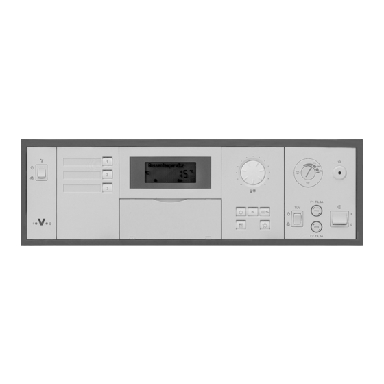
Page 64: Controls And Indicators
Start-up Steps 1. Controls and indicators Override switch Heating circuit selection Display window Normal room temperature Heating programs Adjustable high limit Kesseltemperatur Fixed high limit reset button Control on/off switch Fuses TÜV TEST button Energy saving mode Party mode Hinged cover of programming unit Operating status indicator (green) Fault indicator (red) 2. -
Page 65: Check The Fixed High Limit
Start-up Steps (continued) 3. Check the fixed high limit The check is made via the ”TÜV TEST” button (see page 64). When making the check, the ” TÜV TEST” button must be kept continuously pressed. A minimum supply is required during the check. -
Page 66: Integrate The Control Unit In The Lon Bus System (In Conjunction With Heating Circuits Connected Downstream)
2. Press D. after approx. 2 minutes. The participant check is terminated. Example of single-boiler system with Vitotronic 200-H heating circuit controls and Vitocom 300 connected downstream Vitotronic 300 Vitotronic 200-H Vitotronic 200-H Vitocom Participant No. 1 Participant No. 10 Participant No. -
Page 67: Carry Out Participant Check
Start-up Steps (continued) 6. Carry out participant check The participant check is used to verify the communication of the system units connected to the fault manager. Requirements: The control unit must be coded as the fault manager (coding ”79: 1”) The LON participant number must be coded in all control units The participant list must be updated in the fault manager 1. -
Page 68: Match The Control Unit To The System Type
Start-up Steps (continued) 7. Match the control unit to the system type Set the following coding addresses in See page 116 for coding 2. Coding 2: ”00” System type ”02” Burner type ”03” Oil or gas-fired operation ”0C” Return temperature raising ”4C”... -
Page 69: Match The Coding Addresses
Start-up Steps (continued) Check sensors 1. Press Scanning of operating status Relaistest information is activated 2. Scan actual temperatures with (see page 77). 3. Press Scanning is terminated. 9. Match the coding addresses Match control unit to modulating burner Please note: The burner must be adjusted. - Page 70 Start-up Steps (continued) 9. Match the coding addresses (continued) 10. Set the established values in coding See page 114 for coding 1. Level 1. Address Setting of the partial output (see point 8) as a percentage proportion of the max. output; e.g. partial output: 170 kW max.
-
Page 71: Adjust The Heating Curves
Start-up Steps (continued) 10. Adjust the heating curves The heating curves represent the relationship between the outdoor temperature and the boiler water or supply temperature. Put simply: The lower the outdoor temperature, the higher the boiler water temperature. In turn, the room temperature is dependent on the boiler water temperature. - Page 72 Scanning service information Overview of service levels Function Button combination To exit Page Temperatures, boiler coding cards Press 9 and rw simultaneously Press “OK” and scans for approx. 2 seconds Relay test Press 9 and “OK” simultaneously Press “OK” for approx. 2 seconds Participant check (in conjunction Press w and “OK”...
- Page 73 Scanning service information Temperatures, boiler coding cards and scans 1. Press 9 and rw simultaneously Access diagnosis level. Outdoor temp. damped for approx. 2 seconds. 2. Select the required data for scanning with the button. 3. Press Exit diagnosis level. The following values can be scanned depending on the system equipment installed:...
- Page 74 Scanning service information Temperatures, boiler coding cards and scans (continued) Scan 1 Scan 1 Free Free KM BUS participant No participant connected Number of participants (e.g. remote control) Burner type Coding Single-stage 02: 0 2-stage 02: 1 Modulating 02: 2 System type System circuit A1 Mixing valve Mixing valve...
- Page 75 Scanning service information Temperatures, boiler coding cards and scans (continued) Scan 2 Scan 2 Software version Plug-in adaptor for external safety equipment Software version Extension kit for mixing valve circuit M3 Free Software version Extension kit for mixing valve circuit M2 Software version Programming unit of control unit Software version...
- Page 76 Scan 4 is not assigned. Scan 5 only in conjunction with LON communication module Scan 5 Node address Subnet address/system number Viessmann participant number Scan 6 only in conjunction with LON communication module Scan 6 LON participant No participant connected...
- Page 77 Scanning service information Scanning operating status information 1. Press Operating status scanning mode Outdoor temperature is activated. 2. Select the required operating status data for scanning with the button. 3. Press Exit the operating status scanning mode. The following operating status information can be scanned depending on the system equipment installed: Participant number...
- Page 78 Scanning service information Scanning and resetting the ”Service” display When the limit values selected via coding addresses ”1F”, ”21” and ”23” (see page 120) are reached, the ”Service” display flashes on the programming unit. Please note: If a service is carried out before ”Service” is displayed, set the coding address ”24: 1”...
-
Page 79: Troubleshooting
Troubleshooting Troubleshooting steps Diagnosis 1. Establish fault message or ascertain behaviour of system 2. Look for the corresponding cause of the fault in the diagnosis tables Please note: Retrieve fault codes from the fault memory 3. Establish the action required in the table Correction 4. -
Page 80: Outdoor Sensor
Troubleshooting Diagnosis Faults with fault display on the programming unit Fault Fault The meaning of the fault code is When a fault message is transmitted, --Fault-- flashes in the display 1 of the explained in the table on page 81 ºC onwards. - Page 81 Troubleshooting Diagnosis (continued) Faults with fault display on the programming unit (continued) Fault code Cause of fault Action Behaviour of system in display Controlled operation Service required Carry out maintenance ”0F” is only displayed Please note: in the fault history After carrying out main- tenance, set coding ”24: 0”.
- Page 82 Troubleshooting Diagnosis (continued) Faults with fault display on the programming unit (continued) Fault code Cause of fault Action Behaviour of system in display Boiler with maximum temperature Short circuit Check temperature sensor Temperature sensor aJA No output reduction (see page 102) Return control open Boiler with maximum temperature Open circuit...
- Page 83 Troubleshooting Diagnosis (continued) Faults with fault display on the programming unit (continued) Fault code Cause of fault Action Behaviour of system in display Insert plug aJA Controlled operation Therm-Control configuration fault: plug aJA of On Vitocrossal: Therm-Control temperature Check that coding ”0d: 0” sensor not inserted is set.
- Page 84 Troubleshooting Diagnosis (continued) Faults with fault display on the programming unit (continued) Fault code Cause of fault Action Behaviour of system in display Boiler cools down External safety equipment Check connection of plug aBÖ Check external safety equipment (see page 40) Controlled operation Open circuit Check KM-BUS connection and...
- Page 85 Troubleshooting Diagnosis (continued) Faults with fault display on the programming unit (continued) Fault code Cause of fault Action Behaviour of system in display Controlled operation without Short circuit Check room temperature sensor influence of room temperature Room temperature sensor, (see page 112) mixing valve circuit M3 Controlled operation without Open circuit...
- Page 86 Functional description Boiler temperature control Brief description The boiler water temperature is When the domestic hot water tank Coding addresses which influence controlled by switching the burner is heated up, a desired boiler water the boiler temperature control stages or modulation on and off. temperature is selected which is The desired boiler water temperature 20°C / 36°F higher than the desired...
- Page 87 Functional description Heating circuit control Brief description The control unit has control loops for a The supply temperature of the mixing The supply temperature of the system system circuit and two mixing valve valve circuits is controlled by opening circuit corresponds to the boiler water circuits.
- Page 88 Functional description Heating circuit control (continued) Functions (continued) Summer energy saving function System dynamics – mixing valve Supply temperature control circuit (only in conjunction with (heating circuit pump logic) mixing valve circuit) Differential temperature: If the outdoor temperature is higher The differential temperature can be than the preset room temperature The control behaviour of the mixing...
- Page 89 Functional description Heating circuit control (continued) Functions (continued) Upper limit of control range Lower limit of control range Electronic maximum limit Electronic minimum limit Setting range: Setting range: 1 to 127°C / 34 to 260°F. 1 to 127°C / 34 to 261°F. Change via coding address ”C6”.
- Page 90 Functional description DHW tank temperature control Brief description The DHW tank temperature control is a During DHW tank heating, a constant Coding addresses which influence constant value control. It operates on maximum boiler water temperature is the DHW tank temperature control the basis of switching the circulation set and space heating is switched off pump for heating the DHW tank on and...
- Page 91 Functional description DHW tank temperature control (continued) Control sequence DHW tank temperature falls DHW tank temperature rises (Set-point value –2.5 °C / 4.5 °F, (Set-point value +2.5 / 4.5°F) selectable via coding address ”59”) The boiler water temperature set-point The desired boiler water temperature value is reset to the weather- is set 20 K higher than the DHW compensated value.
- Page 92 Additional information Overview Page Technical data ................................. . System components Line-voltage motherboard .
-
Page 93: Technical Data
Additional information Technical data Rated voltage: 120V Ambient temperature Relay outputs at 120V for Rated frequency: 60 Hz Heating circuit Rated current: 2 x 6A During pumps or control output sÖ: Power operation: 0 to 40°C / 2 FLA, 120 VAC consumption: 32 to 104°F Circulation... -
Page 94: System Components
Additional information System components Line voltage motherboard, Part No. 7165 782 The motherboard contains: Relays and outputs for activating the pumps, the control elements and the burner Plug-in location for power supply unit board and boiler control section Low-voltage motherboard, Part No. 7820 290 The motherboard contains: Plugs for sensors, communication connections and external... -
Page 95: Optolink/Emissions Test Switch Board
Additional information System components (continued) Mixing valve extension board, Part No. 7820 193 The board contains the relays for activating the mixing valve motor and the heating circuit pump of the mixing valve circuits M2 and M3. Electronics board, Part No. 7829 790 This is connected to the mixing valve extension board. -
Page 96: Fuses
Additional information System components (continued) Front panel with heating circuit selector buttons, Part No. 7818 623 For displaying and selecting the heating circuit. Fuse box, Part No. 7820 172 The fuse box contains: Fixed high limit Adjustable high limit Fuses Heating system switch TEST button LON communication module, Part No. - Page 97 Additional information System components (continued) Boiler coding card Vitotronic 300 Boiler coding card Part No. in conjunction with Vitorond 200 1020 7820 142 Vitocrossal 300, Type CT3 1040 7820 144 Vitocrossal 200, Type CM2 1041 7820 145 Fuses F1: 6.3 A, 250 V for protecting...
- Page 98 Additional information System components (continued) Fixed high limit, Part No. 7820 036 The fixed high limit has a factory setting of 110°C/ 230°F. Electromechanical temperature switch based on the liquid expansion principle with interlock Intrinsically safe; interlocking also takes place if the capillary tube is leaking or if ambient temperatures are below –10°C / 14°F Limits the boiler water temperature to the maximum permissible value by cutting out and interlocking...
-
Page 99: Outdoor Temperature Sensor
Additional information System components (continued) Outdoor temperature sensor, Part No. 7820 148 Outdoor temperature sensor Connection Check sensor 1. Remove plug !. 2. Check the sensor resistance at terminals 1 and 2 of the plug. Outdoor Resistance temperature in in Ω Ω Ω Ω ºC / ºF –10 / 14 0 / 32... - Page 100 Additional information System components (continued) Outdoor temperature sensor The outdoor temperature sensor should be mounted 2 to 2.5 metres / 6.5 to 8 ft above ground level on the north or north-west facing wall of the building. In the case of multi-storey buildings, it should be mounted in the upper half of the second storey.
- Page 101 Additional information System components (continued) Boiler temperature sensor, Part No. 7450 632 and DHW tank temperature sensor, Part No. 7450 633 Electrical connection See page 38. Check the sensor 1. Disconnect plug § / % in the terminal compartment. 2. Measure resistance of sensor at terminals ”1”...
-
Page 102: Strap-On Temperature Sensor/Immersion Temperature Sensor
Additional information System components (continued) Strap-on temperature sensor and immersion temperature sensor For measuring the supply temperature. Electrical connection The sensor is inserted in socket ? on the control unit. Check the sensor 1. Disconnect plug ? in the terminal compartment. 2. - Page 103 Additional information System components (continued) Strap-on temperature sensor and immersion temperature sensor For measuring the return temperature. Electrical connection The sensor is inserted in socket ”17A” or ”17B” on the control unit. 17A or 17B Check the sensor 1. Disconnect plug aJA or aJB in the terminal compartment.
-
Page 104: Flue Gas Temperature Sensor
Additional information System components (VD2/VD2A/CT3 only) (continued) Flue gas temperature sensor, Part No. 7450 630 Accessory See page 48 for CM2 flue gas The sensor measures the flue gas temperature switch. temperature and monitors the selected limit value. Electrical connection The sensor is inserted in socket ”15”... -
Page 105: Installation Examples
Additional information System components (continued) Installation examples In the as delivered condition, the electrical connections of The electrical connections of the mixing valve motor must the mixing valve motor are as required for the following be changed for the following installation examples. installation examples;... -
Page 106: Vitotrol 200
Additional information System components (continued) Vitotrol 200 , Part No.7133 378 (with integral room temperature sensor for room temperature feed-back in conjunction with a mixing valve circuit) Setting of: Day temperature Heating program Economy and party mode Function changes can be made via coding addresses A0, b0 to b9, C0 to C2, E1 and E2 (see coding overview). Connection 2-wire cable 50m / 164 ft Room temperature sensor connection... -
Page 107: Remote Control
Additional information System components (continued) Remote control (continued) Specification Power supply via 145 KM BUS. Safety class: Protection: IP 30 Permiss. ambient temperature During operation: 0 to +40°C 32 to + 104°F In storage and transport: 1 2 3 4 –20 to +65°C –4 to +149°C Set room temperature... - Page 108 Additional information System components (continued) Vitotrol 300 , Part No. 7134 452 (with integral room temperature sensor for room temperature feed-back in conjunction with a mixing valve circuit) Setting of: Normal and reduced temperature Domestic hot water temperature Heating program Holiday program Switching times Economy and party mode...
- Page 109 Additional information System components (continued) Remote control (continued) Specification Power supply via 145 KM BUS. Safety class: Protection: IP 30 Permiss. ambient temperature In use: 0 to +40°C 32 to 104°F In storage and transport: D Printed Circuit Board DIP switches –20 to +65°C (rear of the top casing) –4 to +149°F...
- Page 110 Additional information System components (continued) Connecting several remote control units When connecting several remote controls to the control unit, install a terminal box on site. Version 1 max. max. max. 15 m / 50 ft 15 m / 50 ft 15 m / 50 ft A To control unit On-site connection via terminal box:...
- Page 111 Additional information System components (continued) Version 2 max. 15 m / 50 ft max. 15 m / 50 ft max. 15 m / 50 ft A To control unit If several remote control units and B Terminal box (on site) additional KM BUS participants are C Vitotrol 1 connected, make the connections via...
- Page 112 Additional information System components (continued) Room temperature sensor, Part No. 7133 379 Accessory The room temperature sensor serves to measure the room temperature where the remote control cannot be located in a suitable position. Technical data Degree of protection: IP 30 Ambient temperature During operation:...
-
Page 113: Input Module 0 To 10V
Additional information System components (continued) Input Module 0 to 10 V, Part No. 7134 561 From software version 7, the Input Module can be connected (software version via scan 2: 1st digit, display ≥7). For external control of the boiler/supply temperature via a 0 to 10VDC signal 10 to 100°C or 30 to 120°C (50 to 212°F or 86 to 248°F) to signal reduced mode and regulate a heating circuit pump to a lower speed. -
Page 114: Coding 1
Additional information Coding 1 Call up coding level 1 Only those coding addresses are displayed which correspond to the system type and equipment concerned and can be changed accordingly. 1. Press 9 and w simultaneously for Access coding level 1. Coding 1 approx. -
Page 115: Coding 1
Additional information Coding 1 (continued) Codings (continued) Function Coding as per factory setting Possible change Address: Value Burner type 02: 1 02: 0 Two-stage Two-stage Modulating 02: 2 Gas/oil-fired 03: 0 03: 1 Oil-fired operation operation Gas-fired operation (coding cannot be reset) 05: 0 Burner curve - linear Burner(modulating). -
Page 116: Call Up Coding Level 2
Additional information Coding 2 Call up coding level 2 The overview lists all possible coding addresses. However, only those coding addresses are displayed which correspond to the system type and equipment concerned and can be changed accordingly. The coding addresses are structured in Please note: accordance with the graphic on the In the case of systems with one... -
Page 117: Reset Codings To Factory Settings
Additional information Coding 2 (continued) Reset codings to factory settings 1. Press w and rw simultaneously Access coding level 2. Coding 2 for approx. 2 seconds. Cod. 2 2. Press D. ”Factory setting? Yes” or ”Factory Press to confirm ”Factory setting? No”... - Page 118 Additional information Coding 2 (continued) Overview of all codings (continued) Coding as per Function New coding Possible change factory setting Address: Address: Value Value Switching differential 04: 0 Boiler/ Switching differential 4°C / 7°F burner Time Set- point Medium High heat demand heat demand heat demand...
- Page 119 Additional information Coding 2 (continued) Overview of all codings (continued) Coding as per Function New coding Possible change factory setting Address: Address: Value Value Max. output of burner in kW 08: 1 Maximum output variable Boiler/ from 1 to 99 kW; burner 1 increment = 1 kW 08: 99...
- Page 120 Additional information Coding 2 (continued) Overview of all codings (continued) Coding as per Function2.4 New coding Possible change factory setting Address: Address: Value Value 1C: 120 Start delay 120 seconds 1C: 1 Start delay adjustable Burner (only selectable if no from 1 to 199 seconds operating signal ”B4”...
- Page 121 Additional information Coding 2 (continued) Overview of all codings (continued) Coding as per Function New coding Possible change factory setting Address: Address: Value Value Plug aJA not installed Plug aJA installed (e.g. temperature sensor of 4A: 0 4A: 1 General Therm-Control);...
- Page 122 Additional information Coding 2 (continued) Overview of all codings (continued) Coding as per Function New coding Possible change factory setting Address: Address: Value Value 59: 0 DHW tank heating: 59: 1 Switch-on point variable between 1 and 10°C Switch-on point / 34 and 18°F below setpoint value –...
- Page 123 Additional information Coding 2 (continued) Overview of all codings (continued) Coding as per Function New coding Possible change factory setting Address: Value Address: Value 67: 0 Without third DHW temperature set-point 67: 40 67: 40 With Vitosolic: With Vitosolic: Third DHW temperature Third DHW temperature 67: 1 Setting of a third DHW temperature set-point.
- Page 124 Additional information Coding 2 (continued) Overview of all codings (continued) Coding as per Function New coding Possible change factory setting Address: Value Address: Value 78: 1 LON communication 78: 0 LON communication blocked General released 79: 1 Control unit is fault manager 79: 0 Control unit is not fault manager General...
- Page 125 Additional information Coding 2 (continued) Overview of all codings (continued) Coding as per Function New coding Possible change factory setting Address: Address: Value Value 88: 0 Temperatures displayed in 88: 1 Temperatures displayed in Fahrenheit General Celsius 89: 1 Automatic participant 89: 0 No participant reognition General...
- Page 126 LON BUS to any heating circuit controls which may be Vitotronic 200-H units connected which may be connected 98: 1 Viessmann system number 98: 1 System number selectable from 1 to 5 General (in conjunction with monitoring of several...
- Page 127 Additional information Coding 2 (continued) Overview of all codings (continued) Coding as per Function New coding Possible change factory setting Address: Address: Value Value 9C: 0 No monitoring 9C: 20 Monitoring of LON General participants If a participant does not If a participant does not answer back, default values 9C: 1...
- Page 128 Additional information Coding 2 (continued) Overview of all codings (continued) Coding as per Function New coding Possible change factory setting Address: Address: Value Value A5: 5 With the heating circuit A5: 0 Without heating circuit pump logic function Boiler pump logic function (HPL pump logic function (HPL (HPL function) circuit/...
- Page 129 Additional information Coding 2 (continued) Overview of all codings (continued) Coding as per Function New coding Possible change factory setting Address: Address: Value Value b0: 1 Weather-compensated operation in b0: 0 In conjunction with remote Boiler normal heating mode and with room control: circuit/ temperature dependent control...
- Page 130 Additional information Coding 2 (continued) Overview of all codings (continued) Coding as per Function New coding Possible change factory setting Address: Address: Value Value b6: 0 In conjunction with remote b6: 1 With rapid heat-up/fast setback Boiler control in RS mode: circuit/ Without rapid heat-up/fast Fast setback:...
- Page 131 Additional information Coding 2 (continued) Overview of all codings (continued) Coding as per Function New coding Possible change factory setting Address: Address: Value Value C0: 0 In conjunction with remote Boiler C0: 1 With optimized switch-off time (max. time control: shift 1 hour) circuit/ Without optimized switch-off...
- Page 132 Additional information Coding 2 (continued) Overview of all codings (continued) Coding as per Function New coding Possible change factory setting Adress: Address: Value Value E2: 50 In conjunction with remote E2: 0 Room correction value negative Boiler control: circuit/ No room correction value No room correction value mixing mixing...
- Page 133 Additional information Coding 2 (continued) Overview of all codings (continued) Coding as per Function New coding Possible change factory setting Adress: Address: Value Value F9:-14 Temperature limit for raising F9: +10 Temperature limit adjustable from Boiler reduced room temperature +10 to -60°C circuit set-point -14°C.
- Page 134 Additional information Coding 2 (continued) Overview of all codings (continued) Slab curing function diagrams Temperature/time curve 1 (F1:1) Days Temperature/time curve 2 (F1:2) Days Temperature/time curve 3 (F1: 3) Days Temperature/time curve 4 (F1:4) Days...
- Page 135 Additional information Wiring diagram Overview A1 Mixing valve extension circuit board A2 Low-voltage motherboard A3 120 V~ motherboard A4 Electronics board for mixing valve extension A6 Programming unit A7 Optolink/emissions test switch board A8 Electronics board A9 Boiler coding card A10 LON communication module (accessory) A11 Power supply unit board...
- Page 136 Additional information Wiring diagram (continued) Low-voltage motherboard...
- Page 137 Additional information Wiring diagram (continued) Low-voltage motherboard (continued) aJA Temperature sensor of Outdoor temperature S3 Emissions test switch ”S” sensor/radio clock receiver Therm-Control V1 Fault indicator (red) (accessory) V2 Operating status indicator (green) § Boiler temperature sensor temperature sensor T1 aJB Temperature sensor T2 DHW tank temperature aVD Connection of external...
- Page 138 Additional information Wiring diagram (continued) 120 V~ motherboard...
-
Page 139: Wiring Diagram
Additional information Wiring diagram (continued) 120 V~ motherboard (continued) sÖ Heating circuit pump lÖ Burner (2nd stage/modulating) F1, F2 Fuse aBÖ External equipment Fixed high limit ”E” 110°C a External safety equipment control output (99°C) sA Circulation pump for heating the (remove jumper when Adjustable high limit ”R”... - Page 140 Additional information Wiring diagram Mixing valve extension circuit board Supply temperature sensors sÖ Heating circuit pumps Mixing valve motors K1 - K6 Relays...
- Page 141 7248248 Ordering Replacement Parts: Please provide product Model and Serial Number from rating plate when ordering replacement parts. Order replacement components from your Viessmann distributor. Parts 001 Hinges 002 Optic link 004 AHL Knob 005 Fixed high limit cover 006 Dial-stop 110°C/230°F...
- Page 142 Additional Information Parts List (continued) Other Parts (not illustrated) Rating plate 060 Accessory pack (plugs) A 16-digit bar-coded serial no. is printed 061 Coding plug for Vitocrossal 200 on the front housing, below the flip-down 062 Coding plug for Vitorond 200 cover.
- Page 143 5285 941 v.1.6...
- Page 144 5285 941 v.1.6...
- Page 145 5285 941 v.1.6...
- Page 146 +176 +194 +100 +212 +110 +230 Viessmann Manufacturing Company (U.S.) Inc. Viessmann Manufacturing Company Inc. 45 Access Road 750 McMurray Road Warwick, Rhode Island • 02886 • USA Waterloo, Ontario • N2V 2G5 • Canada Tel. (401) 732-0667 • Fax (401) 732-0590 Tel.
Need help?
Do you have a question about the Vitotronic 300 and is the answer not in the manual?
Questions and answers
Добрый день, подскажите пожалуйста, где находится трехходовой клапан на vitotronic 300?