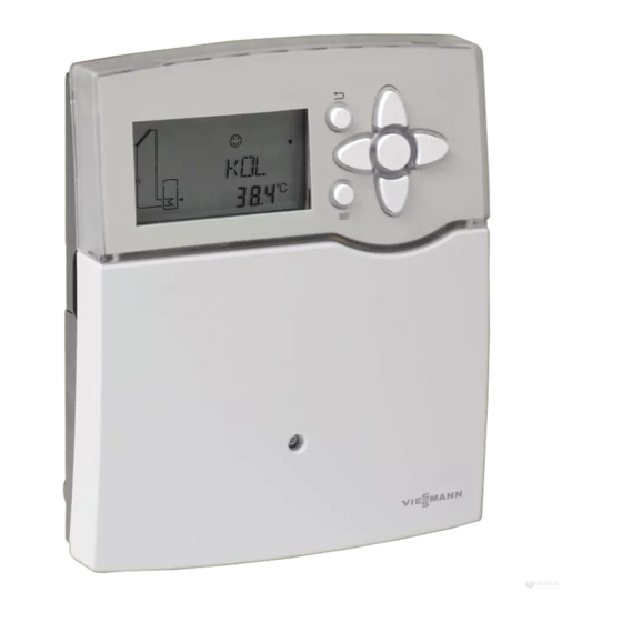
Viessmann Vitosolic 100 Installation And Service Instructions For Contractors
Electronic temperature differential controller
Hide thumbs
Also See for Vitosolic 100:
- Installation and service instructions manual (72 pages) ,
- Operating instructions for the system user (13 pages) ,
- Operating instructions manual (9 pages)

Subscribe to Our Youtube Channel
Related Manuals for Viessmann Vitosolic 100


Summary of Contents for Viessmann Vitosolic 100
- Page 1 VIESMANN Installation and service instructions for contractors Electronic temperature differential controller Vitosolic 100 Type SD1 For applicability, see the last page VITOSOLIC 100 Please keep safe. 5674 513 GB 1/2015...
- Page 2 These instructions are exclusively intended for author- For replacements, use only original spare parts ised contractors. supplied or approved by Viessmann. Work on electrical equipment must only be carried ■ out by a qualified electrician. ■...
-
Page 3: Table Of Contents
Index Index 1. Information Symbols ....................Intended use ..................Product information ................2. Installation Fitting the solar control unit ..............3. Electrical connections Overview of electrical connections ............Solar circuit pump .................. Suitable pumps ................... ■ Installation ..................■ Connection ..................■... - Page 4 Index Index (cont.) Collector cooling function "OKX" ............30 Collector minimum temperature limit "OKN" ......... 30 Frost protection function "OKF" ............31 Reverse cooling function "ORUE" ............31 Interval function "ORK" ................. 31 Heat statement "OWMZ" ............... 31 Variable speed control "RPM" ............... 32 9.
- Page 5 Product information The Vitosolic 100 is an electronic temperature differen- tial controller for dual mode DHW heating with solar collectors and oil/gas or solid fuel boilers. For special functions see chapter "Function description".
- Page 6 Installation Fitting the solar control unit Select an installation location near the DHW cylinder, taking account of the electrical connections and their cable lengths. Fig.1 6. Before closing the solar control unit, make all elec- trical connections and apply strain relief to all cables/leads (see following chapter).
-
Page 7: Overview Of Electrical Connections
Electrical connections Overview of electrical connections Danger When connecting external switching contacts and ■ Incorrect wiring can lead to serious injury from on-site components, observe the insulation require- electrical current and result in appliance dam- ments of IEC/EN 60335-1. age. ■... -
Page 8: Connection
Electrical connections Solar circuit pump (cont.) Connection Note 3-core cable with a cross-section of 0.75 mm Pumps with a power consumption in excess of 190 W Rated current: 0.8 A must be connected via an additional relay (coupling relay). The speed control for this pump must be disa- bled (see chapter "Speed control"). -
Page 9: High Limit Safety Cut-Out
Electrical connections Pump/valve at output R2 (cont.) Connection 3-core cable with a cross-section of 0.75 mm Rated current: Max. 4(2) A Fig.5 Wiring chamber of the solar control unit Pump or valve High limit safety cut-out A high limit safety cut-out in the consumer is required Note when less than 40 litres cylinder volume is available Observe the max. -
Page 10: Connection
Electrical connections High limit safety cut-out (cont.) Connection 3-core cable with a cross-section of 1.5 mm Fig.6 Wiring chamber of the solar control unit High limit safety cut-out Solar circuit pump Junction box (on site) Temperature setting Delivered condition: 120 °C High limit safety cut-out installation instructions Requires adjustment to 95 °C Collector temperature sensor... -
Page 11: Connection
Electrical connections Cylinder temperature sensor (cont.) Connection Connect the sensor to S2 (terminals 3 and 4). Extension of the connecting cable: 2-core cable with a cross-section of 1.5 mm Immersion temperature sensor For installation in the DHW cylinder, heating water buf- fer cylinder or combi cylinder Installation Fig.7... -
Page 12: Power Supply
Electrical connections Power supply Isolators for non-earthed conductors Danger ■ Install an isolator in the power cable to provide The absence of component earthing can lead to omnipolar separation from the mains for all active serious injury from electric current if an electrical conductors, corresponding to overvoltage category fault occurs. -
Page 13: Switching The Power On
Commissioning Switching the power ON 1. Check whether all electrical connections have been 4. Check which type of solar circuit pump is connected correctly made. and set parameter "RPM" accordingly (see pages 7 and 14). 2. Check that the high limit safety cut-out (if required) is connected. -
Page 14: Symbols On The Display
Commissioning Navigation through the menu (cont.) Symbols on the display These symbols are not always displayed, but appear subject to the system operating condition. The symbols may be illuminated continuously or may flash. Symbol Static Flashing System operational — Relay 1 on —... -
Page 15: Carrying Out An Actuator Test
Service scans Carrying out an actuator test Press the following keys: 5. OK to confirm. "ANL" and the relevant scheme appear on the 6. After the relay test has been completed, select display. "Auto". 2. / Select "HND 1" or "HND 2". HND 1 Relay 1 HND 2 Relay 2 3. -
Page 16: Fault Messages
Troubleshooting Fault messages Sensor faults: Possible displays: ■ Display background light flashes 88.8 Sensor short circuit – ■ The sensor symbol in the system scheme flashes 888.8 Sensor lead break quickly ■ flashes Note ¨ Further information can be called up with keys / . Example –... -
Page 17: Replacing The Mcb/Fuse
Troubleshooting Replacing the MCB/fuse Fig.12 Solar control unit wiring chamber Fuse, 4 A (slow) Open the solar control unit wiring chamber. A spare fuse is included in the fuse holder. - Page 18 Troubleshooting Replacing the MCB/fuse (cont.)
-
Page 19: Ordering Parts
Parts list Ordering parts The following details are required when ordering parts: ■ Serial no. (see type plate ■ Assembly (from this parts list) ■ Position number of the individual part within the assembly (from this parts list) -
Page 20: Parts List
Parts list Parts list 0001 0050 0060 0070 0040 0030 0010 0020 Fig.13... - Page 21 Parts list Parts list (cont.) Pos. Part 0001 Vitosolic 100 SD1 0010 Collector temperature sensor 0020 Cylinder temperature sensor 0030 Strain relief, capacitor and fuse 0040 MCB/fuse, 4 A (slow) 0050 Installation and service instructions 0060 Operating instructions 0070 System examples...
-
Page 22: Parameter Overview
Function description Parameter overview The following parameters can be set subject to the actual system configuration: Display Parameter Delivered con- Setting range System scheme dition System scheme 1 to 10 — DT E Start temperature differential for solar 8 °C 1.5 to 20 °C circuit pump R1 DT E <... - Page 23 Function description Parameter overview (cont.) Display Parameter Delivered con- Setting range System scheme dition DT 3E Start temperature differential for trans- 8 °C 0 to 20 °C fer pump R2 DT 3A Stop temperature differential for trans- 4 °C 0.5 to 19.5 °C fer pump R2 MX3E Maximum limit S3 off...
-
Page 24: System Scheme "Anl
Function description System scheme "ANL" 10 system schemes can be achieved with the solar Collector minimum temperature limit (see page 30) ■ control unit. The selection is made via parameter ■ Frost protection function (see page 31) "ANL" (see page 14). All system schemes include the ■... - Page 25 Function description System scheme "ANL" (cont.) "ANL" = 2 Dual mode DHW heating with suppression of reheating by the boiler in conjunction with control units without KM BUS and/or control of the secondary pump of an external heat exchanger Shown on display Suppression of reheating by the boiler in conjunction with control units without KM Relay R2 is started in parallel with the solar circuit pump.
-
Page 26: Anl" = 3
Function description System scheme "ANL" (cont.) Cylinder temperature sensor as PTC Cylinder temperature sensor as NTC 230 V 230 V IP 20, l, T40 IP 20, l, T40 50 Hz 50 Hz N R2 R1 N L N R2 R1 N L 13 14 15 16 17 18 19 20 21 13 14 15 16 17 18 19 20 21 Resistor 20... -
Page 27: Anl" = 4
Function description System scheme "ANL" (cont.) "ANL" = 4 Dual mode DHW heating and auxiliary function for DHW heating Shown on display Auxiliary function for DHW heating for increased DHW hygiene Connection of the transfer pump to R2 ■ Signal for starting transfer pump R2 via the KM BUS of the boiler control ■... -
Page 28: Anl" = 7
Function description System scheme "ANL" (cont.) "ANL" = 7 Dual mode DHW heating and transfer Shown on display Determining the temperature differential between collector temperature sensor S2 and cylinder temperature sensor S3. Transfer pump R2 on: ■ Start temperature differential "DT 3E" exceeded Transfer pump R2 off: ■... -
Page 29: Anl" = 10
Function description System scheme "ANL" (cont.) "ANL" = 10 Dual mode DHW heating, heating of consumer 2 via the 3-way diverter valve Shown on display Temperature differential control Determining the temperature differential between collector temperature sensor S1 and cylinder temperature sensor S2: Solar circuit pump R1 on: ■... -
Page 30: Collector Limit Temperature "Not
Function description System scheme "ANL" (cont.) Parameter Delivered condition Setting range PRIO 0 to 2 2 min 1 to 30 min tUMW 1 to 30 min 0 Priority consumer 1, no cyclical heating 1 Priority consumer 1, with cyclical heating 2 Priority consumer 2, with cyclical heating Collector limit temperature "NOT"... -
Page 31: Frost Protection Function "Okf
1. Set "OWMZ" to "On" (see page 14). 2. Check the flow rate value at the flow indicator of the Solar-Divicon at 100 % speed and set that value as "VMAX". MEDT setting Heat transfer medium Water Propylene glycol Ethylene glycol Viessmann heat transfer medium... -
Page 32: Variable Speed Control "Rpm
Function description Heat statement "OWMZ" (cont.) Setting parameters Delivered condition Setting range VMAX 5.0 l/min 0.1 to 20 l/min MEDT 0 to 3 MED % 40 % 20 to 70 % Variable speed control "RPM" Variable speed control is disabled at the factory When "DT E"... -
Page 33: Pcb
Components Replace the PCB in the stated boiler control units in conjunction with the following functions: ■ Suppression of reheating by the boiler ■ Auxiliary function for DHW heating, achieved by the solar control unit Control unit Vitotronic 200, type KW1, Part no. -
Page 34: Specification
Specification Specification Fig.15 Rated voltage 230 V~ Rated frequency 50 Hz Rated current 4 A~ Power consumption (0.7 W in standby mode) Safety category IP rating IP 20 D to EN 60 529, ensure through design/installa- tion Function Type 1 B to EN 60730-1 Permissible ambient temperature Operation 0 to +40 °C... -
Page 35: Certificates Declaration Of Conformity
Certificates Declaration of conformity We, Viessmann Werke GmbH & Co KG, D-35107 Allendorf, confirm as sole responsible body that the product Vitosolic 100 complies with the following standards: EN 55 014-1, 2 EN 60 730-1, 2, 9 EN 60 335-1... -
Page 36: Keyword Index
Variable speed control "RPM"........32 Manual operation............15 Maximum cylinder temperature control...... 27 Applicability Serial No.: 7438086 7528553 Viessmann Werke GmbH&Co KG Viessmann Limited D-35107 Allendorf Hortonwood 30, Telford Telephone: +49 6452 70-0 Shropshire, TF1 7YP, GB Fax: +49 6452 70-2780 Telephone: +44 1952 675000 www.viessmann.com...
Need help?
Do you have a question about the Vitosolic 100 and is the answer not in the manual?
Questions and answers