Advertisement
TECHNICAL INFORMATION MANUAL
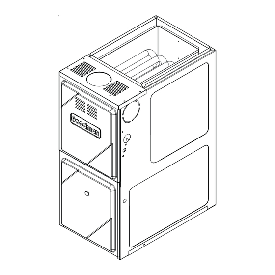
GMV8
39" 80% Gas Furnace
Upflow/Horizontal
•
Refer to RS6610004 Service Manual for installation, operation, and trouble-
shooting information.
•
All safety information must be followed as provided in the Service Manual.
•
Refer to the appropriate Parts Catalog for part number information.
This manual is to be used by qualified, professionally trained
®
HVAC technicians only. Goodman does not assume any responsi-
bility for property damage or personal injury due to improper
service procedures or services performed by an unqualified
person.
Copyright © 2006 Goodman Manufacturing Company, L.P.
Models listed
on page 3.
®
C
US
RT6622008
December 2006
Advertisement
Table of Contents

Related Manuals for Goodman GMV8


Summary of Contents for Goodman GMV8
- Page 1 This manual is to be used by qualified, professionally trained RT6622008 ® HVAC technicians only. Goodman does not assume any responsi- December 2006 bility for property damage or personal injury due to improper service procedures or services performed by an unqualified person.
-
Page 2: Product Identification
Conditioning and Refrigeration Institute (ARI). Attempting to install or repair this unit without such background may result in product damage, personal injury or death. Goodman will not be responsibile for any injury or property damage arising from improper service or service procedures. If you install or perform WARNING... - Page 3 Do not connect or use any device that is not design certified by Goodman for use with this unit. Serious property damage, personal injury, reduced...
-
Page 4: Product Design
PRODUCT DESIGN General Operation Notes: GMV8 furnaces are equipped with an electronic ignition de- 1. Category I Venting is venting at a non-positive pressure. vice used to light the burners and an induced draft blower to A furnace vented as Category I is considered a fan-as- exhaust combustion products. - Page 5 PRODUCT DESIGN Accessibility Clearances (Minimum) High Altitude Derate Unobstructed front clearanace of 24" for servicing is rec- When this furnace is installed at high altitude, the appropri- ommended. ate High Altitude orifice kit must be installed. This is re- quired due to the natural reduction in the density of both the Top clearance for horizontal confirguration - 1"...
-
Page 6: Component Identification
COMPONENT IDENTIFICATION Primary Limit Pressure Switch Flue Pipe Connection Gas Line Entrance (Alternate) Gas Line Entrance Induced Draft Blower Rollout Limit Blower Door Interlock Switch Inshot Burner Gas Manifold Circulator Blower Junction Transformer Integrated Control Module Upflow/Horizontal 10 Induced Draft Blower 1 Gas Valve 2 Gas Line Entrance (Alternate) 11 Blower Door Interlock Switch... - Page 7 PRODUCT DIMENSIONS GMV8*****XA CABINET SIZE GMV80704BX** 17½ GMV80905CX** 19.5 GMV81155CX** 19.5 All dimensions are in inches...
- Page 8 PRODUCT DESIGN PRESSURE SWITCH TRIP POINTS AND USAGE CHART 0 to 8,000 ft. Negative Pressure ID Blower With ID BLOWER MODEL Flue not Firing PRESSURE typical Sea SWITCH PART # Level Data HIGH FIRE FIRE -0.30 -0.45 B1370208 GMV80704BX** B1370209 GMV80905CX** -0.30 -0.50...
- Page 9 A large array of Amana ® brand coils are available for use with the new GMV8 furnaces, in either upflow or horizontal applications. These coils are available in both cased and uncased models, with or without a TXV expansion device. These ®...
- Page 10 PRODUCT DESIGN Thermostats: The following Amana ® brand Thermostats are suggested for use with the GMV8 Furnace Models: Two-Stage Thermostat Description Thermostat Programmable Cool Heat Hard Wired Battery Powered 1213411 1213407 1213406* * For use in dual-fuel applications with a heat pump in a fossil fuel application. It is not for use with the GMV8 as a sole heating source.
- Page 11 PRODUCT DESIGN Dual$aver Configuration and Operation: Dual$aver This furnace is capable of the following heating modes: • Single Stage (Factory Setting) • Modifi ed Two-Stage Fixed 5-Min Low Stage Auto Time (1-12 Min) Low Stage To change from the factory single-stage operation, adjust the dipswitches on the ignition control as follows: Off On Mode...
-
Page 12: Furnace Specifications
FURNACE SPECIFICATIONS MODEL GMV80704BX** GMV80905CX** GMV81155CX** Btuh Input (US) High Fire (Natural Gas) 70,000 90,000 115,000 Output (US) High Fire (Natural Gas), BTUH 57,000 74,000 93,000 Output (US) High Fire (LP), BTUH 49,000 64,000 82,000 Btuh Input (US) Low Fire (Natural Gas) 52,500 67,500 86,000... -
Page 13: Blower Performance Specifications
BLOWER PERFORMANCE SPECIFICATIONS High or Single-Stage Cooling Speeds GMV80704BX** GMV80905CX** GMV81155CX** Cooling CFM @ Cooling CFM @ Cooling CFM @ Speed Adjust Tap .1" to .8" W.C. Speed Adjust Tap .1" to .8" W.C. Speed Adjust Tap .1" to .8" W.C. Minus (-) Tap Minus (-) Tap Minus (-) Tap... - Page 14 BLOWER PERFORMANCE SPECIFICATIONS Cooling-Based Continuous Fan GMV80704BX** GMV80905CX** GMV81155CX** Cooling CFM @ Cooling CFM @ Cooling CFM @ Speed Adjust Tap .1" to .8" W.C. Speed Adjust Tap .1" to .8" W.C. Speed Adjust Tap .1" to .8" W.C. Minus (-) Tap 361** Minus (-) Tap 563**...
- Page 15 BLOWER PERFORMANCE SPECIFICATIONS GMV80704BX** (Rise Range 20 - 50 °F) Heating Low Stage CFM @ High Stage CFM @ Adjust Tap Rise Speed Tap .1" to .5" w.c. ESP .1" to .5" w.c. ESP Minus (-) Tap 1,077 Nominal 1,197 Plus (+) Tap 1,317 Minus (-) Tap...
- Page 16 BLOWER PERFORMANCE SPECIFICATIONS...
-
Page 17: Wiring Diagrams
WIRING DIAGRAMS GMV8 HIGH VOLTAGE! DISCONNECT ALL POWER BEFORE SERVICING OR INSTALLING THIS UNIT. MULTIPLE POWER SOURCES MAY BE PRESENT. FAILURE TO DO SO MAY CAUSE PROPERTY DAMAGE, PERSONAL INJURY OR DEATH. TO 115VAC/ 1 Ø /60 HZ POWER SUPPLY WITH... - Page 18 2ND S TAGE PRESS URE SW ITCH TYPICAL SCHEMATIC GMV8 MODEL FURNACES WHITE-RODGERS 50V61-289 INTEGRATED IGNITION CONTROL This schematic is for reference only. Not all wiring is as shown above, refer to the appropriate wiring diagram for the unit being serviced.
Need help?
Do you have a question about the GMV8 and is the answer not in the manual?
Questions and answers