Table of Contents
Advertisement
Quick Links
Advertisement
Table of Contents
Troubleshooting

Related Manuals for Gilera Nordwest


Summary of Contents for Gilera Nordwest
-
Page 1: Workshop Manual
WORKSHOP MANUAL NORDWEST (Nordcape in Germany) - Page 2 NOTES: In addition to this workshop manuals texts and pictures transcribed from original Piaggio/Gilera manuals, there is included a section on the various known faults with which the Nordwest/RC600 is prone to suffer. Whilst these faults were obviously not included in the original official manuals, we believed they should be a part of any publication dealing with Nordwest/RC600 maintenance.
-
Page 3: Table Of Contents
INDEX Section General information - Known faults Special tools Maintenance ENGINES Working procedures Engine removal/installation Generator - Timing belt - Gearbox selector Cylinder head - Valvetrain components Cylinder - Piston Clutch - Primary drive - Oil pump Crankcase - Gearbox - Crankshaft components FRAMES Working procedures Front Wheel... - Page 4 GENERAL INFORMATION SUB INDEX Section - Page Known faults 1 - 1 Safety procedures 1 - 2 Maintenance procedures 1 - 2 Model Identification 1 - 2 Technical data 1 - 3 Engine overhaul data 1 - 4 Torque wrench settings 1 - 5 Cables and wire passage 1 - 6...
- Page 5 KNOWN FAULTS 1 - 1 Fan touches Radiator. Remove tank, look down back of radiator & check that fan shroud has about 3mm (1/8”). The fan mountings are slotted but if there is not enough adjustment, trim the front of the shroud. Long rear engine bolts can seize.
- Page 6 A Gilera tool is available, but you can make do by using a 6mm box spanner for the lock nut, and a screwdriver long enough to work through the middle of the box spanner for the adjuster.
- Page 7 The stator is fixed to the inside of the cover so it is quite heavy. Tie it to the bike to stop it hanging on the wires. Put the bike in 5th gear and stand on the back brake, this should lock the crank well enough for you to remove the bolt from the centre of the rotor.
- Page 8 All bikes based on the 4 valve OHC single use the same type of front sprocket and 520 chain. Nordwest 14 front (part no. 328016) 43 rear (part no. 946060) Rear sprocket is dished (not flat), 5 bolt fixing. 108 links Brake fluid ALL hydraulic brakes on Gilera bikes use DOT 4.
- Page 9 The two legs are not the same. Both have a spring and oil (Nordwest has a spring ONLY on the left leg), but only the right one has the damper mechanism, so if you want to experiment with different grades of oil, you only need to change the right leg.
- Page 10 Choke Yamaha SRX choke will fit and fixes to the handlebar. Nordwest tyres Front 120/70-17R 2.1 bar (30psi) solo, 2.2 bar (32psi) 2-up Rear 160/60-17R 2.3 bar (33psi) solo, 2.4 bar (35psi) 2-up Torque your head studs You will need a torque wrench with a range up to 40 Nm and down to about 15 Nm with a socket and an extension bar that is long enough to get the wrench clear of the frame.
- Page 11 Greasing the bearings. Support front of bike and remove front wheel. Take of the callipers and tie them up to the bike somewhere. Disconnect the speedo. Take the top yoke off. (Be careful as when you do this, the forks will fall out and they are quite heavy).
-
Page 12: Maintenance
MAINTENANCE PROCEDURES Always use original Gilera spare parts and recommended lubricants. The use on non-original parts or parts not conforming to Gilera specifications may result in damage to the motorcycle. Always use the special tools designed specifically for this motorcycle. - Page 13 MODEL IDENTIFICATION Frame and engine numbers are stamped on the Manufacturers plate, as well as on the frame and engine. The engine serial number and engine size are stamped on the plate (fig. 1) found at the rear of the engine. The carburettor identification number is found on the right side of the carburettor (fig.
- Page 14 TECHNICAL DATA DIMENSIONS Overall length 2180 mm Overall width 800 mm Overall height 1180 mm Wheelbase 1415 mm Seat height 870 mm Foot pedal height 320 mm Dry weight 141 kg FRAME Detachable tubular steel single cradle; detachable tubu- lar steel rear frame. Steering column angle 27°...
- Page 15 MOTOR Monocylinder, 4 stroke, vertical cylinder Bore x stroke 98 x 74 mm Displacement 557.9 cm³ Compression ratio 10.5:1 Cylinder compression (use special tool 19.1.20524) [new] 10 - 12 bar [over 5,000 km] 9 - 11 bar 36.5 kw (49.5hp) a/at 7250 g/1’...
- Page 16 CARBURETTOR TEIKEI E30PV2A Main Choke tube diameter Main jet Idle jet Choke jet Pump jet Ø 1.1 Needle jet notch 5C58/3^ Fuel nozzle Ø 2.60 (VOO) Throttle valve 4.00 Float Weight 10.5 g Level 35 ± 1 mm This is almost certainly incorrect, we believe it should be 24 ±...
- Page 17 ENGINE OVERHAUL DATA (in mm) Piston/cylinder clearance 0.030 ÷ 0.042 Main bearings radial clearance 0.030 ÷ 0.059 Connecting rod bearings radial clearance 0.017 ÷ 0.060 Crankshaft axial clearance 0.05 ÷ 0.25 Big end axial clearance 0.15 ÷ 0.25 Gudgeon pin/piston clearance 0 ÷...
- Page 18 TIGHTENING TORQUE (in Nm) Engine Cylinder head, cylinder head cover, cylinder fixing nuts 32 ÷ 35 Timing gears fixing screw Spark plug 12 ÷ 15 Crankshaft gears fixing screw (lubricate thread with oil) Countershaft gear fixing screw (lubricate thread with oil) Free wheel fixing screw (lubricate thread with oil) Clutch fixing screw (lubricate thread with oil) Flywheel magneto fixing screw (lubricate thread with oil)
-
Page 19: Special Tools
SPECIAL TOOLS Sprocket locking wrench Camshaft oil ring installation punch 19.1.20086 19.1.20503 Puller for steering bearing lower race Camshaft pulley blocking tool 19.1.20109 19.1.20504 Flywheel puller Con-rod small end bushing 19.1.20501 installation punch 19.1.20505 Valve guide oil ring Con-rod small end bushing installation punch extraction punch 19.1.20502... - Page 20 SPECIAL TOOLS Main journal bearing extraction ring Main journal bushing extraction punch (ignition side) 19.1.20507 19.1.20511 Main journal bearing installation punch Piston support (clutch side) 19.1.20508 19.1.20512 Main journal bearing installation punch Pad for crankshaft and (ignition side) flywheel puller 19.1.20509 19.1.20513 Main journal bearing extraction ring...
- Page 21 SPECIAL TOOLS Drive gear blocking tool Valve clearance adjustment tool 19.1.20515 19.1.20522 Valve spring compression tool Valve guide extraction/installation punch 19.1.20519 19.1.20523 Oil filter removal spanner Compression check tool 19.1.20520 19.1.20524 Mounted flywheel blocking tool Oil seal installation sleeve 19.1.20521 19.1.20525...
- Page 22 SPECIAL TOOLS Engine support Pin sliding punch 19.1.20526 19.1.20530 Engine support base Battery charge density meter 19.1.20527 19.1.20564 Complete roller cage extractor Chain slack tool 19.1.20528 19.1.20565 Reamer set for valve seats Punch 19.1.20529 19.1.20566...
- Page 23 SPECIAL TOOLS Paioli fork disassembling wrench (upside down) Clutch collets tool 19.1.20599 19.1.20540 Exhaust manifold spring removal tool 19.1.20551 Complete tool kit 19.1.20563 Paioli fork fitting oil seal tool (upside down) 19.1.20598...
- Page 24 MAINTENANCE SUB INDEX Section - Page Setting engine speed at idle 3 - 1 Engine oil and filter 3 - 1 Engine oil check 3 - 1 Valves clearances 3 - 2 Cylinder compression 3 - 3 Steering bearings 3 - 3 Fairing removal 3 - 4 Carburettor ducts removal and checking...
- Page 25 MAINTENANCE MAINTENANCE PROGRAMME (*) check every 500 km 1 th PROGRAMMED OPERATIONS Tightening the engine bolt Tightening the cylinder head bolts Valve clearance control Timing belt tension check Timing belt replacement Decompression check Engine compression check Engine idle speed adjustment Spark plug check Spark plug replacement Engine oil replacement...
- Page 26 INTENTIONALLY BLANK...
- Page 27 ADJUSTMENTS Fuel level Turn over carburettor and let float rest on the needle valve’s damper spring without pressing. Check distance between bowl gasket seat and uppermost edge of the float with proper gauge. Float level = 24 ± 2 mm. Adjustment is made by bending slightly the float tongue.
- Page 28 3 - 1,2...
- Page 29 VALVE CLEARANCE ADJUSTMENTS Check and Adjust the valve clearance when the engine is cold or when the engine temperature is below 35°C. Check that the spring compressor device for ignition has a clearance. Remove the seat. Remove the fuel tank. Remove the lid of the timing system on the left side of the engine (fig.
- Page 30 COMPRESSION PRESSURE CHECK Warm up the engine. Stop the engine and remove the spark plug. Remove the kick starter decompressor on the cylinder head. Connect the pressure gauge to the spark plug hole. Turn throttle fully open. Turn engine over several times with the electric starter until the gauge measures the highest value.
- Page 31 Saddle and front side cover By operating under the rear mudguard, remove the two screws (A) and from the rear side, remove the saddle, releasing it from fixing to the tank. Remove the turn indicator lights and disconnect the relevant connections; the untighten the screws (B) fixing the side covers to the fuel tank and the two screws (C) on the radiator lower side;...
- Page 32 REMOVAL AND CHECKING OF CARBURETTORS Remove the fairing, the saddle, the fuel tank and the side covers by untightening the relevant screws. Loosen the intake manifolds clamp to the cylinder head and to intake manifold sleeve from filter box. In order to pull out the carburettor from cylinder head intake sleeves, remove the carburettor carefully.
- Page 33 AIR FILTER After the saddle removal, untighten the filter box cover screws. Remove the air filter from the filter box. Using a cloth, clean the filter box internal side. Clean the air filter by immersing it in kerosene. Wring out the filter, assuring that you don’t twist it. Using clean water, rinse out the filter and then let it dry completely.
- Page 34 TIMING BELT TENSION (Fig. 62 on previous page) In order to carry out this operation, remove the cover located on cylinder head left side. Loosen the belt tensioner nut (A) and, by means of kick lever, rotate the belt until the piston is at TDC point (compression position - fully closed valves).
- Page 35 Front brake The front brake is free of any regulation. It is advisable to verify, every 4,000 km the hydraulic fluid level on the master cylinder tank (fig. 63). Make sure that there are no leakages on brake system and that the pipes and connections are free from damage.
- Page 36 SUSPENSIONS Front suspension The telescopic fork does not need any particular care. Check periodically its efficiency by jamming on the front brake and by moving the fork up and down, like a pumping movement. The suspension functioning should be smooth and without leaks or oil blow-by.
- Page 37 SECTION 4 INTENTIONALLY BLANK...
- Page 38 ENGINE REMOVAL - INSTALLATION 5 Section - Page Working procedures 5 - 1 Engine removal 5 - 2 Engine installation 5 - 3...
- Page 39 Working procedures All operations must be carried out in a clean environment. After disassembly of the parts, wash all components in kerosene or other solvent (never use petrol) and blow dry by compressed air. Carbon deposits are removed with a brush having brass bristles or a scraper with chamfered corners.
- Page 40 ENGINE REMOVAL Hold the motorcycle by means of a support. Remove the saddle. Remove the fairing. Remove the fuel tank. Remove the side protection. Remove the crankcase under protection and the lower cradle. Loosen and remove the plug in order to drain the engine oil. Remove the radiator plug and loosen the screws on thermostat;...
- Page 41 ENGINE INSTALLATION Install the engine in reverse order of disassembly. Never re-use the same exhaust pipe gasket. Tighten the bolts to the appropriate torque. Arrange all cables and wiring correctly. Carry out the following checks and adjustment: Engine oil level. Throttle grip free travel.
-
Page 42: Generator - Timing Belt - Gearbox Selector
GENERATOR - TIMING BELT - GEARBOX SELECTOR Section - Page Disassembly 6 - 1 Inspection 6 - 2 Reassembly 6 - 2 Valve timing 6 - 2 Torque wrench settings 6 - 3... - Page 43 DISASSEMBLY Remove generator cover mounting bolts together with stator and remove cover (fig. 1). Remove the timing belt cover; loosen idler roller nut and position the idle roller in such a way as to permit the belt to come off the cam pulleys (fig. 2). Block generator rotor with special tool 19.1.20521, then loosen the mounting bolt (fig.
- Page 44 6 - 1,2...
- Page 45 6 - 1,3...
- Page 46 INSPECTION All removed components must be inspected carefully after having been thoroughly cleaned with kerosene or other solvent and dried with compressed air. All parts that show signs of damage or wear must be replaced. Be sure the pinion teeth aren’t excessively worn, freewheel group functions properly (roller race must not show signs pitting, grooving or similar damage), as well as the selector drum group.
- Page 47 TORQUE WRENCH SETTINGS Freewheel fastening bolt (lubricate thread with oil) 40 Nm. Generator rotor fastening bolt (lubricate thread with oil) 40 Nm. Chain sprocket fastening bolt (use Loctite 270) 40 Nm. Selector cam fastening bolt 40 Nm. Tensioner pulley fastening nut 28-30 Nm.
-
Page 48: Cylinder Head - Valvetrain Components
CYLINDER HEAD - VALVETRAIN COMPONENTS 7 Section - Page Diagram 7 - 1 Disassembly 7 - 2 Inspection 7 - 2 Reassembly 7 - 3 Torque wrench settings 7 - 3... - Page 49 7 - 1...
- Page 50 DISASSEMBLY Pull off the water passage coupler mounted on the right side of the head and remove the O-ring found under the coupler fitting (fig. 1). Remove timing belt cover; loosen idle roller nut and position the idle roller in such a way as to permit the belt to come off the two cam pulleys (fig.
- Page 51 7 - 2,2...
- Page 52 7 - 2,3...
- Page 53 INSPECTION After a thorough cleaning of all parts, place the components on the bench and inspect them carefully. All those parts that show signs off wear and/or damage must be replaced. Head Scrape the surface and remove traces of head gasket and remove all carbon deposit in the combustion chamber.
- Page 54 7 - 2,5...
- Page 55 REASSEMBLY Assemble in reverse order of disassembly. Pay close attention to the following points: Every component must be installed in the same position before it was removed. This is most important for rocker arms, valves, spring retainer and collets. Do not mix the two camshaft pulleys: the one marked with an “S” is for exhaust: the one marked with an “A”...
-
Page 56: Cylinder - Piston
CYLINDER - PISTON Section - Page Diagram 8 - 1 Disassembly 8 - 2 Inspection 8 - 2 Reassembly 8 - 2... - Page 57 8 - 1...
- Page 58 DISASSEMBLY Remove the head group, gasket and rubber anti-vibration devises, as de- scribed in section 7. Remove the water pump, found on the left of the cylinder (fig. 1). Remove the thermostat’s housing on the front of the cylinder (fig. 2). Lift the cylinder by hand.
- Page 59 8 - 2,2...
- Page 60 Piston rings The rings are removed only when necessary. These components are very fragile and must be removed and installed very carefully. To check for ring wear, take each ring and place it “squarely” inside the lower part of the cylinder. Measure the end gap with a feeler gauge (fig. 9). Max.
- Page 61 8 - 2,4...
-
Page 62: Clutch - Primary Drive - Oil Pump
CLUTCH - PRIMARY DRIVE - OIL PUMP Section - Page Diagram 9 - 1 Disassembly 9 - 2 Inspection 9 - 2 Reassembly 9 - 3 Torque wrench setting 9 - 3 7 - 1,5... - Page 63 9 - 1...
- Page 64 DISASSEMBLY Drain the oil. Loosen the kick starter bolt; remove cover plate mounting screws and remove right side cover of the engine block. Remove the seeger ring and the thrust bearing (fig. 1). Block the drive gear of the primary drive with special tool 19.1.20515. Remove clutch assembly mounting screw and washer (fig.
- Page 65 9 - 2,2...
- Page 66 9 - 2,3...
- Page 67 REASSEMBLY Assemble in reverse order of disassembly. Pay close attention to the following points: The crankshaft thrust ring is installed with the grooves facing out and it’s notch in the cover’s seat. When mounting the balance shaft, align it properly. To do this, align the internal markings with the ones on the shaft together with the external markings, as shown in (fig.
-
Page 68: Crankcase - Gearbox - Crankshaft Components
CRANKCASE - GEARBOX - CRANKSHAFT COMPONENTS Section - Page Diagram 10 - 1 Disassembly 10 - 2 Inspection 10 - 3 Reassembly 10 - 3 Torque wrench settings 10 - 3... - Page 69 10 - 1...
- Page 70 DISASSEMBLY Make sure all necessary components are removed, then remove all bolts that join the two halves of the cases. Open the crankcase and if necessary use a plastic or rubber mallet to loosen it (carefully hit at the joint of the cases and/or at the end of the gearbox shafts).
- Page 71 10 - 2,2...
- Page 72 INSPECTION After a thorough cleaning of all parts, inspect all components carefully. All those parts that show sign of wear and/or damage must be replaced. Crankshaft The crankshaft must be replaced if found damaged or worn. Connecting rod Install the half bearings and mount the connecting rod cap by tightening the nuts to the proper torque setting (28 to 32 Nm).
- Page 73 Crankcase Accurately measure the internal diameter of each main journal with a micrometer. Diameter at mounting = 40.030 ÷ 40.046 mm. Once the bearing and main journal internal diameter is known, it is possible to calculate the gap of the two components. Clearance at mounting = 0.030 ÷...
-
Page 74: Front Wheel
FRAMES Section Working procedures Front wheel Front suspension - Steering Rear suspension - Rear wheel Brakes... -
Page 75: Working Procedures
WORKING PROCEDURES All operations must be carried out in a clean environment. After disassembly of parts, wash all components in kerosene or other solvent (never use petrol) and blow dry with compressed air. All operations must be carried out in a precise order; mark all components to be removed one at a time, or place them in separate containers so as to mount them in the same position as prior to disassembly. -
Page 76: Front Wheel
FRONT WHEEL Section - Page Diagram 12 - 1 Disassembly 12 - 2 Reassembly 12 - 2 Technical data 12 - 3 Trouble shooting 12 - 4... - Page 77 12 - 1...
- Page 78 DISASSEMBLY Disconnect the speedometer cable. Loosen the lock-spindle screws on the right side. By means of a pin, loosen and slide out the wheel spindle. Remove the wheel. Warning: After the wheel removal, never move the front brake lever. This is to facilitate, when installing, the disc fitting into the pads. Spindle straightness inspection Place the spindle on two “V”...
- Page 79 Bearings reassembly Fill, with grease, the bearing housing. First insert the right side bearing, then the spacer and, finally, the left side bearing. Apply grease inside to the dust protection seal. Fit the dust protection seal. Install the tachometer gear seal into the wheel hub, aligning the tags with the grooves.
- Page 80 TROUBLE SHOOTING Stiff steering: Steering bearing adjusting ring nut too tight. Faulty steering sleeve bearings. Tyre pressure too low. Tends to steer to one side and has poor handling: Bent front forks. Bent front wheel spindle. Wheel not mounted properly. Different quantity of oil in the two fork legs.
- Page 81 SUSPENSION - STEERING Section - Page Handlebar 13 - 1 Steering sleeve 13 - 2 Trouble shooting 13 - 3 Paioli fork 13 - 4...
-
Page 82: Front Suspension - Steering
FRONT SUSPENSION - STEERING 13 HANDLEBAR Removal Remove the clamps, the clutch lever, the front brake master cylinder, lights, switches and throttle grip. Remove the upper plates, caps and the handlebar (fig. 31). Installation Check that the rubber washers, placed between the fork upper plate and the handlebar lower supports, are not worn. - Page 83 STEERING SLEEVE After disassembling the fairing components, the wheel; and the handlebar, dis- connect the electrical connections, then: Unscrew the steering sleeve nut then remove the washer. Remove the fork upper plate. Remove the steering nut. Remove the upper bearing. Slide off the fork unit (with steering sleeve) from lower side.
- Page 84 TROUBLE SHOOTING Stiff steering: Steering bearing adjusting ring nut too tight. Faulty steering sleeve bearings. Tyre pressure too low. Motorcycle tends to steer to one side and has poor handling: Bent front fork. Bent front wheel spindle. Wheel not fitted correctly. Unlike quality of oil in the fork legs.
- Page 85 PAIOLI FORK After the front fairing parts removal, remove the upper and lower screws fixing the stanchion to the fork plates, then remove the stanchion. Oil seal removal and replacement (fig. 36) Loosen the upper plug “A” then, when holding the plug, untighten the inner stanchion locking nut “B”...
- Page 86 In order to avoid any abnormal leakages, it is suitable to don’t carry out the thin plates locking too strong. Installation (fig.36) Insert the rod “N” together with the thin plates into the hydraulic cartridge “O”. Fit on the rod the lower plug “Q” together with the relevant bushing, then install the lock ring.
- Page 87 REAR SUSPENSION - WHEEL 14 Section - Page Troubleshooting 14 - 1 Wheel 14 - 1 Rear damper 14 - 2 Final drive 14 - 3...
- Page 88 TROUBLESHOOTING Motorcycle oscillations and vibrations Deformed rim Loose or worn wheel bearings Defective tyre Incorrect tyre pressure Incorrect chain adjustment cams Slack wheel spindle Worn fork spindle bearings Frame of fork deformation Incorrect wheel balancing Suspension too soft Weakened spring Poor quantity of fork oil Suspension too stiff Bent absorber shock rod...
- Page 89 REAR ABSORBER SHOCK The rear shock absorber is constituted by an oil dynamic unit, with an additional tank (for the Nordwest model, is without tanks), and normally is without any servicing. The spring pre-load can be adjusted by means of two ring nuts situated on the upper side (fig.
- Page 90 FINAL DRIVE Drive chain Chain life depends on lubrication and appropriate tension. Neglecting the above mentioned checks will result in wear and damage of both the drive and driven sprockets thereby compromising motorcycle performance. A chain inspection must be carried out prior to riding off. Chain adjustment must be executed every 2,000 km.
- Page 91 Chain status inspection If a part of the chain or the drive/driven sprockets show signs of wear, replace components. Check chain stiffness; if it is stiff, then clean with appropriate products or diesel fuel and let dry thoroughly. Avoid “knots” and replace if chain remains stiff. Check for possible damage to the side plates and for excessive play in the pins and rollers.
- Page 92 BRAKES Section - Page Working procedures 15 - 1 Trouble shooting 15 - 1 Master cylinder 15 - 2 Calliper 15 - 3 Disc 15 - 3 Pad replacement 15 - 5...
- Page 93 WORKING PROCEDURES Fluid drainage Connect a tube to the bleeder valve. Loosen the bleeder valve and pump with lever. Stop pumping when no more fluid flows out of the bleeder valve. Brake fluid spilled on the disc or pads will reduce braking capability. If this should happen, throw away the pads and clean the disc thoroughly with a proper solvent.
- Page 94 MASTER CYLINDER Removal Drain the brake fluid. Disconnect the brake pipe by loosening the connecting nut. Pay attention that the brake fluid does not come in contact with painted, plastic or rubber parts. When operating on brake system, always protect the above parts.
- Page 95 BRAKE CALLIPER Removal Place a clean container under the calliper, then disconnect the brake pipe. Pay attention that brake fluid does not come in contact with painted parts. Remove the calliper by loosening the securing screws to the fork (fig. 32) and to the plate secured to the fork (fig.
- Page 96 15 - 4...
- Page 97 PADS PLACEMENT In order to obtain the correct pressure, always replace both pads together. Warning Always use GILERA original parts. Grease on brake linings reduce he brake’s performance. The procedures are the same for both brakes. Remove the upper cover “A” (fig. 37), then dismantle the seeger ring “B”.
-
Page 98: Battery - Charging Circuit
BATTERY - CHARGING CIRCUIT 16 Section - Page Battery voltage 16 - 1 Battery charging 16 - 1 Charging circuit 16 - 1 Troubleshooting 16 - 2 Battery removal 16 - 2 Battery installation 16 - 2... - Page 99 .BATTERY VOLTAGE With the engine on “OFF” position, place the voltmeter red colour lead on the battery positive (+) terminal and the black colour lead on the battery negative (-) terminal. Battery voltage should be 12 ÷ 13 V. When battery voltage is lower than 11 V, check the charging system. Warning: When the battery voltage is lower than 6 V, automatically a device will stop the ignition.
- Page 100 Rectifier check It is a three-phase rectifier. Check the diode’s efficiency by disconnecting the connector end (fig. 3). Connect the positive (+) prod of the ohmmeter to the red wire and the negative (-) one to the white wires (one at a time) (fig. 4). With efficient diodes, the pointer should not move.
- Page 101 Alternator stator coil check Disconnect the alternator wires (fig. 5). Remove the alternator stator coil. Check for continuity between the two wires of the alternator stator coil (fig. 6). Check for continuity between the wires of the alternator stator rectifier (fig. 7). Check if there is no continuity, on the contrary, between the above mentioned stator coil wires and ground (figs.
- Page 102 WARNING The electrolyte level must be checked periodically; top up with distilled water if necessary. Remove the battery from the frame when charging. Keep battery away from sparks and flames due to the hydrogen produced by the battery. All charging components may be tested without removal. TROUBLESHOOTING No voltage with the key in the “ON”...
- Page 103 BATTERY REINSTALLATION Install the battery in its compartment in the frame. Connect the positive (+) cable to the battery’s positive (+) terminal; connect the negative (-) cable to the battery’s negative (-) terminal. Block the battery with securing rubber. Apply some clean grease to the battery terminals. Place the battery breather tube in it’s original position.
-
Page 104: Ignition System
CAPACITY DISCHARGE IGNITION SYSTEM & INDUCTIVE DISCHARGE IGNITION SYSTEM 17 Section - Page Capacity discharge ignition Description 17 - 1 Inspection 17 - 2 Spark plug 17 - 2 Troubleshooting 17 - 3 Inductive discharge ignition Description 17 - 4 Inspection 17 - 5 Spark plug... - Page 105 CAPACITY DISCHARGE IGNITION SYSTEM Description This ignition system is capacitive discharge type. This ignition system is constituted by a flywheel magneto, by a C.D.I. Box and an HT coil. The tension, created by charging coil, is stored into a condenser. The signal, created from pick-up windings, is sent to the electronic box which discharge the condenser stored current on the HT coil primary winding;...
- Page 106 CHECKS The whole ignition system can be tested for eventual malfunctioning or weak spark. If the electrodes generate a suitable spark, the whole electronic system works regularly. If there is no spark, carry out the testing of each component until the problem will be solved. Follows the troubleshooting schedule until finding the trouble cause.
- Page 107 HT Coil test Remove the petrol tank and seat. Disconnect the electrical wires and spark plug cap. Remove the ignition coil. Measure the resistance between coil terminal + and -. Standard resistance: 0.2 ÷ 0.3 Ω ±10% at 20°C. If there is no continuity, replace coil. Measure the resistance between the electrical wire terminal and the high tension wire without spark plug cap.
- Page 108 TROUBLESHOOTING The engine start to run but not regularly The following parts could be faulty: HT Coil. Pulses generator. Electronic control box. Condenser charge unit. HT cable. Spark plug. Loose wires. Incorrect spark advance. Loose or incorrectly fitted flywheel pulses generator. Electronic control unit faulty.
- Page 109 INDUCTIVE DISCHARGE IGNITION SYSTEM Description The ignition system is inductive discharge type. This ignition system consists of a control unit and HT coil. The impulsive tension is generated by control unit; this control unit is supplied by the battery. The pick-up signal is sent to the control unit. Control unit All the timings, spark advance, revolution reductor operations are carried out by a microprocessor.
- Page 110 CHECKS The whole ignition system can be tested for eventual malfunctioning or weak spark. If the electrodes generate a suitable spark, the whole electronic system works regularly. If there is no spark, carry out the testing of each component until the problem will be solved. Follows the troubleshooting schedule until finding the trouble cause.
- Page 111 Control unit test A common tester results isn’t able to take any readings; therefore it is advisable to replace the CDI control unit. Spark plug cap resistance: 1 kΩ (fig. 5). Replace if out of specification. Spark plug Check spark plug condition: in case it is overheated, fouled or worn, replace it.
-
Page 112: Electric Starter
ELECTRIC STARTER Section - Page Starter motor 18 - 1 Casing insulation check 18 - 1 Troubleshooting 18 - 1... -
Page 113: Electric Starter
ELECTRIC STARTER STARTER MOTOR Removal The electric starter may be removed with the engine in the frame. Put ignition switch in the “OFF” position and disconnect the battery’s negative (-) cable prior to starter motor maintenance. Disconnect the starter’s cable. Loosen the starter’s mounting bolts and remove the starter. - Page 114 ELECTRIC STARTER 18 - 1,2...
-
Page 115: Switches - Horn - Lights
SWITCHES - HORN - LIGHTS 19 Section - Page Working procedures 19 - 1 Instruments 19 - 1 Headlamp 19 - 1 Tail lamp 19 - 1 Turn signal indicators 19 - 1 Neutral switch 19 - 1 Temperature indicator 19 - 2 Oil pressure sensor 19 - 2... - Page 116 WORKING PROCEDURES All the plastic plugs are fitted with blocking tongues that must be released before removing the plugs and aligned when the plugs are re-connected. In order to isolate an electrical problem, always check the continuity in the current path. A continuity check is usually executed without removing the component from the motorcycle;...
- Page 117 19 - 1,2...
- Page 118 TEMPERATURE INDICATOR Disconnect the wire from the temperature sensor and ground it. Turn the ignition switch to “ON”; the needle on the temperature indicator must move to the “H” side (red). Do not ground the temperature sensor wire for more than a few seconds or there may be damage to the temperature gauge.
- Page 119 BRAKE LIGHT SWITCHES Front Disconnect the switch wires and check for continuity. The switch is working properly when there is continuity while actuating the brake. Rear Disconnect the switch coupler and check for continuity in the wires. The switch is working properly when there is continuity when actuating the rear brake lever.
-
Page 120: Troubleshooting
TROUBLESHOOTING Section - Page Engine doesn’t start or starts with difficulty 20 - 1 Poor performance 20 - 2 Poor road handling 20 - 3... - Page 121 TROUBLESHOOTING 20 - 1...
- Page 122 TROUBLESHOOTING Continued on page 20 - 2,2 20 - 2,1...
- Page 123 TROUBLESHOOTING Continued from page 20 - 2,1 20 - 2,2...
- Page 124 TROUBLESHOOTING 20 - 3...
-
Page 125: Electrical System
Section - Page Wiring colours/list of components Nordwest/RC600 ‘91 21 - 1 Diagram 21 - 1 Wiring colours/list of components Nordwest / 600 93 21 - 2 Diagram 21 - 2 Wiring colours/list of components Inductive discharge 21 - 3... - Page 126 NORDWEST / RC600 ‘91 WIRING COLOURS LIST OF ELECTRICAL SYSTEM COMPONENTS Twin lamp lighting group 12V - 35/35W Light Blue Two level bulb 12V - 60/55W Orange Front parking light bulb 12V - 3W Light Blue/Black White Front and rear turn indicators...
- Page 127 21 - 1,2...
- Page 128 NORDWEST 600 / 93 WIRING COLOURS LIST OF ELECTRICAL SYSTEM COMPONENTS Twin lamp lighting group Light Blue Two level halogen bulb 12V - 55/60W Orange Light bulb 12V - 5W Light Blue/Black White Turn indicators Dark Blue Light bulb 12V - 10W...
- Page 129 21 - 2,2...
- Page 130 NORDWEST INDUCTIVE DISCHARGE IGNITION SYSTEM WIRING COLOURS LIST OF ELECTRICAL SYSTEM COMPONENTS Twin lamp lighting group Light Blue Two level halogen bulb 12V - 55/60W Orange Light bulb 12V - 5W Light Blue/Black White Turn indicators Dark Blue Light bulb 12V - 10W...
- Page 131 21 - 3,2...
-
Page 132: Additional Information
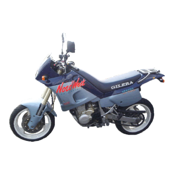
This additional information comes from the “Nordwest Fact Sheet” which was widely distributed. The Nordwest was derived from the RC600 (1991 spec). Many parts are common and basically by changing the wheels, forks, rear shock and brakes, the bike was transformed from serious trail bike to serious street fighter with excellent performance on the tarmac. - Page 133 Electrical system Ignition Two systems were used; Early bikes up to 228 51763 use the Captive Discharge system. Bikes 228 51764 and on use the Inductive Discharge system. Capacitive Discharge: Recognisable by; 6 wires from ignition switch, separate rev limiter box (pink and green wires), 9 wires from ignition box, 3 groups of wires from alternator, 2 fuses.
- Page 134 Bulbs: All 12 V Head Light: 60/65w halogen H4 type Tail/stop: 5/21w Indicator: 10w bayonet Side light: Instruments: 2w mini cap less Warning: 1.2w mini cap less Fuses: Capacitive Ignition 2 X 15w Inductive Ignition 1 X 20w, 1 X 15w, 1 X 7.5w Rear suspension: Boge progressive mono shock.
- Page 135 Rear brake disc: Part no. 343413 (single fixed disc) Diameter: 240 mm Thickness (new): 4.5 mm Wear limit: 3.6 mm Calliper: Twin piston Brake fluid: DOT 4 (should be changed every two years) Piston diameter: 32 mm Piston wear limit: 0.05 mm Pad: Part no.
- Page 136 341754 Float valve These Teikei carbs are used on some Yamaha big singles, so Yamaha dealers could be another source of parts. Nordwest & RC600 use same items RC600 ‘89 refers to ‘89 & ‘90 versions (not Norwest body work)
Need help?
Do you have a question about the Nordwest and is the answer not in the manual?
Questions and answers