Table of Contents
Advertisement
GILERA WOULD LIKE TO THANK YOU
for choosing one of its products. We have prepared this booklet to help you to get the very best from your scooter. Please read it carefully before riding
the scooter for the first time. It contains information, tips and precautions for using your scooter. It also describes features, details and devices to assure
you that you have made the right choice. We believe that if you follow our suggestions, you will soon get to know your new vehicle and it will serve you
well for a long time to come. This booklet forms an integral part of the scooter; should the scooter be sold, it must be transferred to the new owner.
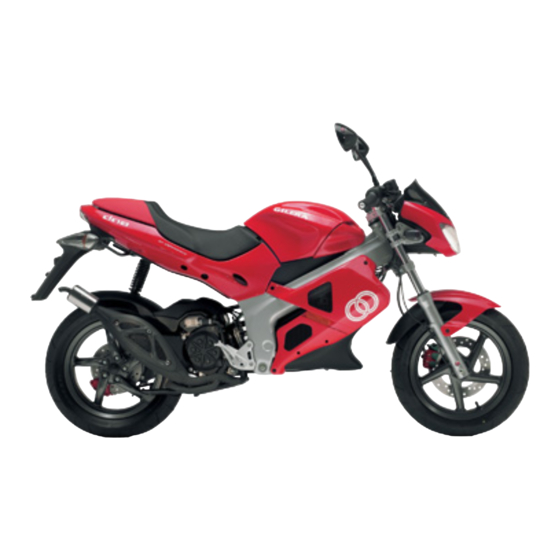
DNA
Advertisement
Table of Contents

Related Manuals for Gilera DNA


Summary of Contents for Gilera DNA
- Page 1 GILERA WOULD LIKE TO THANK YOU for choosing one of its products. We have prepared this booklet to help you to get the very best from your scooter. Please read it carefully before riding the scooter for the first time. It contains information, tips and precautions for using your scooter. It also describes features, details and devices to assure you that you have made the right choice.
- Page 2 The instructions given in this manual are intended to provide a clear, simple guide to using your scooter; this booklet also details routine maintenance procedures and regular checks that should be carried out on the vehicle at an authorised Dealer or Service Centre. The booklet also contains instructions for simple repairs.
- Page 3 Personal safety Failure to completely observe these instructions will result in serious risk of personal injury. Safeguarding the environment Sections marked with this symbol indicate the correct use of the vehicle to prevent dam- aging the environment. Vehicle intactness The incomplete or non-observance of these regulations leads to the risk of serious damage to the vehicle and sometimes even the invalidity of the guarantee.
-
Page 5: Table Of Contents
INDEX VEHICLE..................Secondary air system............... 31 Dashboard................Cooling fluid level..............31 Instruments................Checking the brake oil level............33 Clock..................10 Battery..................34 Digital lcd display..............10 Checking the electrolyte level..........35 Setting the total and trip odometers........10 Long periods of inactivity............36 Setting the hour/minutes function.......... -
Page 7: Vehicle
Chap. 01 Vehicle... -
Page 8: Dashboard
Dashboard (01_01) A = Rev counter B = Low-fuel warning light C = Turn signal warning light D = Low-oil warning light E = Lights switch F = Starter button G = High-beam warning light H = Horn button I = Turn signal switch L = Ignition key-switch M = Digital dashboard N = Lights setting switch... -
Page 9: Instruments
01_01 Instruments (01_02) A = Odometer B = Speedometer C = Fuel gauge D = Coolant temperature gauge 01_02... -
Page 10: Clock
Clock The time is displayed even when the engine is off (as the clock is powered directly by the vehicle's battery); it is displayed in a 12-hour mode with "AM" or "PM" subscripts. To adjust the time, proceed as follows: press the "MODE" button until the time is dis- played, hold down the "CLOCK"... -
Page 11: Setting The Hour/Minutes Function
2. PARTIAL- The word "TRIP" appears and Km/h or mph. The value can be changed by pressing and holding the "SET" button for longer than three sec- onds. N.B. IT IS POSSIBLE TO CHANGE THE DISPLAY FROM KILOMETRES (km/h) TO MILES (mph) BY PRESSING THE "MODE"... -
Page 12: Key Switch
N.B. THE TIME SETTING IS IN «P.M.» MODE, WHICH MAY BE IDENTIFIED BY THE NUMBER "0" FOLLOWING "11". IN «A.M.» MODE, THE NUMBER «12» IS DIS- PLAYED. CAUTION THE «CLOCK» BUTTON IS ENABLED ONLY WHEN THE ENGINE IS OFF AND THE KEY IS TURNED TO «ON». -
Page 13: Releasing The Steering Wheel
Releasing the steering wheel Reinsert the key and turn it to «OFF». CAUTION DO NOT TURN THE KEY TO «LOCK» OR «OFF» WHILE RIDING. Switch direction indicators (01_04) To set the left turn indicators flashing, move lever «B» to the left; to set the right turn indicators flashing, move it to the right. -
Page 14: Light Switch
Light switch (01_06) 0 = Low beam and side light 1 = High beam and side light 01_06 Start-up button (01_07) Press the button «E» to start the engine, after pulling one of the two brake levers 01_07... -
Page 15: Lifting The Helmet Bay
Lifting the Helmet Bay (01_08) To access the fuel and water expansion tanks, insert the key into lock "A", turn it anticlockwise and tilt the helmet bay door forward. Secure the door with the prop lo- cated inside the helmet bay, on the left hand side. 01_08 Keys (01_09) The vehicle comes with one key and one copy for the ignition key-switch, and the seat... -
Page 16: Identification
Identification (01_10, 01_11) The identification numbers consist of a prefix stamped on the chassis and on the en- gine, followed by a number. They should always be given when requesting spare parts. We recommend that you check that the prefix and chassis number stamped on the vehicle correspond with those in the vehicle documents. -
Page 17: Use
Chap. 02... -
Page 18: Checks
Checks Before riding the vehicle, check: 1. The fuel and oil tanks are full. 2. The rear hub oil level. 3. The tyres are inflated correctly. 4. The headlight, taillight and turn signals are working properly. 5. The front and rear brakes are in riding order. 6. -
Page 19: Tyre Pressure
CAUTION USING OILS OTHER THAN THOSE RECOMMENDED CAN SHORTEN THE LIFE OF THE ENGINE. Recommended products AGIP CITY TEC 2T 02_02 Mixer oil synthetic oil for 2-stroke engines: JASO FC, ISO-L-EGD Characteristic Oil tank Plastic, capacity ~ 1.350 lt. (including reserve ~ 0.400 lt.). Fuel tank Plastic, capacity ~ 9 lt. -
Page 20: Running In
Characteristic Front wheel pressure: 1.8 bar Rear wheel pressure: 2 bar Running in (02_04) WARNING DURING THE FIRST 1000 KM DO NOT RIDE THE VEHICLE OVER 80% OF ITS MAXIMUM SPEED. AVOID TWISTING THE THROTTLE GRIP FULLY OR KEEP- ING A CONSTANT SPEED ALONG LONG SECTIONS OF ROAD. AFTER THE FIRST 1000 KM, GRADUALLY INCREASE SPEED UNTIL REACHING THE MAX- IMUM PERFORMANCE. -
Page 21: Starting Up The Engine
Starting up the engine (02_05) The engine is fitted with an automatic continuously variable transmission (CVT) and clutch. For this reason, the throttle must not be twisted when the engine is being star- ted; to pull away, progressively increase the throttle opening. The vehicle is also equipped with a vacuum fuel tap and an electric choke device which are automatically engaged when the engine is running. -
Page 22: Difficult Start Up
Difficult start up (02_06) Possible causes for engine starting difficulties and suggested actions: 1.Carburettor flooded. Place the vehicle on the centre stand and check that the rear tyre is off the ground. Open the throttle fully and press the starter button for five sec- onds and then stop for five seconds. -
Page 23: Stopping The Engine
Stopping the engine (02_07) Stop acceleration, then turn the key switch "D" to "OFF " to turn off the engine (ex- tractable key). CAUTION DUE TO THE HIGH TEMPERATURES THE CATALYTIC CONVERTER CAN REACH, ALWAYS TAKE CARE, WHEN PARKING THE SCOOTER, THAT THE 02_07 EXHAUST DOES NOT COME INTO CONTACT WITH FLAMMABLE MATERIALS, TO AVOID SERIOUS BURNS. -
Page 24: Automatic Transmission
CAUTION DO NOT SWITCH OFF THE ENGINE WHILE THE VEHICLE IS MOVING. UN- BURNED FUEL COULD ENTER THE CATALYTIC CONVERTER AND BURN, CAUSING IT TO OVERHEAT AND POSSIBLY DESTROYING IT. Automatic transmission To ensure simple, pleasurable riding, the vehicle is equipped with automatic trans- mission with regulator and centrifugal clutch. -
Page 25: Safe Driving
Safe driving WARNING SOME SIMPLE TIPS ARE PROVIDED BELOW THAT WILL ENABLE YOU TO USE YOUR SCOOTER ON A DAILY BASIS IN GREATER SAFETY AND WITH MORE PEACE OF MIND. < Your ability and your knowledge of the vehicle form the basis of safe riding. We rec- ommend trying out the vehicle in traffic-free zones to get to know your vehicle completely. - Page 26 8. Any elaboration that modifies the vehicle's performances, such as tampering with original structural parts is strictly forbidden by law, and renders the vehicle not con- forming to the approved type and therefor dangerous to ride. CAUTION DO NOT FORGET THAT DRIVING IN A STATE OF DRUNKENNESS, OR WHEN UNDER THE EFFECT OF DRUGS OR CERTAIN MEDICINES, CAN BE EXTREME- LY DANGEROUS FOR ONESELF AND FOR OTHERS.
-
Page 27: Maintenance
Chap. 03 Maintenance... -
Page 28: Hub Oil Level
Hub oil level (03_01, 03_02, 03_03) To check the hub oil level, proceed as follows: 1. Place the scooter on its stand on a level surface; 2. Unscrew the dipstick «A», dry it with a clean rag and then reinsert it, screw- ing it tightly into place;... -
Page 29: Tyres
Rear hub oil SAE 80W/90 Oil that exceeds the requirements of API GL3 specifications Characteristic Rear hub oil Quantity: approx. 85 cc Tyres Check the inflation pressure of both tyres periodically. The tyres are fitted with a wear indicator and must be replaced as soon as such indicators become visible through the tyre's tread. -
Page 30: Spark Plug Dismantlement
Rear wheel pressure (driver and gear) 2 bar Spark plug dismantlement (03_04) Detach the spark plug cap, shown in the figure, and remove the spark plug using the box-spanner provided. Upon refitting, engage the park plug thread at the correct angle and screw it in by hand, using the box-spanner for tightening. -
Page 31: Removing The Air Filter
100°C. If the temperature does not decrease or if indeed more bars light up, shut the engine off, let it cool down and 03_06 check the coolant level; if this is within the prescribed limit, contact a Piaggio-Gilera... - Page 32 The cooling system must therefore be inspected by an Authorised Piaggio-Gilera Service Station. The coolant must be replaced every 2 years. For this operation, contact of an Authorised Piaggio-Gilera Service Station.
-
Page 33: Checking The Brake Oil Level
A decrease of the brake fluid level may be caused by the wear of the pads. If the level is below the min mark, we recommend that you contact an Authorised Piaggio-Gilera Service Station to have your braking system checked. If necessary, top-up the fluid level as follows. -
Page 34: Battery
WARNING IN NORMAL CLIMATIC CONDITIONS IT IS ADVISABLE TO REPLACE THE ABOVE-MENTIONED FLUID EVERY 2 YEAR. NEVER USE BRAKE FLUID CON- TAINED IN CONTAINERS WHICH ARE ALREADY OPEN OR PARTIALLY USED. CAUTION THE BRAKING CIRCUIT FLUID IS HIGHLY CORROSIVE. THEREFORE, WHEN TOPPING IT UP, AVOID LETTING IT COME INTO CONTACT WITH THE PAINTED PARTS OF THE VEHICLE. -
Page 35: Checking The Electrolyte Level
WARNING THE ELECTROLYTE CONTAINS SULPHURIC ACID: AVOID CONTACT WITH EYES, SKIN AND CLOTHES. IN THE CASE OF ACCIDENTAL CONTACT, RINSE WITH ABUNDANT OF WATER AND CONSULT A DOCTOR. CAUTION IN ORDER TO AVOID DAMAGING THE ELECTRICAL SYSTEM, NEVER DISCON- NECT THE WIRING WHILE THE ENGINE IS RUNNING. DO NOT TIP THE SCOOT- ER TOO MUCH IN ORDER TO AVOID DANGEROUS LEAKAGE OF BATTERY ELECTROLYTE Checking the electrolyte level... -
Page 36: Long Periods Of Inactivity
Long periods of inactivity Battery performance will decrease if the vehicle is not used for a long time. This is the result of the natural phenomenon of battery discharging plus residual absorption by vehicle components with constant power consumption. Poor battery performance may also be due to environmental conditions and the cleanness of the poles. -
Page 37: Fuses
WARNING SPENT BATTERIES ARE HARMFUL FOR THE ENVIRONMENT. COLLECTION AND DISPOSAL SHOULD BE CARRIED OUT IN COMPLIANCE WITH CURRENT REGULATIONS. Fuses The electric system is protected by a 7.5A fuse located underneath the seat and be- hind the battery. The ignition, starter motor, automatic choke, and head and taillight systems are not protected by the fuse. - Page 38 Power: 12V - 35W Quantity: 1 High-beam light bulb Type: H8 Power: 12V - 35W Quantity: 1 Front tail light bulb Type: All glass Power: 12V - 3W Quantity: 2 Front turn indicator bulb Type: Spherical Power: 12V - 10W Quantity: 1 RHS + 1 LHS Rear turn indicator light bulb Type: Spherical...
-
Page 39: Front Light Group
Front light group (03_10, 03_11, 03_12) To gain access to the headlight bulb (2 dual-filament light bulbs for high and low- beam), it is necessary to proceed as follows: remove the front cover "A" by loosening the 6 fixing screws located behind it. Remove the headlight by loosening the 3 screws, "B", one of which is located underneath the headlight. -
Page 40: Headlight Adjustment
Headlight adjustment (03_13, 03_14) Proceed as follows: 1. Place the vehicle in running order and with the tyres inflated to the prescribed pres- sure, on a flat surface 10 m away from a white screen situated in a shaded area, making sure that the longitudinal axis of the vehicle is perpendicular to the screen;... -
Page 41: Rear Optical Unit
Rear optical unit (03_15) N.B. IF MISTING IS NOTICED ON THE INSIDE OF THE HEADLAMP GLASS, THIS DOES NOT INDICATE A FAULT AND IS RELATED TO THE HUMIDITY AND/OR TO LOW TEMPERATURES. THE PHENOMENON SHOULD QUICKLY DISAPPEAR WHEN THE LIGHT IS SWITCHED ON. -
Page 42: Idle Adjustment
Idle adjustment (03_17, 03_18) The idle speed is adjusted by means of the idle speed adjuster screw «A» located on the carburettor. To do this, proceed as shown in the diagram. Turn the register for adjusting the clear- ance of the throttle control transmission «B», then replace the rubber protection cap. Adjust the idle speed with the rear wheel off the ground (vehicle on stand) and with a warm engine. -
Page 43: Puncture
WARNING CHECK BRAKE PADS FOR WEAR ON A REGULAR BASIS (AS INDICATED IN THE SCHEDULE MAINTENANCE TABLES). IF THE THICKNESS OF ONE OR BOTH PADS IS IN THE REGION OF 1.5 MM, BOTH PADS MUST BE CHANGED. IT IS RECOMMENDED TO CARRY OUT THIS OPERATION AT AN AUTHORISED SERVICE CENTRE AS SOON AS POSSIBLE. -
Page 44: Periods Of Inactivity
Periods of inactivity We recommend carrying out the following operations: 1. General cleaning of the vehicle. 2. With the engine off and the piston at the bottom dead centre position, remove the spark plug, and pour 1÷ 2 cm³ of recommended oil through its opening. Press the engine start pedal 3 or 4 times letting the engine perform a few revolutions slowly, then replace the spark plug. - Page 45 CAUTION DETERGENTS POLLUTE WATER. THEREFORE THE VEHICLE SHOULD BE WASHED IN AN AREA EQUIPPED FOR THE COLLECTION AND PURIFICATION OF THE LIQUIDS USED. WARNING NEVER WASH THE VEHICLE UNDER DIRECT SUNLIGHT, ESPECIALLY IN SUM- MER WHEN THE BODYWORK IS STILL HOT, AS THE CAR SHAMPOO MAY DRY BEFORE BEING RINSED OFF, AND COULD DAMAGE THE PAINTWORK.
- Page 46 DIFFICULTY STARTING No fuel in tank Refuelling Filters, jets or carburettor dirty or Contact an Authorised Service clogged. Centre. Insufficient battery charge Kick-start. Recharge the battery. IRREGULAR IGNITION Lack of spark at the spark plug. Check that the electrodes are Due to the presence of high properly adjusted (0.45÷...
- Page 47 (section «Removing the air filter») INSUFFICIENT BRAKING Greasy disc. Worn pads. Contact an Authorised Piaggio- Gilera Service Centre. Air in the brake assembly. Contact an Authorised Piaggio- Gilera Service Centre. INEFFICIENT SUSPENSION Oil leak; worn limit switch bumpers;...
- Page 48 INCREASED EXHAUST NOISE Deterioration of the SAS system Contact an Authorised Service and/or of the tab Centre.
-
Page 49: Technical Data
Chap. 04 Technical data... - Page 50 DATA Motor Fluid-cooled, two-cycle, single- cylinder. Bore x stroke 40 X 39.3 mm Engine capacity 49 cm³ Compression ratio 11.3 ÷ 12.8 : 1 Dellorto Carburettor PHVA 17.5 Spark advance (Before T.D.C.) 20°±1 at 4000 rpm Spark plug CHAMPION RN1C Max.
- Page 51 Lubrication Engine lubrication (piston, cylinder, crankshaft, main bearings) with mixer oil. Transmission With automatic converter with expanding pulleys having torque control, V belt, automatic centrifugal clutch, gear reduction unit and transmission compartment with forced air circulation cooling (only for the liquid-cooled version).
- Page 52 Rear suspension With coaxial spring and hydraulic shock absorber. Chassis to engine support with swinging arm. Exhaust silencer Expanding, absorption type with double catalytic converter. Saddle height 810 mm Wheel base 1350 mm Maximum length 1970 mm Maximum width 780 mm Dry weight 99 kg.
- Page 53 04_01...
-
Page 54: Kit Equipment
Kit equipment Wrenches: box-spanner (16 mm); 13mm flat wrench; twin screwdriver. The tools are located under the seat in an appropriate container. -
Page 55: Spare Parts And Accessories
Chap. 05 Spare parts and accessories... -
Page 56: Warnings
Warnings (05_01) WARNING IT IS ALSO RECOMMENDED THAT "ORIGINAL PIAGGIO SPARE PARTS" BE USED, AS THESE ARE THE ONLY ONES OFFERING YOU THE SAME QUALITY ASSURANCE AS THOSE INITIALLY FITTED ON THE VEHICLE. IT SHOULD BE REMEMBERED THAT USING NON-ORIGINAL SPARE PARTS CAUSES YOUR WARRANTY RIGHTS TO EXPIRE. -
Page 57: Programmed Maintenance
Chap. 06 Programmed maintenance... -
Page 58: Scheduled Maintenance Table
Scheduled maintenance table Adequate maintenance is fundamental to ensuring long-lasting, optimum operation and performance of your vehicle. To this end, a series of checks and maintenance operations (at the owner's expense) have been suggested, which are included in the summary table on the following page. Any minor faults should be reported without delay to an Authorised Service Centre or Dealer without waiting until the next scheduled service to solve it. - Page 59 Brake fluid level - check Safety locks - check Electrical system and battery - check Tyre pressure and wear - check Vehicle and brake test - road test AT 5000 KM OR 12 MONTHS, 25000 KM, 35000 KM AND 55000 KM Hub oil level - check Spark plug/electrode gap - replacement Air filter - clean...
- Page 60 AT 10000 KM OR 24 MONTHS AND 50000 KM Hub oil - change Spark plug/electrode gap - replacement Air filter - clean Idling speed (*) - adjustment Oil mixer/throttle linkage - adjustment Variable speed rollers - replacement Odometer gear - greasing Driving belt - checking Coolant level - check Steering - adjustment...
- Page 61 AT 15000 KM AND 45000 KM Hub oil level - check Spark plug/electrode gap - replacement Air filter - cleaning Oil mixer/throttle linkage - adjustment Driving belt - replacement Coolant level - check Brake control levers - greasing Brake pads - check condition and wear Brake fluid level - check Electrical system and battery - check Tyre pressure and wear - check...
- Page 62 Air filter - clean Idling speed (*) - adjustment Cylinder cooling system - check/cleaning Oil mixer/throttle linkage - adjustment Driving belt - checking Variable speed rollers - replacement Mixer belt - replacement Coolant level - check Radiator - external cleaning/ check Odometer gear - greasing Steering - adjustment Brake control levers - greasing...
- Page 63 AT 30000 KM Hub oil - change Spark plug/electrode gap - replacement Air filter - clean Idling speed (*) - adjustment Oil mixer/throttle linkage - adjustment Driving belt - replacement Variable speed rollers - replacement Coolant level - check Odometer gear - greasing Steering - adjustment Brake control levers - greasing Brake pads - check condition and wear...
- Page 64 Vehicle and brake test - road test (*) See CO regulation in the «Adjusting the engine idle» section (**)See rules in the «Secondary Air System» section AT 60000 KM Hub oil - change Spark plug/electrode gap - replacement Air filter - clean Idling speed (*) - adjustment Oil mixer/throttle linkage - adjustment Driving belt - replacement...
- Page 65 Transmission elements - lubrication Safety locks - check Suspensions - check Electrical system and battery - check Headlight - adjustment Tyre pressure and wear - check SAS box (sponge) (**) - cleaning Vehicle and brake test - road test (*) See CO regulation in the «Adjusting the engine idle» sectionp> (**) Vedere norme della sezione «Sistema aria secondaria»...
- Page 66 Product Description Specifications AGIP GREASE SM 2 Grease for the tone wheel revolving ring Soap-based lithium grease containing NLGI 2 Molybdenum disulphide; ISO-L-XBCHB2, DIN KF2K-20 AGIP BRAKE 4 Brake fluid FMVSS DOT 4 Synthetic fluid MONTBLANC MOLYBDENUM GREASE Grease for driven pulley shaft adjusting ring Grease with molybdenum disulphide and movable driven pulley housing AGIP GREASE PV2...
- Page 67 TABLE OF CONTENTS Air filter: 31 Headlight: 40 Scheduled maintenance: 58 Horn: 13 Spark plug: 30 Hub oil: 28 Start-up: 14 Battery: 34 Brake: 33, 42 Identification: 16 Technical Data: 49 Transmission: 24 Tyre pressure: 19 Tyres: 29 Clock: 10 Key switch: 12 Keys: 15 Disc brake: 42...
- Page 68 The descriptions and illustrations given in this publication are not binding. While the basic specifications as described and illustrated in this manual remain unchanged, PIAGGIO-GILERA reserves the right, at any time and without being required to update this publication beforehand, to make any changes to components, parts or accessories, which it considers necessary to improve the product or which are required for manufacturing or con- struction reasons.
Need help?
Do you have a question about the DNA and is the answer not in the manual?
Questions and answers