Table of Contents
Advertisement
Français au verso
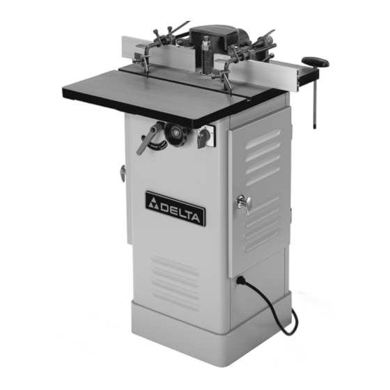
1 HP Professional
Wood Shaper
(Model 43-290C)
Part No. 1235200
Dated 8-30-01
Copyright © 2001 Delta Machinery
A Pentair Company
To learn more about DELTA MACHINERY
visit our website at: www.deltamachinery.com.
For Parts, Service, Warranty or other Assistance,
1-800-GO-DELTA (463-3582)
please call
Advertisement
Table of Contents

Related Manuals for Delta 43-290C


Summary of Contents for Delta 43-290C
- Page 1 1 HP Professional Wood Shaper (Model 43-290C) Part No. 1235200 Dated 8-30-01 Copyright © 2001 Delta Machinery A Pentair Company To learn more about DELTA MACHINERY visit our website at: www.deltamachinery.com. For Parts, Service, Warranty or other Assistance, 1-800-GO-DELTA (463-3582) please call...
-
Page 2: Table Of Contents
TABLE OF CONTENTS SAFETY INSTRUCTIONS ......... 3,4 UNPACKING MACHINE ..........4,5 ASSEMBLY INSTRUCTIONS Attaching Extensions Wing ........... 6 Attaching Adjusting Wrench and Bracket ......6 Assembling and Attaching Fence ......... 7 Assembling and Changing Spindles ........8 Stock Guide Assembly and Positioning ........ 9 ELECTRICAL CONNECTIONS Power Source .............. -
Page 3: Safety Instructions
DO NOT use the machine until equipment such as guards, push sticks, hold-downs, you have first contacted Delta to determine if it can or featherboards, goggles, dust masks and hearing protection should be performed on the product. -
Page 4: Unpacking Machine
UNPACKING THE MACHINE Carefully unpack the Delta Shaper and all loose items from the shipping containers. Check to see that you have all of the items listed in this manual. Do not turn the machine ON if any of these items are missing. You may cause injury to yourself and also damage the machine. - Page 5 Fig. 3 Figure 3 The following shaper parts require assembly. Please be sure all of the listed parts are included before starting assembly. 1. Center Guard and Dust Chute 10. Stock Guide Spring Bars (4) 2. 1/2” and 3/4” Spindles w/collars 11.
-
Page 6: Assembly Instructions
ASSEMBLY INSTRUCTIONS WARNING: FOR YOUR OWN SAFETY, DO NOT PLUG SHAPER IN OUTLET UNTIL THE TOOL IS COMPLETELY ASSEMBLED AND YOU READ AND UNDERSTAND THE ENTIRE INSTRUCTION MANUAL. Attaching Extension Wing to Shaper Table Figure 4 Using supplied hex head screws and washers (A), attach the extension wing (B) to shaper table. -
Page 7: Assembling And Attaching Fence
Assembling and Attaching Fence Figure 7 The fence for this shaper can be mounted in two positions. Forward, using the two front fence mount holes (A), or in the back using the two rear fence mount holes (B). Note: The two table inserts (C) have been removed to show the three insert leveling screws (D). -
Page 8: Assembling And Changing Spindles
Assembling and Changing Spindles DISCONNECT TOOL FROM POWER SOURCE. Figure 11 Thread the end of the tie rod with the shorter threads (A) into the spindle bottom (B). Insert tie rod and spindle into the spindle cartridge, making sure the notches in the spindle (C) engage with the pins (D) on the spindle cartridge. -
Page 9: Stock Guide Assembly And Positioning
Stock Guide Assembly and Positioning Figure 14 Slide two guide brackets (A) onto a guide assembly rod (B). Thread two allen lock screws(C) into threaded holes on guide brackets and hand tighten. Fig. 14 Figure 15 Insert stock guide rod (A) thru hole in fence bracket (B). Thread an allen lock screw (C) into top of fence bracket and tighten with adjusting hex wrench. -
Page 10: Electrical Connections
ELECTRICAL CONNECTIONS Power Source A seperate electrical circuit should be used for your tool. This circuit should not be less than #12 wire and should be protected with a 20 amp time lag fuse. Before connecting the motor to the power line, make sure the switch is in the “OFF” position and be sure the electric current is of the same characteristics as indicated on the tool. -
Page 11: Extension Cords
Extension Cords Make sure your extension cord is in good condition an is a 3-wire extension cord which has a 3-prong grounding type plug and matching receptacle which will accept the tool’s plug. When using an extension cord, be sure to use one heavy enough to carry the current of the tool. -
Page 12: Operating Controls And Adjustments
OPERATING CONTROLS AND ADJUSTMENTS Starting and Stopping the Shaper Reversing Spindle Rotation Raising and Lowering Spindle Locking Shaper Spindle Figure 22 To apply power to the machine, turn knob (A) to the right for forward operation, and to the left for reverse operation. Never attempt to reverse the rotation of the spindle while the motor is still running. -
Page 13: Fence Controls And Adjustments
Fence Controls and Adjustments DISCONNECT TOOL FROM POWER SOURCE. Figure 24 The fence halves (A) should be adjusted so that the opening at the spindle is no more than is required to clear the cutter. To adjust the fence halves, loosen indexable locking levers (B) and slide fence halves to the required position. -
Page 14: Operations
OPERATIONS Shaping When using the Fence as a Guide The use of the fence is the safest and most satisfactory method of shaping. Most straight work can be shaped using the fence described below. Figure 26 For average work, where a portion of the original edge of the work is not touched by the cutter, both the front and rear fences are in a straight line (Fig. -
Page 15: Accessories
ACCESSORIES A complete line of accessories is available form your Delta Supplier, Porter-Cable • Delta Factory Service Centers, and www.deltamachinery.com Delta Authorized Service Stations. Please visit our Web Site for a catalog or for the name of your nearest supplier. -
Page 16: Parts, Service And Warranty
PARTS, SERVICE, AND WARRANTY ASSISTANCE All Delta Machines and accessories are manufactured to high quality standards and are serviced by a network of Porter- Cable • Delta Factory Service Centers and Delta Authorized Service Stations. To obtain additional information regarding your Delta quality product or to obtain accessories, parts, service, warranty assistance, or the location of the nearest service outlet, please call 1-800-463-3582.
Need help?
Do you have a question about the 43-290C and is the answer not in the manual?
Questions and answers
Can you get a 1/2" adaptor for this wood shaper 43-290C modelto accomdate router bits