Table of Contents
Advertisement
Quick Links
To learn more about DELTA MACHINERY
visit our website at: www.deltamachinery.com.
For Parts, Service, Warranty or other Assistance,
1-800-223-7278 (
please call
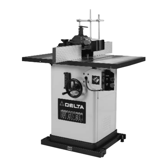
2-Speed Heavy-Duty
Wood Shaper
In Canada call
(Model 43-435)
(Model 43-455)
SHOWN WITH ACCESSORY
MOBILE BASE
PART NO. 432-02-651-0033 - 05-08-02
Copyright © 2002 Delta Machinery
1-800-463-3582).
Advertisement
Table of Contents

Related Manuals for Delta 43-435


Summary of Contents for Delta 43-435
- Page 1 (Model 43-455) SHOWN WITH ACCESSORY MOBILE BASE PART NO. 432-02-651-0033 - 05-08-02 Copyright © 2002 Delta Machinery To learn more about DELTA MACHINERY visit our website at: www.deltamachinery.com. For Parts, Service, Warranty or other Assistance, 1-800-223-7278 ( 1-800-463-3582). please call...
-
Page 2: General Safety Rules
If you have any questions rela- tive to a particular application, DO NOT use the machine until you have first contacted Delta to determine if it can or should be performed on the product. - Page 3 ADDITIONAL SAFETY RULES FOR WOOD SHAPERS WARNING: FAILURE TO FOLLOW THESE RULES MAY RESULT IN SERIOUS PERSONAL INJURY. 21. ONLY SHAPE LARGE WORKPIECES when using start- DO NOT OPERATE THIS MACHINE UNTIL it is assem- bled and installed according to the instructions. ing pin and collar(s).
-
Page 4: Power Connections
POWER CONNECTIONS Model 43-435 - A separate electrical circuit should be used for this machine. This circuit should not be less than #12 wire and should be protected with a 20 amp time lag fuse or motor-starting circuit breaker. If an extension cord is used, use only 3-wire extension cords which have 3-prong grounding type plugs and matching receptacle which will accept the tool’s... -
Page 5: Unpacking And Cleaning
FOREWORD Delta Model 43-435 (3 HP) and Model 43-455 (5 HP) are both single phase, 240V wood shaping machines. They utilize a Poly V- belt drive system that transmits more efficient torque to the spindle and have a capacity (under nut) of 5". -
Page 6: Carton Contents
CARTON CONTENTS Model 43-455 Model 43-435 4. 10" Wide Cast Iron Extension Wings (2) 4. 10" Wide Cast Iron Extension Wings 5. Wrenches (2) 5. Wrenches (2) 6. 7/16-20 x 1" Hex Head Screws (6) for mounting 6. 7/16-20 x 1" Hex Head Screws (6) for mounting... - Page 7 ASSEMBLY INSTRUCTIONS WARNING: FOR YOUR OWN SAFETY, DO NOT CONNECT THE TOOL TO THE POWER SOURCE UNTIL THE TOOL IS COMPLETELY ASSEMBLED, AND YOU READ AND UNDERSTAND THE ENTIRE INSTRUCTION MANUAL. ATTACHING SPINDLE RAISING AND LOWERING HANDWHEEL Insert key (A) Fig. 6 into slot in spindle raising and lowering shaft (B). Place the handwheel (C) Fig.
- Page 8 Fig. 11B Fig. 11 NOTE: Position the switch adapter plates (H) inside the shaper cabinet (Fig. 11). Attach the on/off switch (A) Fig. 9 to the switch mounting bracket (B) Fig. 11B, through the two holes (J). Use two #10-32 x 1/2"...
- Page 9 ATTACHING CUTTERS AND COLLARS TO SPINDLE Disconnect tool from power source. Three different-sized collars (A) Fig. 17A are supplied with the 43-435 shaper. These collars allow the cutter and/or the 4-1/2" diameter spindle guard to be positioned at various locations on the spindle.
-
Page 10: Operating Controls And Adjustments
ATTACHING SPINDLE GUARD A 4-1/2”spindle guard is supplied with the 43-435, while a 6-1/2" spindle is supplied with the 43-455. CAUTION: The diameter of the spindle guard should be at least 1" more than the maximum cutting circle of the shaper cutter and the height of the guard should not exceed 1/4"... -
Page 11: Changing Speeds And Adjusting Belt Tension
CHANGING SPEEDS AND ADJUSTING BELT TENSION The tool is supplied with a 2-step motor pulley and a 2-step spindle pulley that provide spindle speeds of 7,000 and 10,000 RPM. With the belt on the largest step of the motor pulley and the smallest step of the spindle pulley, the spindle speed will be 10,000 RPM. -
Page 12: Shaping With Collars And Starting Pin
The rear fence should then be advanced to contact the work (Fig. 30), putting it in line with the cutting circle SHAPING WITH COLLARS AND STARTING PIN When shaping with collars and starting pin, follow the rules Fig. 30 below for superior finishing and safety in operation. Free the collars of ALL gum or other substances, and make sure that they are smooth. -
Page 13: End Shaping
END SHAPING Maintain sufficient support of the workpiece during all shaping operations. When end shaping a workpiece that is not long enough to be sufficiently supported halfway through the cut, USE A MITER GAUGE OR BACK-UP BLOCK (Figs. 38 and 39). WARNING: Shaping a narrow workpiece without sufficient support could result in serious injury. -
Page 14: Replacing Spindle Cartridge
Cable · Delta Factory Service Centers and Delta Authorized Service Stations. To obtain additional information regard- ing your Delta quality product or to obtain parts, service, warranty assistance, or the location of the nearest service out- let, please call 1-800-223-7278 (In Canada call 1-800-463-3582). - Page 15 Two Year Limited Warranty Delta will repair or replace, at its expense and at its option, any Delta machine, machine part, or machine accessory which in normal use has proven to be defective in workmanship or material, provided that the customer returns the product pre- paid to a Delta factory service center or authorized service station with proof of purchase of the product within two years and provides Delta with reasonable opportunity to verify the alleged defect by inspection.
- Page 16 Parts and accessories for Porter-Cable ·Delta products should be obtained by contacting any Porter-Cable·Delta Distributor, Authorized Service Center, or Porter-Cable·Delta Factory Service Center. If you do not have access to any of these, call 800-223-7278 and you will be directed to the nearest Porter-Cable·Delta Factory Service Center. Las Estaciones de Servicio Autorizadas están ubicadas en muchas grandes ciudades.
Need help?
Do you have a question about the 43-435 and is the answer not in the manual?
Questions and answers