Table of Contents
Advertisement
Quick Links
Advertisement
Table of Contents

Related Manuals for JVC VN-C205


Summary of Contents for JVC VN-C205
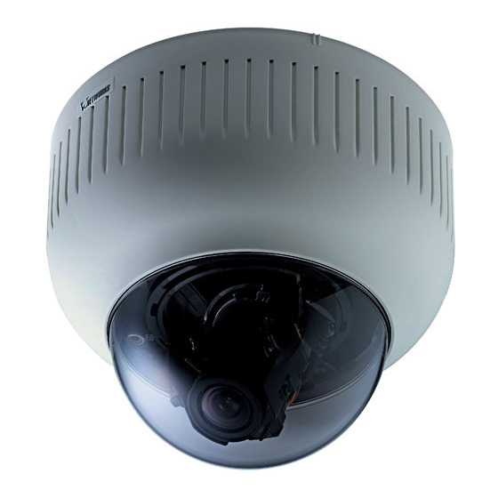
- Page 1 FIXED DOME NETWORK CAMERA INSTRUCTIONS VN-C205 For Customer Use: Enter below the Serial No. which is located on the body. Retain this information for future reference. Model No. VN-C205 Serial No. LWT0280-001A © 2005 Victor Company of Japan, Limited. LWT0280-001A...
-
Page 2: Important Safeguards
Cet appareil numérique de la Class A est This device complies with part 15 of the FCC Rules. conforme á la norme NMB-003 du Canada. Changes or modifications not approved by JVC could void the user’s authority to operate the equipment. WARNING (FOR EUROPE):... -
Page 3: Table Of Contents
Introduction Thank you for purchasing this product. (These instructions are for VN-C205U.) Before beginning to operate this unit, please read the instruction manual carefully in order to make sure that the best possible performance is obtained. Contents Contents ... 4 Introduction Characteristics ... -
Page 4: Introduction
This is not a malfunction. When shooting a bright object (eg. lamps, JVC will not be liable for any damage resulting etc.), white vertical streaks may appear on from the camera dropping due to incomplete the object on the screen. -
Page 5: Operating Environment
☞ Pages or items to refer to. * JVC shall not be held liable for any loss or damage to the customer or any claim from a third party arising from the use of this software. Specifications of this software are subject to alteration for improvement without prior notice. - Page 6 Introduction Name and Function of Parts (Continued) Body Surface View when the dome cover is removed. For instructions on removing the dome cover, see step 4 of “Mounting the Camera to the Ceiling”. ☞ page 17) Head MONITOR terminal (RCA pin) For adjusting the lens, focus, or camera angle.
-
Page 7: Connection Examples
C205U Setup Tool", and register the connected camera with the "V.Networks Controller". ● In a system where more than 1 VN-C205 is used, turn on the power for a VN-C205 first, followed by setting the camera until "2-3 Setting IP Address for this Camera Using the 'VN-C205U Setup Tool' "... -
Page 8: The Flowchart Of Installation Work For Camera
Preparation (Step 1 Connection/Installation) 1-1 The flowchart of installation work for camera Getting Started Caution Attachment of a embedded cover in the ceiling (recess bracket) may be mandatory in certain regions. If this is so, ensure that the embedded cover (recess bracket) is securely attached ☞... -
Page 9: Mounting The Camera To The Ceiling
● Please refer to the instruction manual for the cover in use for details on installation of the embedded cover (recess bracket). ● For more detail, please contact the JVC. Embedded Cover in Ceiling (recess bracket) 1. Preparations Open hole in ceiling, connect cables and mount camera to ceiling. -
Page 10: Connection To Alarm Input/Output Terminal
• Allowed input current: 50 mA • Momentary output: 1 to 5000ms (Set duration using the controller) Caution Connect the grounding terminal of VN-C205 to the GND terminal of the alarm device. Insert CF card in the direction as indicated in the diagram •... -
Page 11: Installation
Preparation (Step 1 Connection/Installation) 1-2 Mounting the Camera to the Ceiling (Continued) 2. Installation Attach the safety cable to the ceiling slab. (Safety cable not included) Attach to ceiling slab Attach the safety cable that has already been attached to the camera to the ceiling slab or Alarm signal cable channel. -
Page 12: Connection Of The Input Power Cable
Note Connecting multiple VN-C205 Cameras In a system where more than 1 VN-C205 is used, turn on the power for a VN-C205 first, followed by setting the camera until "2-3 Setting IP Address for this Camera Using the 'VN-C205U Setup Tool' "... -
Page 13: When Installing The Camera To The Electrical Box
Preparation (Step 1 Connection/Installation) 1-2 Mounting the Camera to the Ceiling (Continued) 3. Adjustment of the camera’s angle of view (Continued) ● Adjusting the focal length Turn the securing screw of the focal adjustment ring counterclockwise. Focal length Adjust the focal length. adjustment ring IRIS LEVEL Turn the securing screw clockwise to... -
Page 14: Pull Out The Cables Aside And Mount
[Programs] [V. NETWORKS] folder. Installing the VN-C205U Setup Tool 1. Execute "Setup.exe". This is located inside the [Setup] folder of the [JVC] folder. 2. Follow instructions on the screen to install the software. 3. If installation is successful, the [Programs] [V. -
Page 15: Setting Pc's Ip Address [Windows Xp]
Settings (Step 2 Network Settings) 2-2 Setting PC's IP Address [Windows XP] Upon installing the camera, set the IP address of the PC that is used to operate this camera. For Windows XP, set according to the following procedure. ☞ (For Windows 2000, Page 30) Note... -
Page 16: Setting Pc's Ip Address [Windows 2000]
Settings (Step 2 Network Settings) 2-2 Setting PC's IP Address [Windows 2000] Upon installing the camera, set the IP address of the PC that is used to operate this camera. For Windows 2000, set according to the following procedure. Click •... -
Page 17: Setting Ip Address For This Camera Using The "Vn-C205U Setup Tool
Page 56) Note In a system where more than 1 VN-C205 is used, turn on the power for a VN-C205 first, followed by setting the camera until "2-3 Setting IP Address for this Camera Using the 'VN-C205U Setup Tool' " is completed. Upon doing so, turn on a second camera and perform setting in the same way. -
Page 18: Other Settings Using The "Vn-C205U Setup Tool
• For a password-protected VN-C205, a password request screen will be displayed. • VN-C205 setup will not be possible unless the correct administrator password is entered. • Security level increases in the order from user to operator to administrator. Password protection will not be valid if a password is assigned only to a lower level but not to a higher one. -
Page 19: Multicast
• Set the multicast address within the range between 225.0.0.0 to 239.255.255.255. Do not set the same multicast address for different devices on the same system. • To view VN-C205 images in the multicast mode through a router, either the following operating environment or router setting will be required. - Page 20 Start up the "VN-C205U Setup Tool", select [Alarm Setting] and set [Motion Detection] ☞ to "Available". ( Page 44 "Other Trigger") Select [Motion Detect] under [VN-C205 Setup Tool]. Select "ON" to turn on the motion detection feature. For setting the time interval for defining a motion.
-
Page 21: Motion Detection Setting
Settings (Step 2 Network Settings) 2-4 Other Settings Using the "VN-C205U Setup Tool" (4. Alarm Setting) This section describes procedures for alarm setting. Alarm Input • When there is an input of signals to the alarm input terminal on the ceiling mount. ☞... - Page 22 Settings (Step 2 Network Settings) 2-4 Other Settings Using the "VN-C205U Setup Tool" (4. Alarm Setting) (Continued) Alarm Input Item Function/Set Value Alarm 1/Alarm 2 This section describes setting procedures for alarm input. Mode For selecting whether to enable or disable the input signals. Set Values : Available, Not Available Detect Mode For selecting the method for detecting input signals.
-
Page 23: Recording Setting
Settings (Step 2 Network Settings) 2-4 Other Settings Using the "VN-C205U Setup Tool" (4. Alarm Setting) (Continued) Other Triggers Item Function/Set Value Motion Detection For setting alarm operations when motion is detected within the area specified in the motion detection settings. •... -
Page 24: Recording Files
[Before trigger] and [After trigger] values cannot be set to "0" at the same time. ● Due to the memory capacity of VN-C205, recording time set for [Before trigger] and [After trigger] may differ from the actual maximum recording time. -
Page 25: Web
Settings (Step 2 Network Settings) 2-4 Other Settings Using the "VN-C205U Setup Tool" (6. Web) A designated html file can be set as the default page for the web browser using this setting. Start up the "VN-C205U Setup Tool" and select [Web]. Specify settings for viewing using the web browser. -
Page 26: Time Setting
Settings (Step 2 Network Settings) 2-4 Other Settings Using the "VN-C205U Setup Tool" (8. FTP Client Setting) VN-C205 is equipped with a "FTP Client" feature that uploads still images to the existing FTP server on a regular interval. This feature enables simultaneous image monitoring by many clients (from many locations). - Page 27 Settings (Step 2 Network Settings) 2-4 Other Settings Using the "VN-C205U Setup Tool" (9. Time Setting) This section describes how to set the standard time for VN-C205. NTP can also be used for this function. Start up the "VN-C205U Setup Tool" and select [Time].
-
Page 28: Registering Connected Camera Using The "V.networks Controller
● Images are divided into IP fragments when set to "High Speed". ● Images will be sent at the frame rate set at VN-C205. When setting the frame rate to "High Speed", do so upon ensuring that this does not impose excessive burden on the network. ( ●... -
Page 29: Step 3 Setting Using The V.networks Controller
● Enter the correct password if a password has been set. ● This controller can be connected to VN-C1, VN-C2, VN-C3, VN-C30 (JPEG only), VN-A1, VN-C10 (JPEG and MPEG), VN-C655 and VN-C625 as well VN-C205. 3-2 Features that Allow Setting Using the V.Networks Controller The V.Networks Controller can be used to perform settings for image size and alarm. -
Page 30: Motion Detection Standby
Settings (Step 3 Setting Using the V.Networks Controller) 3-3 Motion Detection Standby The "Motion Detection Standby" function enables automatic connection upon receiving notifications on detected motion from VN-C205 when the V.Networks Controller has been started up. Select [File] and [Motion Detection Standby]. -
Page 31: Image Quality Setting
Frame rate for local recording cannot be set using this function. To set the frame rate for local recording, make use of the "VN-C205U Setup Tool" ( Set the maximum number of images per second that are sent from VN-C205. (Factory Setting: 15) Set value : 30, 15, 10, 8, 6, 5, 4, 3, 2, 1,1/ 2,1/3, 1/5, 1/10, 1/15, 1/20, 1/30 ☞... -
Page 32: Alarm Setting
Settings (Step 3 Setting Using the V.Networks Controller) 3-7 Alarm Setting The "V.Networks Controller" can be used to set the action to be taken when an alarm signal is received. Select [Setting] and [Alarm Setting]. Change the set values. (For description of each function, Setting may be performed for the [Motion Detection], [Alarm 1], [Alarm 2], [Relay Alarm]. -
Page 33: Time Stamp
Settings (Step 3 Setting Using the V.Networks Controller) 3-8 Time Stamp The "V.Networks Controller" can be used to set the time stamp that displays date/ time on camera images. The displayed time/date will be recorded. Select [Setting] and [Time Stamp]. 2.Perform setting. -
Page 34: Features That Allow Operation Using The V.networks Controller
The "V.Networks Controller" can be used to select a camera as well as record/play back camera images. (The controller screen is identical to other V.Networks versions, and there are functions that cannot be operated from VN-C205) 2 3 4 5 CAMERA Snap Shot Displays the name of the connected camera. -
Page 35: Playback
Operations (Step 4 Operation Using the V.Networks Controller) 4-3 Playback Files saved upon "REC" using the "V.Networks Controller" can be selected and played back. (Playback of a file and display of motion images cannot be performed at the same time.) Click the [PLAY] button. -
Page 36: Cautions On Record/Play Functions
The [Save As] screen is displayed. Note Other Viewer Software ● Still image files that are saved using VN-C205 can also be displayed on other conventional viewer software. However, inverted images will not be reversed. In addition, the color reproduced may also differ. -
Page 37: Operating Environment
Access linking by host name will be possible as long as the environment allows use of a DNS (Domain Name System). ● It is possible to establish a 1-to-1 connection between the PC and VN-C205 using a crossover cable. (Although rare, the use of crossover cables may not be possible with some LAN boards. -
Page 38: Other Settings
Operations (Step 5 Operating Using a Web Browser) 5-3 Starting Up the Web Browser Specify the default web page address of VN-C205 as the page to view using the web browser. (Upon entering the factory setting of the IP address, the web browser will display the front page of VN-C205.) -
Page 39: Other Settings
* The FTP user name is fixed as "Administrator". Use the Administrator Level Password as the FTP password. Usually, the top page of VN-C205 is specified. When this function is availabled, the specified html file will be used as the default page. -
Page 40: View Setting
(users) that are connected. The access protection function is divided into 3 levels according to the authorization levels. Pages that can be accessed (browsed) for each authorization level are as follows. (Refer to Page 73 for the configuration of web pages in VN-C205.) Authorization Level... -
Page 41: Alarm Setting
Operations (Step 5 Operating Using a Web Browser) 5-4 Setting Using the Web Browser (3. Alarm Setting) Alarm Setting window: http://******/alarm-e.html ("******" represents the URL of VN-C205) This page describes procedures for setting VN-C205 operation upon input of alarm signals. Click set values. Click the set values. -
Page 42: Ftp Setting
Note ● What is an FTP Client? It is a feature that uploads VN-C205 images (still images) to the existing FTP server at a regular interval. By doing so, it is possible to make use of the server's image distribution services, thereby enabling distribution of images to a considerably larger number of clients. -
Page 43: Viewing Still Images
5-5 Viewing Still Images Still Image Page: http:// ****** /still-e.html (" ****** " represents the URL of VN-C205) This page can only be used to view still images. Camera image at the point when browsing starts is displayed. To update the image, use [Refresh] or [Reload] on the web browser. To save the displayed image, use [Save As] on the web browser. -
Page 44: Image Link
● If a password has been set, password authentication will be necessary before display of motion images using Java is made possible. (This is an Internet Explorer restriction.) ● Ensure that the "WIDTH" and "HEIGHT" values are identical to the image size set in VN-C205. Others... -
Page 45: Others Troubleshooting
Others Troubleshooting (Continued) Symptom Causes/Remedial Actions ● Live images may appear in slow motion or loss of frames Video images cannot be displayed may occur when the PC specifications or network smoothly. bandwidth is inadequate. ● Repair services will be required to undo the password Forgotten the password upon protection feature.
Need help?
Do you have a question about the VN-C205 and is the answer not in the manual?
Questions and answers