Table of Contents
Advertisement
www.workoutwarehouse.com
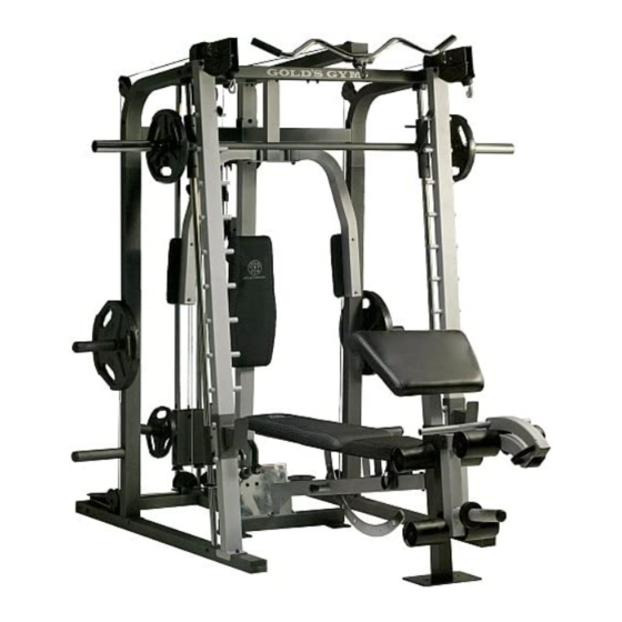
Model No. GGBE6958.1
Serial No.
Write the serial number in the
space above for reference.
Serial Number Decal (under seat)
QUESTIONS?
If you have questions, or if parts are
damaged or missing, DO NOT
CONTACT THE STORE; please
contact Customer Care.
IMPORTANT: Please register this
product (see the limited warranty
on the back cover of this manual)
before contacting Customer Care.
1-877-776-4777
CALL TOLL-FREE:
Mon.–Fri. 6 a.m.–6 p.m. MT
Sat. 8 a.m.–4 p.m. MT
ON THE WEB:
www.workoutwarehouse.com
CAUTION
Read all precautions and instruc-
tions in this manual before using
this equipment. Keep this manual
for future reference.
USERʼS MANUAL
Advertisement
Table of Contents

Related Manuals for Gold's Gym Platinum GGBE6958.1


Summary of Contents for Gold's Gym Platinum GGBE6958.1
- Page 1 USERʼS MANUAL Model No. GGBE6958.1 Serial No. Write the serial number in the space above for reference. Serial Number Decal (under seat) QUESTIONS? If you have questions, or if parts are damaged or missing, DO NOT CONTACT THE STORE; please contact Customer Care.
- Page 2 Apply the decal in the location shown. Note: The decal(s) may not be shown at actual size. GOLD'S GYM is a registered trademark of Gold's Gym International, Inc. This product is manufactured and distributed under license from Gold's Gym Merchandising, Inc.
-
Page 3: Important Precautions
IMPORTANT PRECAUTIONS WARNING: To reduce the risk of serious injury, read all important precautions and instructions in this manual and all warnings on your weight bench before using your weight bench. ICON assumes no responsibility for personal injury or property damage sustained by or through the use of this product. -
Page 4: Before You Begin
BEFORE YOU BEGIN Thank you for selecting the versatile GOLDʼS GYM reading this manual, please see the front cover of this ® PLATINUM weight bench. The weight bench offers a manual. To help us assist you, note the product model selection of weight stations designed to develop every number and serial number before contacting us. -
Page 5: Part Identification Chart
PART IDENTIFICATION CHART Refer to the drawings below to identify small parts used in assembly. The number in parentheses by each draw- ing is the key number of the part, from the PART LIST near the end of this manual. Note: If a part is not in the hardware kit, check to see if it has been preattached. - Page 6 M8 x 76mm Carriage Bolt (143) M10 x 67mm Button Bolt (90) M6 x 67mm Screw (89) M10 x 76mm Button Bolt (102) M10 x 65mm Carriage Bolt (83) M6 x 80mm Screw (87) 3/8" x 3" Hex Bolt (105) M10 x 62mm Button Bolt (88) M10 x 82mm Button Bolt (106) M10 x 53mm Button Bolt (147)
- Page 7 ASSEMBLY To make assembly easier, carefully read the • For help identifying small parts, use the PART following assembly tips: IDENTIFICATION CHART on pages 5 and 6. • To hire an authorized service technician to • The included grease and the following tools (not assemble the weight bench in your home, call included) may be required for assembly: 1-800-445-2480.
- Page 8 2. Insert two M10 x 65mm Carriage Bolts (83) up through the Center Base (2). Place tape over the bolt heads to hold them in place. 3. Attach a Base (1) to the Center Base (2) with two M10 x 93mm Button Bolts (97), an M10 Split Washer (93), two M10 Washers (84), and an M10 Locknut (79).
- Page 9 5. Attach the Left Support (6) to the left Base (1) with the indicated two M10 x 65mm Carriage Hole Bolts (83) and two M10 Locknuts (79). Do not tighten the Locknuts yet. Repeat this step with the Right Support (7). 6.
- Page 10 7. Attach an Upright Cap (34) to the Left Upright (3) with two M4 x 16mm Screws (82). Attach the Left Upright (3) to the left Base (1) with the indicated two M10 x 65mm Carriage Bolts (83) and two M10 Locknuts (79). Do not tighten the Locknuts yet.
- Page 11 9. Orient the Left Spotter (24) as shown. Slide the Left Spotter and two Carriage Bumpers (27) onto the left Weight Bar Guide (5). Then, engage the Left Spotter onto the Left Upright (3). Repeat this step with the Right Spotter (not shown) and the right Weight Bar Guide (not shown).
- Page 12 12. Insert a Guide Cap (33) upward into a Side Top Frame (13). Set the Side Top Frame on the left Weight Bar Guide (5) and insert it into the Left Support (6). Attach the Side Top Frame (13) to the Left Upright (3) and the Left Support (6) with two M10 x 76mm Button Bolts (102), two M10 x 25mm Button Screws (98), four M10 Split...
- Page 13 15. Attach a Support Frame (15) to the left Side Top Frame (13) with two M10 x 93mm Button Bolts (97), two M10 Washers (84), and two M10 Locknuts (79). Do not tighten the Locknuts yet. Attach the other Support Frame (15) to the right Side Top Frame (13) in the same way.
- Page 14 18. Attach the Top Frame (16) to the Center Top Frame (14) with two M10 x 116mm Button Bolts (101), four M10 Washers (84), and two M10 Locknuts (79). Do not tighten the Locknuts yet. 19. Attach the Top Frame (16) to the Carriage Guides (64) with two M10 x 93mm Button Bolts (97), four M10 Washers (84), four 25mm Spacers (55), and two M10 Locknuts (79).
- Page 15 21. Attach the Foot Plate (9) to the Center Base (2) and the Backrest Upright (8) with four M10 x 19mm Button Bolts (77) and four M10 Locknuts (79). See steps 3–8, 12, 14–16, and 18–20. Tighten all of the Bolts, Screws, and Locknuts. 22.
- Page 16 24. Route the Butterfly Cable (71) under a 90mm Pulley (58). Attach the 90mm Pulley and two Half Guards (40) to the Double U-bracket (46) with an M10 x 46mm Button Bolt (96) and an M10 Locknut (79). 25. Route the Butterfly Cable (71) over a V-pulley (60).
- Page 17 27. Locate the High Cable (73). Route the High Cable upward through the Top Frame (16) and over a 90mm Pulley (58). Attach the 90mm Pulley inside the Top Frame with an M10 x 93mm Button Bolt (97), two M10 Washers (84), two 25mm Spacers (55), and an M10 Locknut (79).
- Page 18 30. Wrap the High Cable (73) over a 90mm Pulley (58) and over the indicated rod in the Top Frame (16). Attach the 90mm Pulley to the Top Frame with an M10 x 46mm Button Bolt (96) and an M10 Locknut (79). 31.
- Page 19 34. Route the Low Cable (72) over a 90mm Pulley (58). Attach the 90mm Pulley and two Half Guards (40) to the Double U-bracket (46) with an M10 x 46mm Button Bolt (96) and an M10 Locknut (79). 35. Route the Low Cable (72) under a 90mm Pulley (58).
- Page 20 38. Wrap the Low Cable (72) over a 90mm Pulley (58). Attach the 90mm Pulley to the Top Frame (16) with an M10 x 46mm Button Bolt (96) and an M10 Locknut (79). 39. Attach the Low Cable (72) to the U-bracket (47) with an M6 Washer (86) and an M6 Locknut (80).
- Page 21 41. Route the Long Cable (54) over a 90mm Pulley (58). Attach the 90mm Pulley and a Small Cable Trap (63) to the left Side Top Frame (13) with an M10 x 49mm Button Bolt (104) and an M10 Locknut (79). Make sure that the Small Cable Trap is oriented to hold the Long Cable in the groove of the 90mm Pulley.
- Page 22 45. Route the Long Cable (54) over a 90mm Pulley (58). Attach the 90mm Pulley, a Small Cable Trap (63), and two Half Guards (40) to the lower hole of the U-bracket (47) with an M10 x 53mm Button Bolt (147) and an M10 Locknut (79). Make sure that the Cable Trap is oriented to hold the Long Cable in the groove of the Pulley.
- Page 23 49. Route the Long Cable (54) over a 90mm Pulley (58). Attach the 90mm Pulley and a Small Cable Trap (63) to the right Side Top Frame (13) with an M10 x 49mm Button Bolt (104) and an M10 Locknut (79). Make sure that the Small Cable Trap is oriented to hold the Long Cable in the groove of the 90mm Pulley.
- Page 24 53. Attach an Arm Pad (30) to the Right Arm (11) with two M6 x 80mm Screws (87) and two M6 Washers (86). Attach the other Arm Pad (30) to the Left Arm (10) in the same way. 54. Slide a Weight Bumper (37) onto each storage tube on the Left Support (6).
- Page 25 56. Attach two Plastic Foot Plates (50) to the Bench Stabilizer (108) with four M4 x 10mm Screws (95). 57. Attach the Bench Stabilizer (108) to the Bench Frame (107) with two M8 x 76mm Carriage Bolts (143) and two M8 Locknuts (78). Do not tighten the Locknuts yet.
- Page 26 60. Orient the two Backrest Frames (118) with the indicated holes nearer the bottom. Attach the Holes Backrest Frames to the Backrest Bracket (111) with four M8 x 42mm Hex Bolts (130), four M8 Washers (94), and four M8 Locknuts (78). Do not tighten the Locknuts yet.
- Page 27 63. Pull the Bench Knob (124) outward and insert the Backrest Bracket (111) through the Bench Frame (107). Engage the Bench Knob into the Backrest Bracket. 64. Apply grease to an M10 x 180mm Button Bolt (145). Attach the Backrest Frames (118) and the Seat Bracket (121) to the Bench Frame (107) with the Button Bolt, two M10 Washers (84), and an M10 Locknut (79).
-
Page 28: Adjustment
66. Insert a Pad Tube (129) through the Leg Lever (110). Slide a Foam Pad (128) onto each end of the Pad Tube. Attach the other Pad Tube (129) in the same way. Attach the Long Pad Tube (115) to the Front Leg (109) in the same way. -
Page 29: Exercise Guidelines
ADJUSTMENT This section explains how to adjust the weight bench. See the EXERCISE GUIDELINES on page 35 for impor- tant information about how to get the most benefit from your exercise program. Also, refer to the accompanying exercise guide to see the correct form for several exercises. ATTACHING ACCESSORIES To use a Handle (67), attach the Handle to the Clip (53) on the end of any cable. - Page 30 USING THE WEIGHT BAR To use the Weight Bar (17), first place the desired amount of weight (not included) onto the ends of the Weight Bar (see ADDING WEIGHT below). Then, disengage the Locking Bar (18) by rotating it off the Uprights (3, 4). When finished with the exercise, reengage the Locking Bar (18) by rotating it onto the Uprights (3, ADDING WEIGHT...
- Page 31 ADJUSTING THE SEAT Hold the Seat (116) with one hand and disengage the Seat Pin (123) from the Seat Frame (122). Move the Seat to the desired position and reengage the Seat Pin into the Seat Frame and the Bench Frame (107).
-
Page 32: Cable Diagrams
CABLE DIAGRAMS The diagram below shows the proper routing of the cables. The numbers in each drawing show the proper rout- ing for that cable. Use the diagram to make sure that the cables, cable traps, and guards are assembled correctly. - Page 33 High Cable (73) Length: 13 ft. 6 in. (4.11 m) Low Cable (72) Length: 23 ft. 11 in. (7.29 m)
- Page 34 MAINTENANCE Make sure that all parts are properly tightened each time the weight bench is used. Replace any worn parts immediately. The weight bench can be cleaned with a damp cloth and mild, non-abrasive detergent; do not use solvents. TIGHTENING THE CABLES Woven cable, the type of cable used on the weight bench, can stretch slightly when it is first used.
-
Page 35: Exercise Guidelines
EXERCISE GUIDELINES FOUR TYPES OF STRENGTH WORKOUTS workout, and the numbers of repetitions and sets to complete. Progress at your own pace and be sensitive Note: A “repetition” is one complete cycle of an exer- to your bodyʼs signals. Follow each workout with at cise, such as one sit-up. - Page 36 EXERCISE LOG Make copies of this page, and use the copies to schedule and record your strength and aerobic workouts. Scheduling and recording your workouts will help you to make exercise a regular and enjoyable part of your life. Strength Exercise Lbs.
- Page 37 NOTES...
- Page 38 PART LIST—Model No. GGBE6958.1 R0810A Key No. Qty. Description Key No. Qty. Description Base Large Foot Plate Center Base Cable Stop Left Upright Clip Right Upright Long Cable Weight Bar Guide 25mm Spacer Left Support Bearing Right Support Swivel Axle...
- Page 39 Key No. Qty. Description Key No. Qty. Description M10 x 116mm Button Bolt Foam Pad M10 x 76mm Button Bolt Pad Tube Large Full Guard M8 x 42mm Hex Bolt M10 x 49mm Button Bolt 64mm Thin Square Cap 3/8" x 3" Hex Bolt 64mm Thick Square Cap M10 x 82mm Button Bolt 50mm Square Cap...
- Page 40 EXPLODED DRAWING A—Model No. GGBE6958.1 R0810A 130 146 120 121...
- Page 41 EXPLODED DRAWING B—Model No. GGBE6958.1 R0810A...
- Page 42 EXPLODED DRAWING C—Model No. GGBE6958.1 R0810A 56 57 84 79 79 40...
- Page 43 EXPLODED DRAWING D—Model No. GGBE6958.1 R0810A 33 66 58 75 63 40 58 63...
-
Page 44: Part List
ORDERING REPLACEMENT PARTS To order replacement parts, please see the front cover of this manual. To help us assist you, be prepared to provide the following information when contacting us: • the model number and serial number of the product (see the front cover of this manual) •...
Need help?
Do you have a question about the Platinum GGBE6958.1 and is the answer not in the manual?
Questions and answers