Advertisement
Table of Contents
®
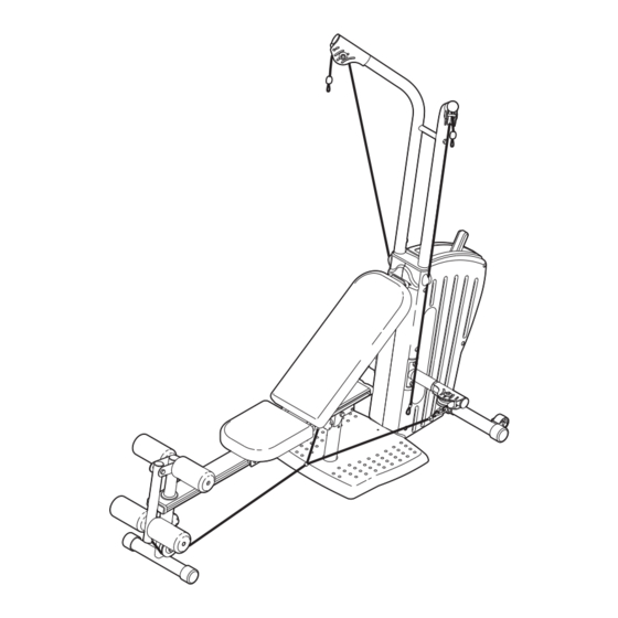
Model No. GGSY2921.0
Serial No.
Write the serial number in the
space above for reference.
Serial
Number
Decal
QUESTIONS?
As a manufacturer, we are com-
mitted to providing complete
customer satisfaction. If you
have questions, or if a part is
damaged or missing, PLEASE
CONTACT OUR CUSTOMER
SERVICE DEPARTMENT
DIRECTLY.
CALL TOLL-FREE:
1-877-776-4777
Mon.–Fri., 6 a.m.–6 p.m. MST
ON THE WEB:
www.goldsgympowerflex.com
CAUTION
Read all precautions and instruc-
tions in this manual before using
this equipment. Save this manual
for future reference.
USER'S MANUAL
Advertisement
Table of Contents

Subscribe to Our Youtube Channel
Related Manuals for Gold's Gym GGSY2921.0


Summary of Contents for Gold's Gym GGSY2921.0
- Page 1 ® Model No. GGSY2921.0 Serial No. Write the serial number in the space above for reference. Serial Number Decal QUESTIONS? As a manufacturer, we are com- mitted to providing complete customer satisfaction. If you have questions, or if a part is...
-
Page 2: Table Of Contents
Note: a PART LIST/EXPLODED DRAWING is attached in the center of this manual. Remove the PART LIST/EXPLODED DRAWING before beginning assembly. GOLD'S GYM is a registered trademark of Gold's Gym International, Inc. This product is manufactured and distributed under license from Gold's Gym International, Inc. -
Page 3: Important Precautions
WARNING : To reduce the risk of serious injury, read the following important precautions before using the resistance system. 1. Read all instructions in this manual and in the accompanying literature, and all warn- ings on the resistance system before using the resistance system. -
Page 4: Before You Begin
Bench Frame and serial number before calling. The model number is ® GGSY2921.0. The serial number can be found on a decal attached to the resistance system (see the front cover of this manual). To avoid a registration fee for any service needed under warranty, you must register the resistance system at www.goldsgympowerflex.com/registra-... -
Page 5: Part Identification Chart
Refer to the drawings below to identify small parts used in assembly. The number in paren- theses by each drawing is the key number of the part, from the PART LIST in the center of this manual. Note: Some small parts may have been pre-attached. If a part is not in the parts bag, check to see if it has been pre-attached. -
Page 6: Assembly
Make Things Easier for Yourself This manual is designed to ensure that the resistance system can be assembled success- fully by anyone. Most people find that by setting aside plenty of time, assembly will go smoothly. Before beginning assembly, carefully read the following information and instructions: •... - Page 7 with two M10 x 25mm Button Screws (83) and two M10 Split Washers (70). Note: Make sure that the grip tape is on top. Attach the Right Arm (not shown) in the same manner. 4. Orient the Upright Stabilizer (7) as shown. Attach the Upright Stabilizer to the Upright Base (6) with two M8 x 70mm Carriage Bolts (76) and two M8 Black Nylon Locknuts (71).
- Page 8 6. Press two 57.1mm Round Outer Caps (59) onto the ends of the Front Leg (1). Pull the Seat Knob (36) out as far as it will go and remove the Seat Frame (19) from the Bench Frame (2) and set it aside. Orient the Bench Frame (2) as shown.
- Page 9 9. Lubricate an M10 x 83mm Bolt (92). Attach the Pivot Bracket (23) to the Base (4) with the Bolt, an M10 Nylon Locknut (72), and a Bench Knob (41). 10. Press two 2” Round Inner Caps (56) into the top and bottom of the Leg Developer (21).
- Page 10 12. Slide the Backrest Frame (17) into the slot in the Seat Frame (19). Rest the Backrest Frame against the Upright Base (6). 13 Wrap a Medium Nylon Rope (52) around a “V”- Pulley (49) with the ball on the side shown. Note: Be sure the ball is on the correct end of the Rope;...
-
Page 11: Adjustments
ADJUSTMENTS The instructions below describe how each part of the resistance system can be adjusted. Refer to the exercise guide accompanying this manual to see how the resistance system should be set up for each exercise. IMPOR- TANT: When attaching the leg press strap, ankle strap, or handles, make sure that the accessories are in the correct starting position for the exercise to be performed. -
Page 12: Adjusting The Backrest
ADJUSTING THE LEG DEVELOPER To adjust the height of the Leg Developer (21), unscrew the Bench Knob (41) from the Front Leg (1). Align the hole in the Leg Developer with one of the three holes in the Front Leg. Retighten the Knob into the Front Leg and Leg Developer. -
Page 13: Adjusting The Seat
ADJUSTING THE SEAT To allow the Seat (20) to roll up and down the Bench Frame (2), remove the backrest from the Seat Frame (see REMOVING THE BACKREST on page 12). Pull the Seat Knob (36) out as far as it will go, and turn the Knob so that the pin rests at the end of the “L”- slot (see the inset drawing). - Page 14 To store the resistance system, secure the Seat Knob (36) into the adjustment hole in the Bench Frame (2) that is closest to the Leg Developer (21) (see ADJUSTING THE BACKREST on page 12). Remove the indicated Bench Knob (41) from the Base (4) and lift the Leg Developer so that it rests against the Left and Right Uprights (8, 9).
- Page 15 Key No. Qty. Description Front Leg Bench Frame Base Stabilizer Base Base Cover Upright Base Upright Stabilizer Left Upright Right Upright Left Cover Right Cover Left Arm Right Arm Pulley Arm Resistance Bracket Resistance Leg Backrest Frame Backrest Seat Frame Seat Leg Developer Leg Lever...
- Page 16 EXPLODED DRAWING—Model No. GGSY2921.0 R1005A...
-
Page 17: Ordering Replacement Parts
To order replacement parts, see the front cover of this manual. To help us assist you, please be prepared to give the following information: 1. the MODEL NUMBER of the product (GGSY2921.0) 2. the NAME of the product (GOLD’S GYM POWER FLEX resistance system) 3.
Need help?
Do you have a question about the GGSY2921.0 and is the answer not in the manual?
Questions and answers