
Related Manuals for KTI Networks KSD-541


Summary of Contents for KTI Networks KSD-541
-
Page 1: Installation Guide
Industrial 5-Port Fast Ethernet Switches with SFP Slot and optional 4 PoE PSE Ports Basic Model: KSD-541 PoE Model: KSD-541-P Installation Guide DOC.100125... - Page 2 KTI Networks Inc. KTI Networks Inc. reserves the right to revise this documentation and to make changes in content from time to time without obligation on the part of KTI Networks Inc. to provide notification of such revision or change.
- Page 3 The information contained in this document is subject to change without prior notice. Copyright (C). All Rights Reserved. TRADEMARKS Ethernet is a registered trademark of Xerox Corp. WARNING: This equipment has been tested and found to comply with the limits for a Class A digital device, pursuant to Part 15 of the FCC Rules.
-
Page 4: Table Of Contents
Table of Contents 1. Introduction ....................5 1.1 Features ........................6 1.2 Product Panels ......................6 1.3 LED Indicators ......................6 1.4 Specifications ......................7 2. Installation ....................9 2.1 Unpacking .........................9 2.2 Safety Cautions ......................9 2.3 Mounting the Switch on a Wall................... 9 2.4 Din-Rail Mounting .................... -
Page 5: Introduction
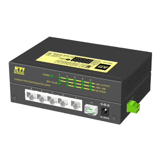
1. Introduction The switches are 5-port Fast Ethernet switches which are featured with four copper ports and one combo port. The combo port comes with one RJ-45 and one SFP slot. The SFP slot can be mounted with a fiber transceiver optionally to support a fiber connection. For more coming PoE (Power Over Ethernet) applications, the PoE switch model is equipped with PoE design in four copper ports. -
Page 6: Features
1.1 Features Provides 5 10/100Mbps RJ-45 and one 100Mbps SFP slot All copper ports support auto-negotiation and auto-MDI/MDI-X detection Provides full wire speed forwarding Supports IEEE 802.3x flow control for full-duplex and backpressure for half-duplex Provides SFP slot for optional optical fiber connection Provides four IEEE 802.3af-compliant PoE PSE ports Provides two types of power supply interfaces - DC Jack and terminal block Supports stand-alone, wall, Din-Rail, and panel mounting... -
Page 7: Specifications
1.4 Specifications Copper Ports w/h PSE (P2-P5) Compliance IEEE 802.3 10Base-T, IEEE 802.3u 100Base-TX Connectors Shielded RJ-45 jacks Pin assignments Auto MDI/MDI-X detection Configuration Auto-negotiation Transmission rate 10Mbps, 100Mbps Duplex support Full/Half duplex Network cable Cat.5 UTP Power over Ethernet IEEE 802.3af-compliant PSE (function equipped in PoE Model only) Combo Port (P1) Compliance... - Page 8 Power over Ethernet Function (PoE Model) PSE Pin 4,5 Positive of power voltage (Typical 48VDC) PSE Pin 7,8 Negative of power voltage (Typical 48VDC) Discovery PD resistance 15K ~ 33K PD Classification Class 0 ~ 4 Power delivery 15.4W max. (per port) Protection Under voltage protection Over voltage protection...
-
Page 9: Installation
2. Installation 2.1 Unpacking The product package contains: • The switch unit • One product CD-ROM 2.2 Safety Cautions To reduce the risk of bodily injury, electrical shock, fire, and damage to the product, observe the following precautions. • Do not service any product except as explained in your system documentation. •... -
Page 10: Din-Rail Mounting
2.4 Din-Rail Mounting The steps to mount the switch on a Din-rail are: One Din-rail mounting bracket is provided in the product package as shown below: Install the bracket on the bottom of the switch unit. Mount the device on a Din-rail. -10-... -
Page 11: Panel Mounting
2.5 Panel Mounting One optional panel mounting bracket is available for purchase as shown below: Install the bracket on the bottom of the switch unit. The final dimension after panel bracket is installed is shown below: 2.6 Applying Power The switch provides two types of power interfaces, terminal block and DC power jack for receiving DC power input from external power supply system. - Page 12 Using Terminal Blocks Three terminal contacts are provided: Vdc Positive ( ) terminal Vdc Negative ( ) terminal Chassis ground * Working Vdc for general application: +6V ~ +60VDC * Working Vdc for PoE application : +43V ~ +54VDC (Typ. 48V) One 3P terminal plugs are provided together with the switch.
-
Page 13: Making Connections
3. Making Connections 3.1 Making UTP Connections The copper ports support the following connection types and distances: Network Cables 10BASE-T: 2-pair UTP Cat. 3,4,5 , EIA/TIA-568B 100-ohm 100BASE-TX: 2-pair / 4-pair UTP Cat. 5, EIA/TIA-568B 100-ohm Link distance: Up to 100 meters Auto MDI/MDI-X Function This function allows the port to auto-detect the twisted-pair signals and adapts itself to form a valid MDI to MDI-X connection with the remote connected device automatically. -
Page 14: Making Poe Connections
3.3 Making PoE Connections This section describes how to make a connection between a PSE port and a PoE PD device. For the PoE switch model, Port 2, Port 3, Port 4 and Port 5 are equipped with PoE PSE function. The ports are enabled to deliver power together with network signal to a connected powered device via Cat.5 cable. -
Page 15: Led Indication
3.4 LED Indication Function State Interpretation POWER Power status The power is supplied to the switch. The power is not supplied to the switch. LINK/ACT Port link status A port link is established. (No traffic) BLINK Port link is up and there is traffic. Port link is down. -
Page 16: Applications
4. Applications 4.1 Applications with Basic Switch Model The following figure illustrates a basic switch model connects five computers via Cat.5 cables. The following figure illustrates a basic switch model connects four computers via Cat.5 cables and uplink to a fiber backbone network. -16-... -
Page 17: Applications With Poe Switch Model
4.2 Applications with PoE Switch Model The figure below illustrates a PoE switch connects four PoE IP cameras via Cat.5 cables and uplinks to a fiber backbone: The figure below illustrates a PoE switch connects four PoE WLAN access points via Cat.5 cables and uplinks to a backbone: -17-... - Page 18 The figure below illustrates a PoE switch powered by a 48V DC power adapter connects four PoE media converters via Cat.5 cables and uplinks to a fiber backbone: -18-...
Need help?
Do you have a question about the KSD-541 and is the answer not in the manual?
Questions and answers