Table of Contents
Advertisement
Quick Links
Introduction.........................................2
Supply Voltage Considerations...........................2
Location Considerations..................................3
Section 2: Mounting.............................4
Marine Magellan...........................................4
Artion GSM Module.........................................5
Artion Battery Backup....................................5
Section 3: Electrical Installation............7
AC Installations...........................................7
DC Installations............................................9
Communication Lines....................................9
1 - Language............................................12
2 - User Profile..........................................12
3 - Communicator......................................14
4 - Delays and Tones.................................17
5 - System Test.........................................17
6 - Zone Profile: Overview............................18
Zone Definitions.............................18
Zone Hardware Descriptions............20
Installation Manual
Marine Magellan 6130/6160
Table of Content
6 - Zone Profile: Programming.......................25
7 - Output Profile: Overview.........................27
7 - Output Profile: Programming...................29
8 - Keypad Profile Overview.........................31
8 - Keypad Profile Programming....................33
9 - Repeater Profile Overview.......................33
9 - Repeater Profile Programming..................33
10 - Signal Strength.....................................34
11 - Passwords..........................................34
Console Trouble.........................................35
AC Diagram..............................................37
DC Diagram..............................................38
PGM Wiring Examples...........................39 -42
Programming web.......................................43
Marine Magellan Keypad Description................4
DCTXP2.......................................20
PMD-75 Motion Detector..................22
SD-738 Smoke Detector..................23
Battery Low Voltage Detector............23
High Water Alarm...........................25
PGM Activation Events ...................27
PGM Electrical Installation...............29
1
Advertisement
Table of Contents

Related Manuals for Paradox Marine Magel 6130


Summary of Contents for Paradox Marine Magel 6130
-
Page 1: Table Of Contents
Installation Manual Marine Magellan 6130/6160 Table of Content Introduction………………………………..2 DCTXP2…………………..…….……...20 PMD-75 Motion Detector……………...22 Section 1: Installation Consideration…...2 SD-738 Smoke Detector………………23 Supply Voltage Considerations......2 Battery Low Voltage Detector………...23 Location Considerations…….…………....3 High Water Alarm……………………...25 Section 2: Mounting………………………..4 6 - Zone Profile: Programming…………...……..25 Marine Magellan……………………………..4 7 –... -
Page 2: Introduction
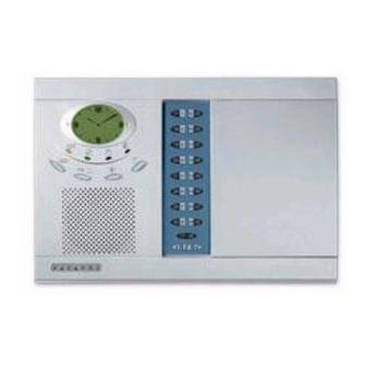
Introduction Congratulations on your purchase of the Marine Magellan wireless security and monitoring system for your yacht (Diagram 1). The system is designed to provide reliable protection giving you true piece of mind when you are away from your vessel. This guide is designed to walk the installer through the complete setup and basic wireless programming of the Marine Magellan System. -
Page 3: Section 1: Installation Consideration
Section 1: Installation Consideration AC installation The placement of the individual There must be a constant 110 VAC components of the Marine Magellan system source in the vicinity of the units for power. is very important. The installer must make The 16 VAC transformer must plug into the sure that adequate security concerns and 110 VAC outlet. -
Page 4: Section 2: Mounting
There must be an adequate wire run Applicable) according to the criteria on the behind the Marine Magellan, Artion, and previous pages, it is time to mount them. the Artion Battery Backup Case (if Marine Magellan applicable) so wiring is not exposed. The Marine Magellan uses a plastic wall Exposed wires compromise the systems plate for wall mounting (Diagram 2). -
Page 5: Artion Gsm Module
plate. This will secure the console to the wall. Artion GSM Module It is important that the GSM communication module be mounted in such a location to allow accessibility without obvious visibility. Follow the steps below. 1.) Establish a proper location 2.) Mark the necessary holes to mount the Artion and allow wiring access. - Page 6 Diagram 4 Diagram 5...
-
Page 7: Section 3: Electrical Installation
into an existing outlet to get power, make Section 3: Electrical Installation sure that the existing breaker is properly * Power should be denied when current rated for the additional outlet. In making all electrical connections. either case, the AC breaker must be left on Only apply power when all wire while away from boat. - Page 8 Diagram 6 Diagram 7...
-
Page 9: Dc Installations
DC power Setup Artion GSM Module The Artion GSM module simply needs a Marine Magellan constant 12 VDC to operate The Marine Magellan panel can easily (Diagram 10). In AC installations this power be powered from the vessels 12VDC comes from the battery backup case. In DC system. - Page 10 Diagram 8 Diagram 9...
- Page 11 Diagram 10 Diagram 11 Diagram 12...
-
Page 12: Section 4: Programming
Magellan. The complete layout of the process that will require the use of the programming menus can be referenced on Paradox UIP-256 and a laptop computer. Appendage 7. The installer may wish to Contact Paradox Marine for language install the zones (wireless sensors) and upgrades on your panel. -
Page 13: System Master Code
for a total 16 maximum remotes on the system. In this section you have the ability to change user passwords, user voice labels, and add/delete remotes. System Master Code 2. Select which user you wish to add/modify With the System Master code a user can by pressing “next”. -
Page 14: Communicator
label is the person who will be using that 3 – Communicator password. (Examples: captain, first mate, In this section you will assign the various owner, etc.) call-out telephone numbers for the various recipients. Upon receiving the call, the user will hear the prerecorded voice label of the boat name and the condition that exists. - Page 15 4.) Continue in this fashion until all the recipients have been entered and it prompts you to “Record Alarm Mes?” 1.) From the “Voice Report” menu Press “ok”. 5.) Once you press “ok” you will be prompted to record an alarm message 2.) From the “Add Tel.
-
Page 16: Utility Reporting
disarms your system thus informing you that he is aboard. 9.) From the “Communicator” menu System troubles: Use this report type to Press “ok”. have the Marine Magellan console call you when specific troubles occur. After entering Utility Reporting the menu, select the desired trouble(s) you Utility reporting is an option that sends out a wish to be notified about. -
Page 17: Delays And Tones
all zones (except 24 Hr zones) in the 4 – Delays and Tones system. This menu allows you to set entry / exit times as well as associated sounds for the Bell Cutoff Delay – This is the amount of Marine Magellan. -
Page 18: Zone Profile: Overview
Entry Delay 1 6 - Zone Profile Typical position: Primary entry Description When the system is armed and a zone Zones are defined as the assorted defined with Entry Delay 1 opens, the wireless sensors that transmit open/close console will generate an alarm after the conditions to the Marine Magellan. - Page 19 Delay zone opens, the console will wait until • All zones defined as Instant/Stay zones the Entry Delay become Instant Timer of the zone that opened first has zones when the Marine Magellan system is elapsed. This feature is commonly used Regular armed.
-
Page 20: Zone Hardware Descriptions
Power: 2 x “AAA” Zone Hardware Descriptions Description: This device can be installed in This section loosely describes the basic another fashion utilizing is its universal operation of the assorted zones for the inputs. These two input terminals accept a system. - Page 21 Jumpers Normally Open Reed Switch/Universal Input: open = “zone open” signal closed = “zone closed” signal JP1 ON Normally Closed Reed Switch/Universal Input: open = “zone closed” signal closed = “zone open” signal JP1 OFF Not Used Diagram 15 Table 1 Mounting Learn Mode It is suggested that you first apply the...
-
Page 22: Pmd-75 Motion Detector
Diagram 16 2. Insert the battery holder into the back PMD-75 Motion Detector cover and affix the battery connector to the Typical Position: Salon, Stateroom, and PCB (see “A1” and “A2” in Figure Hallway Mounting Typical Zone Definition: Follow or Follow / It is recommended that the motion detector Stay be mounted high up on the wall or corner of... -
Page 23: Sd-738 Smoke Detector
into position. This will activate the motion Powering the Unit detector’s walk-test mode for 3 minutes. Open up the back cover of the unit to access the 9 volt battery. There is a plastic wrap Learn Mode around the battery that needs to be Power up the unit and allow the LED to removed. - Page 24 more than 2 minutes. The Low voltage It is important that the battery bank that you sensor is mounted in a sealed, waterproof, are monitoring is the same one that powers plastic enclosure. Typically it is hooked up your bilge pumps. This is the most vital to the primary domestic battery bank for the bank to monitor when away from your boat.
-
Page 25: High Water Alarm
Diagram 20 bilge. Typically the switch is mounted 6 to 8 High Water Alarm inches from the bilge bottom. The best Typical Position: Bilge Areas reference to mount it is about a half inch Typical Zone Definition: 24 Hour Buzzer below the level of the boat manufacturers Power: 2 x “AAA”... - Page 26 just makes more sense that having the zones randomly placed. 4.) This is where you say the name of the particular zone that you just learned into the panel. (ex. Saloon door, Forward High Water, etc.) 1.) Select Zone Profile by pressing “ok” 5.) Vocalize the zone label and press “stop”...
-
Page 27: Output Profile: Overview
can have the PGM toggle on and off from this button or even have timing cycle of 1, 5, 15, or 30 Seconds/minutes. This event is also a secondary toggle on/off option with every single PGM event. This comes in 8.) To add another zone to the next handy if you want to be able to have the available location and repeat the process... - Page 28 Follow Alarm this are interior lights that may come on Description: The PGM will activate for the when a certain door zone opens up. entire duration while in alarm. The only way to deactivate the PGM is by disarming the Follow arm system via key pad, key fob, or...
-
Page 29: Pgm Electrical Installation
PGM Electrical Installation basic specifications for the devices are in Table 3. When utilizing the two hardwired Before beginning the PGM electrical PGMs, the basic rule is to always trigger a installation to control a device it is important higher current relay to switch your device. to understand the power specifications and Reference Appendages 3 –... - Page 30 5.) Now 3.) If utilizing a “2WPGM” press “yes” and you must give the PGM a voice label to continue to the next step. If utilizing a identify the device that it is controlling. hardwired “PGM 1” or “PGM 2” (Output 1 Select “yes”.
-
Page 31: Keypad Profile Overview
battery, console message waiting and FM Radio activation (Diagram 21) Powering the Keypad Installing the Backup Battery 8.) Now you will be prompted to program the With the back plate removed, install the PGM to trigger on/off with the remote as a 3.7Vdc Li-ion rechargeable backup battery secondary activation event. - Page 32 Diagram 21 Diagram 22...
-
Page 33: Keypad Profile Programming
Diagram 23 Keypad Profile Programming 3.) Hold down “PGM 1” and “BYP” on the MG-32WK. This will learn the keypad to the system. 1.) To add a keypad press “ok” 9 – Repeater Profile A repeater is a device that will take in the Marine Magellan’s wireless signals and amplify them to the extremities of your vessel. -
Page 34: Signal Strength
MG-RPT1 per system. The Wireless Repeater also provides one PGM and one zone input with two-way wireless communication with the panel. The Repeater module is powered by the Select standard transformer (110 VAC to 16 VAC, “ok” for Repeater 1 and then press learn Diagram 24) switch on the powered repeater (Diagram 10 –... -
Page 35: Console Trouble
“NEXT” and press “OK” when the desired password appears. The following passwords can be programmed: Technical Support - Installer code Paradox Marine Technical Support - Maintenance code Toll Free: 866-929-4441 - Panel ID support@paradox-marine.com - PC Password... - Page 36 Table 2...
-
Page 37: Ac Diagram
Appendage 1 AC Installation... -
Page 38: Dc Diagram
Appendage 2 DC Installation... -
Page 39: Pgm Wiring Examples
Appendage 3 Hardwired PGM 1 Relay setup... - Page 40 Appendage 4 Hardwired PGM 2 Relay Setup...
- Page 41 Appendage 5 2WPGM Wiring setup (switching load below 5 amps)
- Page 42 Appendage 6 2WPGM Wiring setup (switching load above 5 amps)
-
Page 43: Programming Web
Appendage 7 Programming Web... - Page 44 Appendage 8 Marine Magellan Buttons...
Need help?
Do you have a question about the Marine Magel 6130 and is the answer not in the manual?
Questions and answers