Table of Contents
Advertisement
Quick Links
Advertisement
Table of Contents

Subscribe to Our Youtube Channel
Related Manuals for Paradox MG5000+


Summary of Contents for Paradox MG5000+
- Page 1 MG5000+ / MG5050+ Installation Guide 32-Zone Wireless Security Systems DRAFT...
-
Page 3: Table Of Contents
Table of Contents Introduction ............... 5 Switch to Stay Arming if no Entry Delay is opened ..........32 When Delay Zone is bypassed Follow Zones become Entry Delay 2 .... 32 Features ...........................5 Regular Arming switches to Force Arming ............. 32 MG5050+ Requirements ....................5 Stay Arming switches to Stay Force Arming ............ - Page 4 Limitations of Alarm Systems device, pursuant to Part 15 of the FCC Rules. These limits are designed to provide It must be understood that while your Paradox alarm system is highly advanced and secure, reasonable protection against harmful interference in a residential installation.
-
Page 5: Introduction
MG5000+ / MG5050+ Installation Guide Introduction Features • 32 zones (any of which can be wireless or keypad zones) • 32 users and 32 remote controls (one per user) • In-field upgradeable • Menu-driven programming for the Installer, Master, and Maintenance codes. This enables you to program the panel through a simple and easy to use interface, without the use of section numbers •... -
Page 6: Specifications
MG5000+ / MG5050+ Installation Guide Specifications MG5000+ / MG5050+ Power rating 16.5 VAC (50 or 60Hz) minimum 20 VA (40 VA recommended) Power consumption MG5000+: 1.2A(Max.), 85 mA (Idle) MG5050+: 1.2A(Max.), 95 mA (Idle) Aux. power * 0.7A typical, 0.8A maximum, active shutdown at 1.1A Battery 12 VDC, 4 Ah/7Ah Battery charging current... -
Page 7: Installation
MG5000+ / MG5050+ Installation Guide Installation Location and Mounting Before mounting the metal box, push the five white nylon mounting studs into the back of the box. Pull all cables into the cabinet and prepare them for connection before mounting the circuit board into the back of the cabinet. Select a centralized installation site on the main floor that isn't easily accessible to intruders and leave at least 5 cm (2 in.) around the panel box to permit adequate ventilation and heat dissipation. -
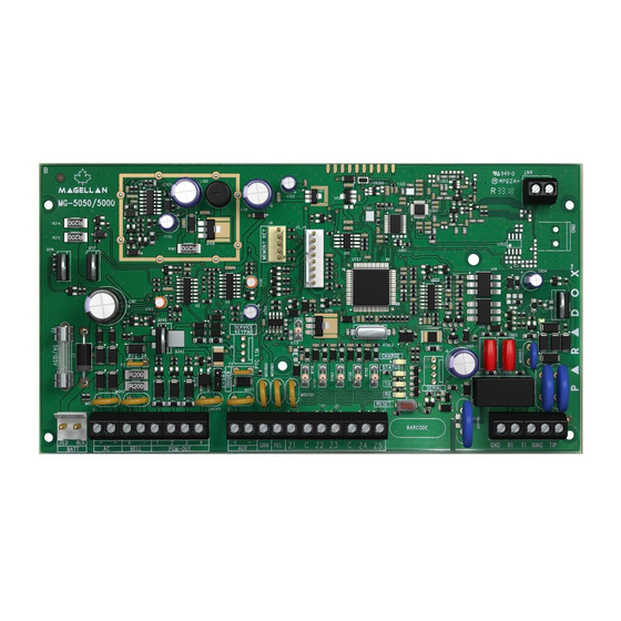
Page 8: Mg5000+ Pcb Layout
MG5000+ / MG5050+ Installation Guide MG5000+ PCB Layout Do not cut, bend, or alter the antenna, and ensure that electrical wires or other type of wires do not cross over it, as this may affect signal reception. Do not install the antenna near wires as it may cause interference. -
Page 9: Mg5050+ Pcb Layout
MG5000+ / MG5050+ Installation Guide MG5050+ PCB Layout Do not cut, bend, or alter the antenna, and ensure that electrical wires or other type of wires do not cross over it, as this may affect signal reception. Do not install the antenna near wires as it may cause interference. -
Page 10: Pcb Metal Box Installation
PCB Metal Box Installation The crosses and dotted line represent the PCB mounting location. If you need specific dimensions, contact Paradox Distributor Support. For UL recommended installation for the MG5000+ only, place the PCB one notch lower than the mounting location. -
Page 11: Auxiliary Power Terminals
Information security is achieved by 256 bit encrypted, supervised communication (AES validation number is 986) which prevents unauthorized reading or modification of messages. Paradox alarm reporting systems are compatible with a variety of report code formats that are detailed in the Programming Guide. Bell Output Connection The BELL+ and BELL- terminals power bells, sirens and other warning devices requiring a steady voltage output during an alarm. -
Page 12: Single Zone Inputs
MG5000+ / MG5050+ Installation Guide Single Zone Inputs Detection devices such as motion detectors and door contacts are connected to the control panel's zone input terminals. Figure 3 demonstrates single zone input terminal connections recognized by the panel. Once connected, the associated zone's parameters must be defined. Figure 3: Single Zone Input Connections... -
Page 13: Advanced Technology Zone (Atz) Connections
MG5000+ / MG5050+ Installation Guide Advanced Technology Zone (ATZ) Connections The ATZ feature is a software oriented feature that enables two detection devices to be installed per hardwired input terminal. Each detection device has its own zone, displays its zone status on the keypad and sends its own alarm codes. Fire zones cannot be doubled. Figure 4: Advanced Technology Zone Connections... -
Page 14: Fire Circuits
MG5000+ / MG5050+ Installation Guide Fire Circuits When a zone is programmed as a fire zone, the zone becomes normally open and requires an EOL resistor. If a line short occurs or if the smoke detector becomes active, whether the system is armed or disarmed, the control panel will generate an alarm. If a trouble occurs on a fire zone, the Fire Loop Trouble will appear in the keypad’s trouble display (see “Trouble Display”... -
Page 15: Programming Methods
Program the control panels remotely or on-site using the BabyWare Software (V2.80 or higher) for Windows®. For more information, contact your local Paradox Distributor or visit our web site at paradox.com. If you are using the BabyWare software, you must program the features (see “Settings for BabyWare Software” on page 49). -
Page 16: Configuring The Keypad Zone Number
MG5000+ / MG5050+ Installation Guide Configuring the Keypad Zone Number How Do I Configure The Keypad? Press [ ENTER Enter your [ ] (default: 0000 / 000000) or [ ] (empty by default) INSTALLER CODE MAINTENANCE CODE Press [ ] and hold for three seconds Enter the desired zone number key (K32+,K32LCD+: 2-digit entry 01 to 32, K10V/H: 1-digit entry 1 to 0(10)) Press [ ] to save and exit programming mode... -
Page 17: Lcd Keypad Labels
MG5000+ / MG5050+ Installation Guide LCD Keypad Labels Input Keys Special Function Keys Alphanumeric Key Input Function A / B / C Insert space [stay] D / E / F Delete [sleep] G / H / I Delete whole entry [arm] J / K / L Toggle numeric/alphanumeric keys... - Page 18 MG5000+ / MG5050+ Installation Guide Hebrew Keypad Letter Assignment Hebrew Special Characters Catalogue Greek Keypad Letter Assignment Greek Special Characters Catalogue Press key Press key Press key once twice three times A069...
- Page 19 MG5000+ / MG5050+ Installation Guide Russian Keypad Letter Assignment Russian Special Characters Catalogue...
-
Page 20: Access Codes
MG5000+ / MG5050+ Installation Guide Access Codes The control panel supports the following access codes: Installer Code [397]: Used to program all control panel settings except user access codes. The Maintenance code is similar to the Installer code. It can be used to enter programming mode, which allows you to pro- Maintenance Code [398]: gram all the features, options and commands except for the panel’s communication settings. -
Page 21: Lock Master Code
MG5000+ / MG5050+ Installation Guide Partition 2 Assignment Sections [404] to [432]: User Codes 004 to 032 Option [2] OFF= Deny access to partition 2 (default) Option [2] ON= User code has access to partition 2 If the system is partitioned (see “Partitioning” on page 46), user codes with this option enabled can arm and disarm partition 2. If the system is not partitioned, the control panel ignores this option. -
Page 22: Stayd Mode
MG5000+ / MG5050+ Installation Guide StayD Mode Overview • NOTE: StayD is automatically enabled when a path is programmed to a keypad. When deleting a wireless keypad from the system, the corresponding path zones will also be deleted. StayD simplifies your life and makes it safer by protecting you 24 hours a day, 7 days a week without ever having to disarm the system - even when entering an armed area. -
Page 23: Zone Programming
MG5000+ / MG5050+ Installation Guide Zone Programming When programming zones, the zone assignments are dependent on the designation of the wireless transmitters, assignment of keypad zones, and the detection devices that are connected to the panel. For keypad assignment, see “Configuring the Keypad Zone Number” on page 16. After assigning the required zones, you must set the zone’s definitions, partition assignment, and options see Figure 7 below. - Page 24 MG5000+ / MG5050+ Installation Guide Entry Delay 2 (Full Arm) Zones Sections [001] to [032]: Zones 1 to 32, First Digits = 04 Upon regular arming, the zone is Entry Delay 2 (see “Entry Delay 2 Zones” on page 23). Upon Stay/Sleep arming, the zone is bypassed by the system. See Zone Definition Status on page 26 for any exceptions.
- Page 25 MG5000+ / MG5050+ Installation Guide Delayed Fire Zones Sections [001] to [032]: Zones 1 to 32, First Digits = 12 When a Delayed 24Hr. Fire zone opens, whether it is armed or disarmed, the control panel will react as Figure 9: Delayed 24Hr Fire Zone shown in Figure 9.
-
Page 26: Zone Definition Status
MG5000+ / MG5050+ Installation Guide 24 Hr. Freeze Zones Sections [001] to [032]: Zones 1 to 32, First Digits = 21 When a 24Hr. Freeze zone opens, whether it is armed or disarmed, the control panel will immediately generate an alarm. This alarm is defined by the alarm type, configured in Zone Programming under zone options [4] and [5]. - Page 27 MG5000+ / MG5050+ Installation Guide Auto Zone Shutdown Sections [001] to [032] = Zones 1 to 32 Option [1] OFF= Auto Zone Shutdown Disabled Option [1] ON= Auto Zone Shutdown Enabled for selected zone (default) If, in a single armed period, the number of alarms generated by a zone with the Auto Zone Shutdown option enabled exceeds the number defined by the Auto Zone Shutdown Counter, the control panel will no longer generate an alarm for that zone.
-
Page 28: Eol Zones
MG5000+ / MG5050+ Installation Guide Force Zones Sections [001] to [032]: Zones 1 to 32 Option [8] OFF= Force Zone Disabled Option [8] ON= Selected Zone is Force Enabled (default) Any open Force Zones at the time of arming will be considered deactivated by the control panel. If during this period a deactivated zone is closed, the control panel will revert that zone to active status. -
Page 29: Keyswitch Programming
MG5000+ / MG5050+ Installation Guide Keyswitch Programming Keyswitch Numbering On-board hardwire control panel zones only. Keyswitch Numbering allows you to assign any hardwired input in the system to any of the 32 keyswitch zones in the control panel. Keyswitch Definitions Keyswitch Definitions determine how a keyswitch is used. -
Page 30: Wireless Features
MG5000+ / MG5050+ Installation Guide Wireless Features For information on how to configure wireless modules, please refer to the appropriate module’s installation guide for details. Please note that configuration for the wireless modules can only be done via a TM50/TM70 keypad. Supervision Options The Supervision Options cannot be used with any remote controls assigned to the control panel. - Page 31 MG5000+ / MG5050+ Installation Guide Programming the Remote Control Buttons Sections [611] to [642]: Remote Controls 1 to 32 respectively. Each remote control can be programmed to perform up to 4 different actions. Each digit in sections [611] to [642] represents a button or combination of buttons. Digits 1 through 4 can be programmed, while digits 5 through 8 are reserved for future use and must be defined as empty (reminder: [SLEEP] = empty).
-
Page 32: Switch To Stay Arming If No Entry Delay Is Opened
MG5000+ / MG5050+ Installation Guide Arming and Disarming Options Switch to Stay Arming if no Entry Delay is opened Section [741]: Partition 1, Section [742] = Partition 2 Option [5] OFF= Switch to Stay Arming Disabled (default) Option [5] ON= Switch to Stay Arming Enabled If a user Regular arms a partition, but does not exit through (open and close) an entry delay zone during the exit delay, the control panel can be programmed to switch from Regular arming to Stay arming. -
Page 33: Restrict Arming On Wireless Supervision Trouble
MG5000+ / MG5050+ Installation Guide Restrict Arming on Wireless Supervision Trouble Section [703]: Arming/Disarming Options Option [7] OFF= Permit arming on wireless supervision failure (default) Option [7] ON= Restrict arming on wireless supervision failure If this option is enabled, the control panel will not arm the system if the control panel detects a wireless supervision trouble on one or more zones. The control panel will not arm the system until all wireless supervision trouble conditions are rectified. -
Page 34: One-Touch Arming
MG5000+ / MG5050+ Installation Guide One-Touch Arming Section [703]: Options [1] to [3] Option [1] ON = Press & hold the key for One-touch Regular Arming. Option [2] ON = Press & hold the key for One-touch Stay Arming. STAY Option [3] ON = Press &... -
Page 35: Alarm Options
MG5000+ / MG5050+ Installation Guide Alarm Options Bell Cut-Off Timer Section [747] = Partition 1, [748] = Partition 2 000 = Disabled, 001 to 255 minutes, Default = 4 minutes After an audible alarm, the bell or siren will stop upon disarming of the partition or when the Bell Cut-Off Timer has elapsed, whichever comes first. Recycle Alarm After the Bell Cut-Off Timer and the Recycle Delay have elapsed, the control panel will re-verify the zone status. -
Page 36: Tamper Supervision On Panel
MG5000+ / MG5050+ Installation Guide Tamper Supervision on Panel Section [700]: Supervision Options Option [8] OFF= Panel tamper supervision disabled Option [8] ON= Panel tamper supervision enabled (default) When the control panel detects a tamper, the control panel can generate an alarm or trouble, unless the Tamper Supervision is disabled. Keypad Panic Options Section [702]: General Options Option [1] OFF= Panic 1 Disabled (default) -
Page 37: Reporting And Dialer Settings
MG5000+ / MG5050+ Installation Guide Reporting and Dialer settings The following section explains all the features and options that must be programmed in order for your security system to properly report system events to a monitoring station. When an event (e.g. zone in alarm) occurs in the system, the control panel verifies if a report code was programmed in the section corresponding to the event (except Ademco Contact ID “All Codes”). -
Page 38: System Trouble Report Codes
MG5000+ / MG5050+ Installation Guide System Trouble Report Codes Section [865] to [869] When the system generates one of the instances listed below, the control panel can send the appropriate report code to the monitoring station identifying the type of system trouble. Section [865] •... -
Page 39: Clear Reporting Codes
MG5000+ / MG5050+ Installation Guide Clear Reporting Codes Section [966]: Clear Reporting Codes Option [1] OFF= Clear zone reporting codes Option [1] ON= Clear zone reporting codes (default) Option [2] OFF= Clear user reporting codes Option [2] ON= Clear user reporting codes (default) Option [3] OFF= Clear arm/disarm/alarm reporting codes Option [3] ON= Clear arm/disarm/alarm reporting codes (default) Option [4] OFF= Clear trouble reporting codes... -
Page 40: Reporting Formats
MG5000+ / MG5050+ Installation Guide Reporting Formats Section [810]: 1st digit = Format for Phone #1, 2nd digit = Format for Phone #2 The panel can use a number of different reporting formats and each monitoring station telephone number can be programmed with a different reporting format. The first digit entered into section [810] represents the reporting format used to communicate with Monitoring Station Telephone Number 1, the second digit represents the reporting format used to communicate with Monitoring Station Telephone Number 2. -
Page 41: Dialing Method
MG5000+ / MG5050+ Installation Guide Example: The system is armed and zone 1 has been breached causing an alarm. If options [5] and [7] are OFF and option [6] is ON in section [802], the control panel will attempt to communicate with MSTN 2. Account Numbers Section [811]: Partition 1, Section [812]: Partition 2 All report codes are preceded by a 4-digit or 3-digit Partition Account Number to ensure correct identification in a partitioned system. -
Page 42: Recent Closing Delay
MG5000+ / MG5050+ Installation Guide Recent Closing Delay Section [838] 000 = Disabled, 001 to 255 seconds, Default = Disabled If after having armed the system, an alarm is generated within the period defined by the Recent Close Delay, the control panel will attempt to transmit the Recent Close report code programmed in section [863]. -
Page 43: Zone Restore Report Options
MG5000+ / MG5050+ Installation Guide Zone Restore Report Options Section [801]: Zone Options Option [2] OFF= Report On Bell Cut-Off (default) Option [2] ON= Report On Zone Closure With option [2] OFF, the panel will send the Zone Alarm Restore report codes to the monitoring station when the zone has returned to normal and the Bell Cut-Off Timer has elapsed. -
Page 44: Programmable Outputs
MG5000+ / MG5050+ Installation Guide Programmable Outputs PGM is a programmable output that toggles to its opposite state (e.g., a normally open PGM will close) when a specific event has occurred in the system. For example, a PGM can be used to activate bells or strobe lights, open/close garage doors and much more. When a PGM activates, the control panel triggers any device or relay connected to it. -
Page 45: Pgm Programming
MG5000+ / MG5050+ Installation Guide When armed, the PGM will pulse once every 30 seconds. Option [6] OFF= PGM Pulse on any alarm disabled (default) Option [6] ON= PGM Pulse on any alarm enabled This option sets the PGMs to pulse on any alarm. Option [7] OFF= PGM Pulse on any alarm Partition 1(default) Option [7] ON= PGM Pulse on any alarm Partition 2 Program PGMs to pulse during an alarm for either partition. -
Page 46: System Settings
MG5000+ / MG5050+ Installation Guide System Settings Version Number Display Enter section [980] to view the version number of the panel. The first digit will appear. Press [ ] to scroll through each consecutive digit (the keypad will beep ENTER twice after every digit in the version number). -
Page 47: Daylight Savings Time
MG5000+ / MG5050+ Installation Guide ] = Test Report: Send the “Test Report” report code programmed in section [875] to the monitoring station. ENTER INSTALLER CODE ] = Cancel Communication: Cancels all communication with BabyWare software or with the monitoring station until the next ENTER INSTALLER CODE STAY... -
Page 48: Display Exit Delay On Lcd Keypad (K32Lcd+)
MG5000+ / MG5050+ Installation Guide Option [7] OFF= Display entry delay on LCD keypad Option [7] ON= Display entry delay on LCD keypad (default) When this option is enabled the panel will display entry delays on the K32LCD+ keypad modules. Display Exit Delay on LCD keypad (K32LCD+) Section [701]: General System Options Option [8] OFF= Display exit delay on LCD keypad... -
Page 49: Settings For Babyware Software
MG5000+ / MG5050+ Installation Guide Settings for BabyWare Software Panel Answer Options The following two options define how the control panel answers an incoming call from a computer using the BabyWare Software for Windows®. Answering Machine Override Delay Section [902] 000 = Disabled, 000 to 255 seconds, Default = 030 When using the BabyWare software to communicate with an installation site that uses an answering machine or service, the answering machine override must be programmed. -
Page 50: Automatic Event Buffer Transmission
MG5000+ / MG5050+ Installation Guide Automatic Event Buffer Transmission Section [900]: Dialer Options Option [2] OFF= Auto Event Buffer Transmission Disabled (default) Option [2] ON= Auto Event Buffer Transmission Enabled When the event buffer reaches 90% capacity, the control panel will make two attempts to establish communication with a PC using the BabyWare software by [915] calling the PC Telephone Number programmed in section . -
Page 51: User Operation
MG5000+ / MG5050+ Installation Guide User Operation Alarm Display If an alarm has occurred on a zone, the respective zone LED will flash, the [ ] key will light up, and the zones will be stored in memory. These respective LEDs will continue to flash until disarming even if the zones are restored. -
Page 52: Index
MG5000+ / MG5050+ Installation Guide INDEX Numerics With Remote Control ....................33 Bypassable Zones ........................26 101 ..............................39 24 Hr. Burglary Zones ......................24 24 Hr. Buzzer ..........................24 24 Hr. Freeze Zones ........................ 25 Call Back Feature ........................49 24 Hr. - Page 53 MG5000+ / MG5050+ Installation Guide Follow / Stay Zones ........................ 23 On Battery Fail ......................31 Follow No Pre-Alarm ......................25 On Tamper Trouble ..................... 31, 32 Follow Zones ..........................23 No Audible Feedback Upon Stay Arming ..............33 Force ............................40 No Exit Delay When Arming with Remote Control ............
- Page 54 MG5000+ / MG5050+ Installation Guide Programming Remote Control Buttons .............. 30 Trouble Restore Codes ..................36, 37 Remote Disarm Report Code ....................36 Repetition ..........................42 Report ............................41 Tamper Bypass Options ....................... 34 Report Code, Special Tamper Recognition ......................34 Cold Start ........................
- Page 55 The whole Paradox team wishes you a successful and easy installation. We hope this product performs to your complete satisfaction. Should you have any questions or comments, please contact us at support@paradox.com. Additional information can be found on our website www.paradox.com/support...
Need help?
Do you have a question about the MG5000+ and is the answer not in the manual?
Questions and answers