Table of Contents
Advertisement
Quick Links
Advertisement
Table of Contents

Summary of Contents for Toro TMR-1
-
Page 2: Table Of Contents
T T a a b b l l e e o o f f C C o o n n t t e e n n t t s s P P a a g g e e T T M M R R - - 1 1 R R e e m m o o t t e e C C o o n n t t r r o o l l S S y y s s t t e e m m O O v v e e r r v v i i e e w w ..1 H H a a n n d d h h e e l l d d T T r r a a n n s s m m i i t t t t e e r r C C o o m m p p o o n n e e n n t t s s . -
Page 3: T T M M R R - - 1 1 R R E E M M O O T T E E C C O O N N T T R R O O L L S S Y Y S S T T E E M M O O V V E E R R V V I I E E W W
NiMH batteries and compatible charger. A pre-wired, quick-release receiver mount enables the TMR-1 system to be quickly installed and ready for opera- tion; then easily moved from site to site as needed. The TMR-1 system is designed for simple “plug and play”... -
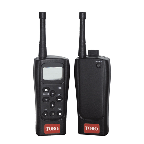
Page 4: H H A A N N D D H H E E L L D D T T R R A A N N S S M M I I T T T T E E R R C C O O M M P P O O N N E E N N T T S S
H H a a n n d d h h e e l l d d T T r r a a n n s s m m i i t t t t e e r r C C o o m m p p o o n n e e n n t t s s 1 1 - - A A n n t t e e n n n n a a - - Screw-mount, flexible whip. - Page 5 T T M M R R - - 1 1 T T r r a a n n s s m m i i t t t t e e r r C C o o m m p p o o n n e e n n t t s s...
-
Page 6: R R E E C C E E I I V V E E R R C C O O M M P P O O N N E E N N T T S S
R R e e c c e e i i v v e e r r C C o o m m p p o o n n e e n n t t s s 1 1 - - A A n n t t e e n n n n a a 2 2 - - R R e e c c e e i i v v e e r r L L o o c c k k - - Sliding latch secures the receiver to the plug assembly. - Page 7 T T M M R R - - 1 1 R R e e c c e e i i v v e e r r C C o o m m p p o o n n e e n n t t s s...
-
Page 8: R R E E C C E E I I V V E E R R I I N N S S T T A A L L L L A A T T I I O O N N
R R e e c c e e i i v v e e r r I I n n s s t t a a l l l l a a t t i i o o n n Before using your TMR-1 remote control system for the... - Page 9 2 – Using the provided wood screws (or other appropriate fasteners), secure the bracket to the wall as high as possible. If installing the plug assembly bracket onto drywall or masonry, screw anchors must be used. 3 – With the receiver lock pulled up, align and install the receiver onto the plug assembly.
- Page 10 6 – Locate the controller’s remote RJ-11 jack and insert the modular connector. See Figure 2. T T h h e e c c o o n n t t r r o o l l l l e e r r i i l l l l u u s s t t r r a a t t e e d d i i n n F F i i g g u u r r e e 2 2 i i s s s s h h o o w w n n f f o o r r r r e e f f e e r r e e n n c c e e o o n n l l y y .
- Page 11 F F i i g g u u r r e e 2 2 F F i i g g u u r r e e 3 3 T T o o C C o o n n t t r r o o l l l l e e r r T T M M R R - - 1 1 R R e e c c e e i i v v e e r r I I n n s s t t a a l l l l a a t t i i o o n n...
-
Page 12: R R E E M M O O T T E E C C O O N N T T R R O O L L O O P P E E R R A A T T I I O O N N S S
R R e e m m o o t t e e C C o o n n t t r r o o l l O O p p e e r r a a t t i i o o n n s s F F o o r r t t h h e e b b e e s s t t r r e e s s u u l l t t s s , , p p l l e e a a s s e e n n o o t t e e t t h h e e f f o o l l l l o o w w i i n n g g T T M M R R - - 1 1 r r e e m m o o t t e e s s y y s s t t e e m m o o p p e e r r a a t t i i n n g g c c h h a a r r a a c c t t e e r r i i s s t t i i c c s s : : The transmitter batteries must be fully charged prior to... -
Page 13: Asc Operation
O O p p e e r r a a t t i i n n g g C C o o n n t t r r o o l l s s After selecting and starting a station, the following operating controls become available: S S t t o o p p o o p p e e r r a a t t i i o o n n : : Press the... -
Page 14: Adjust Station Number Range
A A S S C C O O p p e e r r a a t t i i o o n n The ASC (All Station Cycle) feature enables all stations to be automatically operated in numeric sequence for a two-minute run time. - Page 15 A A b b o o u u t t C C o o m m m m u u n n i i c c a a t t i i o o n n A A d d d d r r e e s s s s C C o o d d e e s s The handheld transmitter and receiver provided in the TMR-1 kit are programmed by default with the same three-digit communication address code ranging from 001 to 999 and requires no additional adjustments for initial remote control operation.
- Page 16 R R e e s s e e t t R R e e c c e e i i v v e e r r A A d d d d r r e e s s s s C C o o d d e e When the receiver is initially powered up, its address code can be accessed and adjusted for period of 30 seconds through the handheld transmitter keypad.
- Page 17 I I m m p p o o r r t t a a n n t t : : The Activity monitor will momentarily flash Red when the receiver acquires a valid signal from the handheld transmitter. Repeat this procedure as necessary until the signal reception is confirmed.
-
Page 18: T T R R A A N N S S M M I I T T T T E E R R B B A A T T T T E E R R Y Y S S E E R R V V I I C C E E
When using the TMR-1 charger, the batteries can be charged indefinitely without risk of overcharging. The battery symbol on the transmitter display indicates the current charge state of the batteries. - Page 19 F F i i g g u u r r e e 4 4 T T o o 1 1 1 1 5 5 V V A A C C R R e e c c e e p p t t a a c c l l e e R R e e p p l l a a c c i i n n g g t t h h e e B B a a t t t t e e r r i i e e s s When battery replacement is required, any conventional size AA rechargeable NiMH or non-rechargeable Alkaline...
-
Page 20: T T R R O O U U B B L L E E S S H H O O O O T T I I N N G G
The following troubleshooting symptoms and solutions are provided to help resolve basic problems that may arise during setup and initial operation of the TMR-1 remote control system. If the problem cannot be resolved using this information, contact a Toro Customer Service representative at 1-800-664-4740 for assistance. - Page 21 S S o o l l u u t t i i o o n n 2 2 o o f f 2 2 Relocate the receiver beyond the constraints of the 6' connection cable and power wire supplied in the TMR-1 kit. Use a conventional RJ-11 extension cord and addi-...
-
Page 22: S S P P E E C C I I F F I I C C A A T T I I O O N N S S
Storage temperature range: -30° to +65°C MURS channel frequencies: 151.82 MHz, 151.88 MHz, 151.94 MHz, 154.57 MHz and 154.6 MHz Designed communication range: 1.5 miles (line-of-sight with typical obstructions) Controller model compatibility: Toro TMC-212, TMC-424, and Greenkeeper ® 212 – Irritrol Rain Dial ®... -
Page 23: I I M M P P O O R R T T A A N N T T O O P P E E R R A A T T I I N N G G I I N N F F O O R R M M A A T T I I O O N N
Your remedy is limited solely to the replacement or repair of defective parts. Return the defective part to your local Toro distributor, who may be listed in your telephone directory Yellow Pages under "Irrigation Supplies" or "Sprinkler Systems,"... - Page 24 E E l l e e c c t t r r o o m m a a g g n n e e t t i i c c E E x x p p o o s s u u r r e e a a n n d d O O p p e e r r a a t t i i o o n n a a l l P P r r e e c c a a u u t t i i o o n n s s The TMR-1-TX handheld transmitter will transmit when the user presses certain button sequences on the front keypad.
Need help?
Do you have a question about the TMR-1 and is the answer not in the manual?
Questions and answers