Sign In
Upload
Download
Table of Contents
Contents
Add to my manuals
Delete from my manuals
Share
URL of this page:
HTML Link:
Bookmark this page
Add
Manual will be automatically added to "My Manuals"
Print this page
×
Bookmark added
×
Added to my manuals
Manuals
Brands
Isel Manuals
Controller
IT116 flash
Operating instruction
Isel IT116 flash Operating Instruction
Powerful 1-axis-controllers
Hide thumbs
1
2
Table Of Contents
3
4
5
6
7
8
9
10
11
12
13
14
15
16
17
18
19
20
21
22
23
24
25
page
of
25
Go
/
25
Contents
Table of Contents
Bookmarks
Table of Contents
Table of Contents
1 Introduction
2 Scope of Delivery
3 Technical Data
4 Control and Notification Elements
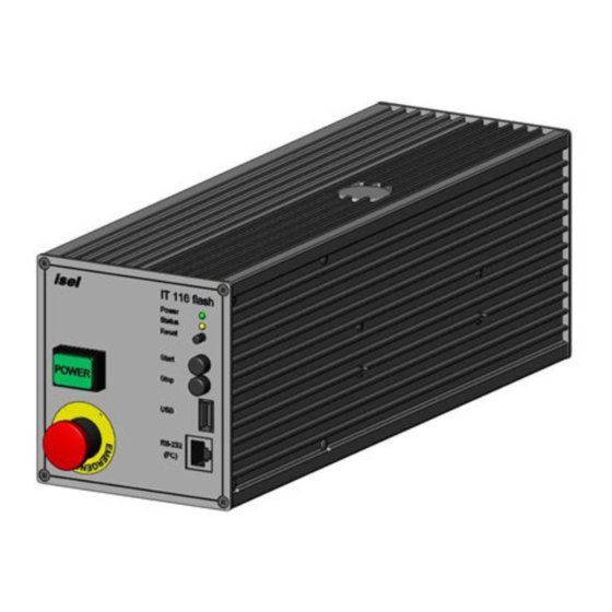
Front Side IT116 Mini / IT116 Flash
Back Side IT116 Mini / IT116 Flash
Figure 1- Motor Module Connector 2- Phase Stepper Motor
Figure 2 - Connection for External Security Circuit
Figure 5 - Impulse Control Connection
Figure 6 - Digital Inputs Wiring
DIP - Switch Settings
Figure 7 - Digital Outputs Wiring
DIP-Switch Settings on IT116 Flash
DIP-Switch Settings on IT116 Mini
5 Electrical Connection and Initial Operation
6 PALPC: User Programming for CNC Mode and Download
Install Programming Software Palpc.exe
User Programming for CNC Mode and Download
7 Declaration of Conformity
8 Bibliography
9 Index
Advertisement
Quick Links
1
Technical Data
2
Front Side It116 Mini / It116 Flash
3
Electrical Connection and Initial Operation
4
Palpc: User Programming for Cnc Mode and Download
Download this manual
isel Germany AG, D-36124 Eichenzell,
IT116 flash
IT116 mini
Operating Instruction
Opera
Eichenzell, Bürgermeister-Ebert-Str. 40
(06659)981-0
(06659)981-776
Table of
Contents
Previous
Page
Next
Page
1
2
3
4
5
Advertisement
Table of Contents
Need help?
Do you have a question about the IT116 flash and is the answer not in the manual?
Ask a question
Questions and answers
Related Manuals for Isel IT116 flash
Controller Isel IT116 mini Operating Instruction
Powerful 1-axis-controllers (25 pages)
Controller Isel iCU-DC Operating Instructions Manual
Cnc servo controller (27 pages)
Controller Isel iMC Series Operating Instructions Manual
Cnc-servo-controller (24 pages)
Controller Isel iMC-S8 Operating Instruction
4-axis-controller (35 pages)
Controller Isel MD24 Instruction Manual
Microstepping driver (19 pages)
Controller Isel CSD 405-IMC Wiring And Operation Manual
4-axes step motor controller (4 pages)
Controller Isel MC1 Series Operating Instructions Manual
1-axis-controller (65 pages)
This manual is also suitable for:
It116 mini
Table of Contents
Print
Rename the bookmark
Delete bookmark?
Delete from my manuals?
Login
Sign In
OR
Sign in with Facebook
Sign in with Google
Upload manual
Upload from disk
Upload from URL


Need help?
Do you have a question about the IT116 flash and is the answer not in the manual?
Questions and answers