
Subscribe to Our Youtube Channel
Related Manuals for Isel MC1 Series


Summary of Contents for Isel MC1 Series
- Page 1 1-axis-controller MC1 series MC1-10 MC1-20 MC1-30 MC1-40 Operating Instruction isel Germany AG, D-36124 Eichenzell, Bürgermeister-Ebert-Str. 40 (06659)981-0 (06659)981-776...
-
Page 2: Table Of Contents
3.2.2 1-axis-controller MC1-20 3.2.3 1-axis-controller MC1-30 3.2.4 1-axis-controller MC1-40 Type independent hardware description of the MC1 series ............12 Description of the base board for all types ................12 4.1.1 Base board pin assignment 4.1.2 Base board jumper settings Control display (MC1-10, MC1-20, MC1-40) ................ 15 Binary user input wiring ...................... - Page 3 1-axis-controller MC1: Operating instruction 9.2.3 Menu SETUP: Initial operation of motor power amplifier IMDxx / control options Software ............................49 10.1 Initial operation and parameterization power amplifiers IMDxx ........... 49 10.1.1 Installing setup programs 10.1.2 Starting setup software and serial connection 10.2 PALPC: User programming for CNC mode and download ..........
-
Page 4: About This Manual
CE norms and marked accordingly. Commissioning of all other parts or components, for which CE safety regulations apply, is prohibited until all respective requests are met. isel Germany AG as the manufacturer cannot take over guarantee if you change the controller in any way. - Page 5 1-axis-controller MC1: Operating instruction Safety symbols Attention This symbol signalizes that there is danger for persons life and health. Danger This symbol signalizes that there is danger for material, machine and environment. Information This symbol signalizes important information. Safety instructions ...
- Page 6 1-axis-controller MC1: Operating instruction Warning! High earth leakage current (ground discharge current, protection conductor current). Before connecting to the AC supply network, it is necessarily required an additional protective grounding. Before connecting the CNC controller to the AC supply network, an additional protective grounding (cross section: 2.5 mm or 4 mm , see...
-
Page 7: Controller Types
- 3-phase-stepper-motors IMD-30 Part-No.: 381518 0030 MC1-40 brushless isel - DC-servo-motors (EC, BL-DC-310V) IMD-40 Part-No.: 381518 0040 All 1-axis-controller have to be used only with the compatible motor type. Please read this operation instruction manual carefully before first use of the controller therewith you can: •... -
Page 8: Technical Data
1-axis-controller MC1: Operating instruction 3 Technical data 3.1 Technical data of series Case dimensions: 204mm (L) x 150mm (W) x 300mm (H) (without the holder for motor cable) Weight: 6550 g Safety class: IP20 Power supply: 230 VAC, 50 Hz, fuse: 4 A 115 VAC, 60 Hz, fuse: 6 A Power consumption: power supply 48VDC: max. - Page 9 Main cable (protection contact plug, IEC-60320 power connector) RS232 communication cable: PC-side: 9 pin Sub-D jack Controller side: RJ45 plug Installation CD PAL-PC 2.1 Installation CD isel-CAN-CNC-control with initial operation program Operation instruction manual in printed form Page - 9...
-
Page 10: Technical Data Of The Controller And Power Amplifier
1-axis-controller MC1: Operating instruction 3.2 Technical data of the controller and power amplifier 3.2.1 1-axis-controller MC1-10 Controller: Controller for linear- or rotational axis with brushed DC servo motor Power supply for intermediate circuit: 48VDC / 500W with PFC Embedded controller MCF52223 with flash memory for firmware update and download of user programs (firmware update ex factory possible) Back side connector (8 pin remote plug) for integration in higher ranked security circuit Protection against short circuit, over- resp. -
Page 11: 1-Axis-Controller Mc1-30
1-axis-controller MC1: Operating instruction 3.2.3 1-axis-controller MC1-30 Controller: Controller for linear- or rotational axis with 3 phase stepper motor Power supply for intermediate circuit: 48VDC / 500W with PFC Motor current up to 10 A (digital current regulation) Embedded controller MCF52223 with flash memory for firmware update and download of user programs (firmware update ex factory possible) Back side connector (8 pin remote plug) for integration in higher ranked security circuit Protection against short circuit, over- resp. -
Page 12: Type Independent Hardware Description Of The Mc1 Series
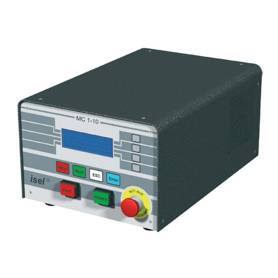
Image 1: front view (for example MC1-10) 4.1 Description of the base board for all types The 1-axis-controller MC1 series base board consists of: user I/Os, embedded controller with LCD and keyboard interface, two serial interfaces (RS232 asynchronous to PC resp. Power amplifier) and security circuit functions (Emergency stop circuit). -
Page 13: Base Board Pin Assignment
1-axis-controller MC1: Operating instruction 4.1.1 Base board pin assignment C1: RS-232-connector to motor amplifier Receive Data Transmit Data C2: Connection of POWER-button, FAULT-signal, Emergency-stop-button in the case front 24VDC operating voltage from 24VDC power supply unit Emergency stop Ch1 (11) Emergency stop switch Emergency stop Ch2 (12) Emergency stop switch... -
Page 14: Base Board Jumper Settings
1-axis-controller MC1: Operating instruction 4.1.2 Base board jumper settings JP2: LC display connection (I2C-Bus) data step JP3: Motor amplifier connection Analog IN+ type dependent used Analog IN- type dependent used Digital GND type dependent used Analog GND type dependent used Enable enable motor amplifier Enable... -
Page 15: Control Display (Mc1-10, Mc1-20, Mc1-40)
1-axis-controller MC1: Operating instruction 4.2 Control display (MC1-10, MC1-20, MC1-40) The controller MC1 has several control displays. These are: Controller-front side: FAULT- lamp (red) -> error in motor power amplifier; no ready signal (READY, 1-aktive = HIGH) will be generated from the motor power amplifier POWER-lamp (green) is on ->... -
Page 16: Binary User Input Wiring
1-axis-controller MC1: Operating instruction 4.3 Binary user input wiring The binary user inputs 1 - 8 of the MC1 are realized using 24V-DC process voltage. The 24VDC reference potential is used from the controller internal 24VDC power supply unit. (no galvanic separation !). -
Page 17: Hardware Description Mc1-10
1-axis-controller MC1: Operating instruction 5 Hardware description MC1-10 5.1 Overview 1-axis-controller MC1-10 contains the following modules: Base board with user I/O, embedded controller with LCD- and keyboard interface, 2 serial interfaces RS232, asynchronous to PC resp. motor power amplifier IMD10, security circuit functions (emergency stop circuit) Motor power amplifier IMD10 Power supply unit 48VDC/500W, power supply unit 24VDC/60W... - Page 18 1-axis-controller MC1: Operating instruction 5-pin motor power plug: Pin (left right) Signal Description Motor line 1 (brown/green) Motor line 2 (white/yellow) Protective ground Brake Output motor brake Brake_GND GND 24V (reference motor brake) 8-pin remote plug: Potential free contact - output Potential free contact - output Emergency stop external Ch2 Emergency stop external Ch2...
-
Page 19: Hardware Description Mc1-20
1-axis-controller MC1: Operating instruction 6 Hardware description MC1-20 6.1 Overview 1-axis-controller MC1-20 contains the following modules: Base board with user I/O, embedded controller with LCD- and keyboard interface, 2 serial interfaces RS232, asynchronous to PC resp. motor power amplifier IMD20, security circuit functions (emergency stop circuit) Motor power amplifier IMD20 Power supply unit 48VDC/500W, power supply unit 24VDC/60W... - Page 20 1-axis-controller MC1: Operating instruction 6-pin motor power plug: Pin (left right) Signal Description Motor line 3 Motor line 2 Motor line 1 Protective ground Brake Output motor brake Brake_GND GND 24V (reference motor brake) 8-pin remote plug: Potential free contact - output Potential free contact - output Emergency stop external Ch2 Emergency stop external Ch2...
-
Page 21: Hardware Description Mc1-30
1-axis-controller MC1: Operating instruction 7 Hardware description MC1-30 7.1 Overview 1-axis-controller MC1-30 contains the following modules: Base board with user I/O, embedded controller with LCD- and keyboard interface, 2 serial interfaces RS232, asynchronous to PC resp. motor power amplifier IMD30, security circuit functions (emergency stop circuit) Motor power amplifier IMD30 Power supply unit 48VDC/500W, power supply unit 24VDC/60W... - Page 22 1-axis-controller MC1: Operating instruction 6-pin motor power plug: Pin (left right) Signal Description Motor line 1 Motor line 2 Motor line 3 Protective ground Brake Output motor brake Brake_GND GND 24V (reference motor brake) 8-pin remote plug: Potential free contact - output Potential free contact - output Emergency stop external Ch2 Emergency stop external Ch2...
-
Page 23: Hardwarebeschreibung Mc1-40
1-axis-controller MC1: Operating instruction 8 Hardwarebeschreibung MC1-40 8.1 Overview 1-axis-controller MC1-40 contains the following modules: Base board with user I/O, embedded controller with LCD- and keyboard interface, 2 serial interfaces RS232, asynchronous to PC resp. motor power amplifier IMD40, security circuit functions (emergency stop circuit) Motor power amplifier IMD40, intermediate circuit: 310VDC Power supply 110V to 230V AC, power supply unit 24VDC/60W... - Page 24 1-axis-controller MC1: Operating instruction M23- motor plug Aderkennzeichnung Beschreibung Motor line U Protective ground Motor line V Motor line W Output motor brake GND 24V (reference motor brake) 8-pin remote plug: Potential free contact - output Potential free contact - output Emergency stop external Ch2 Emergency stop external Ch2 Emergency stop external Ch1...
-
Page 25: Operation Modes And Operation
1-axis-controller MC1: Operating instruction 9 Operation modes and operation 9.1 MC1 operation modes 9.1.1 CNC mode The CNC mode (automatic mode = CNC mode) is the program controlled mode of the 1-axis-controller. That means that a user program which is saved in the controller’s memory (flash) will be executed till the end. - Page 26 1-axis-controller MC1: Operating instruction CNC mode with CONTROL-Option IOonly = On (id est.: active, switched on) No servo axis (linear or rotational axis) with end switches must be connected to the controller A connected axis will not be driven! All motion commands in the user program (e.g.
-
Page 27: Dnc Mode
1-axis-controller MC1: Operating instruction 9.1.2 DNC mode In DNC mode the controller MC1 is connected permanently via RS-232 interface with a control PC (IBM compatible PC or Notebook). A user program stored in flash memory will not be executed. The commands to execute an action/motion (e.g. -
Page 28: Operation (Menu Driven)
1-axis-controller MC1: Operating instruction 9.2 Operation (menu driven) General information for menu driven operation: The symbol in the most right LC display column signalizes that the assigned key (so called soft- key) in case of hitting activates the assigned sub menu ... - Page 29 1-axis-controller MC1: Operating instruction Base menu MC1-xx: CONTROL-Option IOonly = Off m This menu is shown on LC display if serial communication to motor power amplifier IMDxx works after their faultless initialization by power on switch or after software reset. After switching on motor power amplifier operation voltage (POWER button) the controller is ready to operate.
-
Page 30: Menu Program: Program Driven (Automatic Mode)
1-axis-controller MC1: Operating instruction 9.2.1 Menu PROGRAM: program driven (automatic mode) Menu PROGRAM: > Operating actions in menu PROGRAM: Activate soft key Effect activate menu Soft-Key F1 PROGRAM-CNC activate menu Soft-Key F2 PROGRAM-DNC Exit menu PROGRAM; return to base menu MC1-xx Menu PROGRAM-DNC: >... - Page 31 1-axis-controller MC1: Operating instruction Menu PROGRAM-CNC: > > Operating actions in menu PROGRAM-CNC: Activate soft key Effect Start active user program Start = activate CNC mode = start automatic mode Exit menu PROGRAM-CNC; return to menu PROGRAM Active CNC mode (automatic mode) will be shown as following on the LC display: Line 1: number of active command in CNC memory (download section) Line 2:...
-
Page 32: Menu Manual: Manual Operation (Initial Operation Mode)
1-axis-controller MC1: Operating instruction 9.2.2 Menu MANUAL: Manual operation (initial operation mode) This mode allows the use of controller’s basic functions (reference run, absolute and relative positioning, set and reset outputs) by foil keyboard (soft keys F1 – F4). Menu MANUAL: ... - Page 33 1-axis-controller MC1: Operating instruction Menu MOVE Continuous: CONTROL-Option IOonly = Off; LCD line 2 in column 1 marked with M In this menu you can drive the axis continuously with the current displayed velocity (LCD line 3) by pressing soft keys F2 (positive direction) and F3 (negative direction).
- Page 34 1-axis-controller MC1: Operating instruction Menu MOVE Continuous: LCD line 3 in column 1 marked with In this menu you can change the current displayed velocity (line 3) by pressing soft keys F2 (increase velocity) and F3 (reduce velocity). Pressing the ENTER button affects that the standard values 1, 5, 10, 20, 30, 40, 50 or 100 will be set (multiple pressing is possible).
- Page 35 1-axis-controller MC1: Operating instruction Menu MOVE Continuous: LCD line 1 in column 1 marked with M O In this menu you can switch with soft keys F2 (forward) and F3 (backward) between the different motion types.
- Page 36 1-axis-controller MC1: Operating instruction Menu MOVE Pendular: CONTROL-Option IOonly = Off; LCD line 1 marked M O Menu MOVE Pendular: CONTROL-Option IOonly = Off; LCD line 2 marked D Menu MOVE Pendular: CONTROL-Option IOonly = Off; LCD line 3 marked ...
- Page 37 1-axis-controller MC1: Operating instruction Operating actions in menu MOVE Pendular: CONTROL-Option IOonly = Off Activate soft key Effect Change marker position in LCD column 1 in Soft-Key F1 order 1 -> 2 -> 3 -> 1 … Line 1 marked: Switch forward between the different motion types in order: MOVE Continuous ->...
- Page 38 1-axis-controller MC1: Operating instruction Menu MOVE RelPositive: CONTROL-Option IOonly = Off; LCD line 1 marked M O Menu MOVE RelPositive: CONTROL-Option IOonly = Off; LCD line 2 marked D Menu MOVE RelPositive: CONTROL-Option IOonly = Off; LCD line 3 marked ...
- Page 39 1-axis-controller MC1: Operating instruction Operating actions in menu MOVE RelPositive: CONTROL-Option IOonly = Off Activate soft key Effect Change marker position in LCD column 1 in Soft-Key F1 order 1 -> 2 -> 3 -> 1 … Line 1 marked: Switch forward between the different motion types in order: MOVE Continuous ->...
- Page 40 1-axis-controller MC1: Operating instruction Menu MOVE RelNegative: CONTROL-Option IOonly = Off; LCD line 1 marked M O Menu MOVE RelNegative: CONTROL-Option IOonly = Off; LCD line 2 marked D Menu MOVE RelNegative: CONTROL-Option IOonly = Off; LCD line 3 marked ...
- Page 41 1-axis-controller MC1: Operating instruction Operating actions in menu MOVE RelNegative: CONTROL-Option IOonly = Off Activate soft key Effect Change marker position in LCD column 1 in Soft-Key F1 order 1 -> 2 -> 3 -> 1 … Line 1 marked: Switch forward between the different motion types in order: MOVE Continuous ->...
- Page 42 1-axis-controller MC1: Operating instruction Menu MOVE Absolut: CONTROL-Option IOonly = Off; LCD line 1 marked M O Menu MOVE Absolut: CONTROL-Option IOonly = Off; LCD line 2 marked D Menu MOVE Absolut: CONTROL-Option IOonly = Off; LCD line 3 marked ...
- Page 43 1-axis-controller MC1: Operating instruction Operating actions in menu MOVE Absolut: CONTROL-Option IOonly = Off Activate soft key Effect Change marker position in LCD column 1 in Soft-Key F1 order 1 -> 2 -> 3 -> 1 … Line 1 marked: Switch forward between the different motion types in order: MOVE Continuous ->...
- Page 44 1-axis-controller MC1: Operating instruction Menu SET OUTPUT: > In this menu you can manually switch on/off the binary outputs (output 1 – output 8) of the MC1 output port (A1). LCD line 3 shows the current state of the output port A1 binary MSB = Most Significant Bit A1.8 LSB = Least Significant Bit A1.1...
-
Page 45: Menu Setup: Initial Operation Of Motor Power Amplifier Imdxx / Control Options
1-axis-controller MC1: Operating instruction 9.2.3 Menu SETUP: Initial operation of motor power amplifier IMDxx / control options Menu SETUP: > Choose this menu to parameterize motor power amplifier IMDxx via COM interface with the corresponding initial operation software or to activate / deactivate special control options. Operating actions in menu SETUP: Activate soft key Effect... - Page 46 1-axis-controller MC1: Operating instruction Menu SETUP DRIVER: CONTROL-Option IOonly = Off > > In this menu the initial operation / parameterization of motor power amplifier IMDxx can be prepared (refer to section DNC mode). Proceed as follows: 1. Connect the serial interface RS-232 (PC) on the back of the controller with the supplied yellow interface cable to the COM port of the PC / notebook 2.
- Page 47 1-axis-controller MC1: Operating instruction Menu SETUP CONTROL: ▲ ▼ > Choose this menu to activate / deactivate the following control options. To arrive at the upper and lower menu entries use the soft keys F1 and F4 for scrolling up and down. State = On State = Off Control option...
- Page 48 1-axis-controller MC1: Operating instruction EXTstart An active rising edge (Low-High) Program execution will be on input E1.1 = Input 1 started or restarted by pressing starts or restarts a stopped the START-button on the program execution controller front side EXTstop An active rising edge (Low-High) Program execution will be on input E1.2 = Input 2...
-
Page 49: Software
1-axis-controller MC1: Operating instruction 10 Software 10.1 Initial operation and parameterization power amplifiers IMDxx Initial operation / parameterization of motor power amplifiers inside the 1-axis-controller MC1 will be realized with the following initial operation software DCSetup.exe brushed DC-servo-motors ACSetup.exe brushless DC-servo-motors STEPSetup.exe 3-phase stepper motors (future extension with IMD30) in DNC mode of the controller. -
Page 50: Starting Setup Software And Serial Connection
1-axis-controller MC1: Operating instruction 10.1.2 Starting setup software and serial connection DCSetup.exe, ACSetup.exe and STEPSetup.exe are PC based dialog programs (operating system Windows 2000, XP or Vista) for parameterization motor amplifiers IMDxx of 1-axis-controller MC1 via serial interface (RS232). The use of these complex setup programs is described in manuals /1/ and /2/. For initial operation do as follows: 1. - Page 51 1-axis-controller MC1: Operating instruction 5. Start setup program (e.g. DCSetup.exe) from PC / Notebook and set active connection to RS232: 6. In main menu click on Connection RS232-Settings: 7. Set the used PC/Notebook COM interface (COM1…COM4) and baud rate to 57600 baud. Close settings dialog by clicking on button “Open COM Port”: Page - 51...
- Page 52 1-axis-controller MC1: Operating instruction 8. Click on Entry: Connection Online Mode On/Off and start parameter Upload from IMDxx: 9. Do initial operation / parameterization IMDxx (refer to /1/ /2/) e.g. dialog window “Transmission“ for setup encoder resolution, transmission ratio or feed constant: 10.
- Page 53 1-axis-controller MC1: Operating instruction 11. Close setup program on PC/Notebook. 12. Press MC1-xx: STOP-button on the controller front side > Communication between PC/Notebook and IMDxx deactivated, menu SETUP DRIVER is activated > > 13. Press MC1-xx: ESC-button on the controller front side Return to menu SETUP: ...
-
Page 54: Palpc: User Programming For Cnc Mode And Download
1-axis-controller MC1: Operating instruction 10.2 PALPC: User programming for CNC mode and download Creating user programs for 1-axis-controller MC1 is realized with the software PALPC.exe. The implementation method is simple and described in /3/. Analyze technological problem definition: Layout program algorithm (solve problem definition) Implementation of the control algorithm into a PALPC source program *.ppc;... -
Page 55: User Programming For Cnc Mode And Download
10.2.2 User programming for CNC mode and download The use of PALPC and user programming are described in /3/. For 1-axis-controller MC1 series note following specialties: 1. The declaration #control MC1; defines target controller as 1-axis-controller MC1 type, thereby you can use controller specific commands e.g. - Page 56 1-axis-controller MC1: Operating instruction 2. The declaration #steps 1000; defines that the connected axis is a linear axis. All data for positions / move operations (absolute or relative) were specified in mm resp. mm/sec. #steps 3600; defines that the connected axis is a rotation axis. All data for positions / move operations (absolute or relative) were specified in degree resp.
- Page 57 1-Axis-Controller MC1-10 with motor amplifier IMD10 (CNC mode) / Contents: Test program for CNC mode -> request the soft keys F1 to F4 / Created: 27/10/2008, isel Germany AG / ****************************************************************************** #control MC1; / Declare the target controller #axis x;...
- Page 58 Test program in CNC mode -> Send synchronisation character -> Wait for synchronisation character / Created: 27/09/2008, isel Germany AG / ********************************************************************** #control MC1; / Declare MC1 as target controller #axis x; / Declare that only x axis is available #steps 1000;...
- Page 59 Send synchronization characters and wait for synchronization characters /************************************************************************* / File: AbortCondEng.ppc / Created: 27/10/2008, isel Germany AG / Contents: - 1-Axis-Controller MC1-10 with motor amplifier IMD10 (CNC mode) - Test program to demonstrate a motion abort when defining an abort condition...
- Page 60 1-axis-controller MC1: Operating instruction Please proceed as follows: 1. Make serial connection (RS-232) between PC / notebook and MC1 through interface cable. 2. Switch on (POWER button) of the 1-axis-controller MC1 (base menu MC1-xx is shown): m 3.
-
Page 61: Troubleshooting
1-axis-controller MC1: Operating instruction 11 Troubleshooting Fault / Reason Removal Fault: Change COM port in PALPC / setup software. No communication between PC/Notebook and 1-axis- controller MC1. Reason: The used COM port in PALPC / setup software is not set correctly. -
Page 62: Ec Declaration Of Conformity
1-axis-controller MC1: Operating instruction 12 EC Declaration of Conformity EG -Konformitätserklärung Der Hersteller The manufacturer isel Germany AG Bürgermeister-Ebert-Str. 40 D-36124 Eichenzell erklärt hiermit, dass folgendes Produkt hereby declares that the following product Geräteart: 1-Achs-Controller Device: 1-axis controller Typ: für bürstenbehaftete DC-Servomotoren MC1-10 bürstenlose DC-Servomotoren... - Page 63 Definition of minimal operating quality The manufacturer isel Germany AG defines the minimal operating quality for immunity testing for 1-axis- controller MC1-10 / MC1-20 as follows:...
-
Page 64: Bibliography
13 Bibliography DC-Servo positioning module with CANopen-Interface, 11/2007 AC-Servo positioning module with CANopen-Interface, 12/2008 PAL-PC 2.0 programming instruction, 06/2004 14 Index #control ................52 Emergency stop circuit ............. 11 #elev ................. 53 encoder resolution ............49 #steps ................53 external program-start ............7 external program-stop ............ - Page 65 1-axis-controller MC1: Operating instruction Menü MOVE RelPositive ..........35 Menü SET OUTPUT ............41 Menü SETUP ..............42 Scope of delivery ............... 8 MOVE Continuous ............31, 32 serial number ..............52 MOVE RelPositive ............35 soft-key ................25 software reset ..............26 STOP category ..............
Need help?
Do you have a question about the MC1 Series and is the answer not in the manual?
Questions and answers