
Related Manuals for Isel iMC Series


Summary of Contents for Isel iMC Series
- Page 1 CNC-Servo-Controller iMC-B iMC-V Operating Instruction isel Germany AG, D-36124 Eichenzell, Bürgermeister-Ebert-Str. 40 (06659)981-0 (06659)981-776...
- Page 2 CE safety regulations apply, is prohibited until all respective requests are met. isel Germany AG as the manufacturer cannot take over guarantee if you change the controller in any way. The EMC test is valid only for the controllers original configuration ex works, i.e. the delivery state.
-
Page 3: Table Of Contents
iMC-B / iMC-V Operating Instruction Table of contents Introduction ......................4 1.1 Safety symbols ....................4 1.2 Safety instructions.................... 5 Controller types ....................6 Technical data ...................... 7 Hardware description ................... 8 4.1 Controller front side iMC-B / iMC-V ..............8 4.2 Controller back side iMC-B / iMC-V ..............10 4.3 Assembly iMC-B / iMC-V ................16 Initial operation .................... -
Page 4: Introduction
/ iMC-V Operating Instruction 1 Introduction The iMC series CAN-controllers are compact, powerful drive controllers for 2 up to 6 linear or rotational axes. The shapely table housing integrates all control components that are needed for most different automation tasks. They include the control computer, motor power amplifiers, I/O module and security circuit module. -
Page 5: Safety Instructions
iMC-B / iMC-V Operating Instruction 1.2 Safety instructions The CNC-controllers iMC-B and iMC-V are designed in conformability to current technical and recognized rules. The device may only be used if it is in correct condition. Any faults have to be eliminated immediately. Neither children nor non- authorized persons are allowed to put the device into operation. -
Page 6: Controller Types
2 Controller types Controller power Motor type max. axis type amplifier Brushed isel - DC-servo-motors (BDC) iMD10 iMC-B Brushless isel - DC-servo-motors (BLDC) iMD20 iMC-V All controllers have to be used only with the compatible motor type. Please read this operation instruction manual carefully before first use of the controller. -
Page 7: Technical Data
iMC-B / iMC-V Operating Instruction 3 Technical data controller iMC-B iMC-V servo-motor type BDC-servo-motors (brushed DC) BLDC-servo-motors (brushless DC, EC) maximum number of axis 115-230 VAC, 50 … 60 Hz 115-230 VAC, 50 … 60 Hz power supply power supply output 1000 W 1000 W motor power amplifier... -
Page 8: Hardware Description
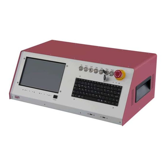
iMC-B / iMC-V Operating Instruction 4 Hardware description 4.1 Controller front side iMC-B / iMC-V 1 - emergency-stop-switch Turns off the power supply for the motor power amplifiers and the working spindle in case of any danger. This means dangers for the users health or machine safety. The integrated security circuit is applicable till safety category 3 (DIN EN945-1). - Page 9 iMC-B / iMC-V Operating Instruction 3 - operation mode switch (key switch) Use this switch to choose between automatic- and setup-mode. In automatic-mode you can only open the cover or safety door of the machine if no axis is in motion and the mounted working spindle is switched off (means that spindle does not turn).
-
Page 10: Controller Back Side Imc-B / Imc-V
iMC-B / iMC-V Operating Instruction 4.2 Controller back side iMC-B / iMC-V ➀ iMC-B connectors for motor-, encoder- and signal lines motor connector (X, Y, Z, A, B, C), 6-pin M23 socket pin signal line color description brown /green motor phase 1 white / yellow motor phase 2 yellow/green... - Page 11 iMC-B / iMC-V Operating Instruction iMC-V connectors for motor-, encoder- and signal lines motor connector (X, Y, Z, A, B, C), 6-pin M23 socket pin signal line color description black 1 motor phase U black 2 motor phase V black 3 motor phase W Brake brown...
- Page 12 This connector is only available on controller without integrated function keys in the case front. It is possible to connect function keys (switches, buttons) from: an external hand control unit an isel CNC control panel with the corresponding connectors on the security circuit module inside the controller case. pin signal...
- Page 13 / iMC-V Operating Instruction ➂ External additional control console connector - 15-pin Sub-D (optional) This connector is used if an additional isel control console is used. pin signal description EM_STOP_1 Emergency stop channel 1, connector 1.1 EM_STOP_1 Emergency stop channel 1, connector 1.2 EM_STOP_2 Emergency stop channel 2, connector 2.1...
- Page 14 iMC-B / iMC-V Operating Instruction ➄ Digital output port - 8-pin, left to right A2.1 – A2.8 The mounted I/O board has two digital output ports each with 8 digital switches. The first output port (A1.1 – A1.8) is internal used for signalization. The second output port can free configured by the user Properties Wiring...
- Page 15 iMC-B / iMC-V Operating Instruction Please note the default connection of the second input –port (E2.1 – E2.8) in the control software Remote / ProNC under the menu entry „Signalization“. These inputs are directly wired with the modules inside the controller.
-
Page 16: Assembly Imc-B / Imc-V
iMC-B / iMC-V Operating Instruction 4.3 Assembly iMC-B / iMC-V CAN I/O 16/16 I/O module Power supply unit 115/230VAC, 48VDC 1000W for motors iMD10/ iMD20 power iSR11 (3) amplifiers control computer with for brushed DC integrated CAN-PCI-card servo-motors / and CAN-I/O-module brushless DC-servo-motors iSM 5 security... -
Page 17: Initial Operation
iMC-B / iMC-V Operating Instruction 5 Initial operation Preparation Before power up of the controller please check the scope of delivery. Following parts should be included: net cable operating instruction Make all necessary connections: connect net cable connect motor- and encoder-lines (motors) with the connectors on the back side of the controller Check all other connected cables Initial operation... -
Page 18: Software
iMC-B / iMC-V Operating Instruction 6 Software 6.1 Installing setup software Setup / initial operation of the integrated power amplifiers inside the controller’s iMC- B, iMC-V and iMC-VP takes place by the following setup software DCSetup.exe (1) for: BDC-servo-motors (brushed-DC-servos) with motor power amplifiers iMD10 ACSetup.exe (2) for:... - Page 19 iMC-B / iMC-V Operating Instruction 3. Click on the entry “Installation of control software“. The following window will be shown: Choose now the setup software depending on your motor type and click on the “Installation of entry to start the installation. (in this example ACSetup“) Follow the instructions of the setup assistant.
-
Page 20: Pronc / Remote Installation And First Steps
iMC-B / iMC-V Operating Instruction ProNC / Remote installation and first steps Operation of the controller iMC-B / iMC-V takes place either with the control software Remote or with the control / programming software ProNC. If there is no operation software installed ex factory do the following steps to install the software later: 1. - Page 21 After finishing the installation click on button “Exit“ to close the Auto-Start-menu. 4. Open the configuration program CANSet.exe (shortcut on windows-desktop or start-menu-entry: Start Programs isel CAN-CNC-Control CANSet) to setup machine specific parameters (CAN-interface, used axes, axis type).
- Page 22 iMC-B / iMC-V Operating Instruction 5. Open the control software ProNC / Remote via shortcut on the windows desktop or the start menu entry: Start Programs CNCworkbench ProNC/Remote Click on entry “control“ in menu “settings“. Mark the entry Motion control modules ...
-
Page 23: Ec - Declaration Of Conformity
/ iMC-V Operating Instruction 7 EC - Declaration of Conformity Der Hersteller The manufacturer isel Germany AG Bürgermeister-Ebert-Str. 40 D-36124 Eichenzell erklärt hiermit, dass folgendes Produkt hereby declares that the following product Geräteart: CAN-Servo-Controller Device: CAN- servo controller Typ:... -
Page 24: Bibliography
/ iMC-V Operating Instruction 8 Bibliography 1. isel Germany AG. Positioniermodul mit CanOpen Interface UVE8112 / iMD10. 03/2008. 2. isel Germany AG. positioning module with CanOpen interface iMD20 / iMD40. 03/2009. 3. isel Germany AG. ProNC User Manual. 2003.
Need help?
Do you have a question about the iMC Series and is the answer not in the manual?
Questions and answers