Table of Contents

Related Manuals for Isel MD24


Summary of Contents for Isel MD24
- Page 1 MD24 / MD28 Microstepping Driver odul Instruction Manual Hardware Description Item-no. 970317 BE001 Last update: 01/2010 ® Germany AG D-36124 Eichenzell Bürgermeister-Ebert-Str. 40 +49/(0)6659/981-700 isel +49/(0)6659/981-776...
- Page 2 All rights reserved. No part of our prints may either be reproduced in any form (print, photography or another procedure) or processed, copied or published by ® using electronic systems without written permission of isel ® Manufacturer: isel Germany AG Buergermeister-Ebert-Straße 40...
-
Page 3: Table Of Contents
9 Power Supply Selection ..................9 Regulated or Unregulated Power Supply ............. 9 Multiple Drivers ................... 10 10 Selecting Microstep Resolution and Driver Output Current ......10 10.1 Microstep Resolution Selection ..............10 10.1.1 MD24 10.1.2 MD28 10.2 Current Settings ..................11 10.2.1 MD24 10.2.2... - Page 4 13 Sequence Chart of Control Signals ..............13 14 Protection Functions ..................14 15 Problem Symptoms and Possible Causes ............15...
-
Page 5: Introduction
MD24 / MD28 – Hardware Description 1 Introduction The MD24 / MD28 are economical microstepping driver based on patented technology. It is suitable for driving 2-phase and 4-phase hybrid stepping motors. By using the advanced bipolar-current chopping technique, it can output more speed and torque from the same motor, compared with traditional drivers, such as L/R drivers. -
Page 6: Safety Instructions
MD24 / MD28 – Hardware Description 2 Safety Instructions The MD24 / MD28 modules are designed according to the current state of the art and the accepted safety-relevant rules. The devices may only be actuated in perfect technical condition. Failures are to be eliminated immediately. -
Page 7: Technische Daten
MD24 / MD28 – Hardware Description 3 Technische Daten MD 24 MD 28 Min. Typ. Max. Min. Typ. Max. Output current [A] Supply voltage [V] Logic signal current [mA] Pulse input frequency [KHz] Isolation resistance [MΩ] Cooling Natural Cooling or Forced cooling... -
Page 8: Pin Assignment
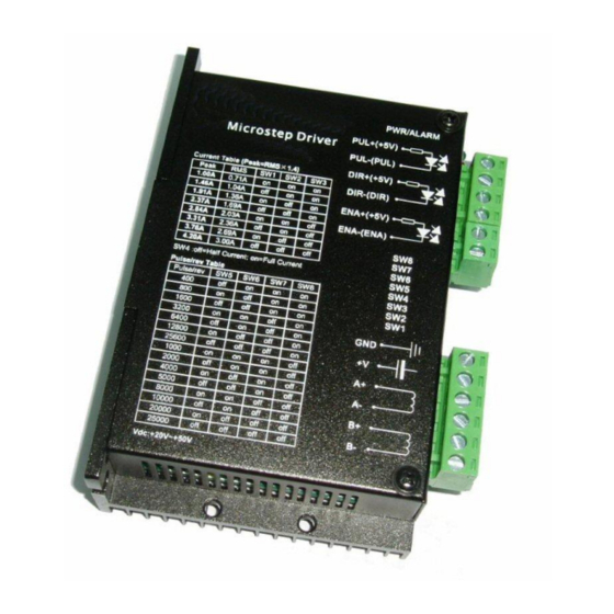
MD24 / MD28 – Hardware Description 5 Pin Assignment 5.1 P1 - Control-Signals Phoenix 6-pin. Signal Description PUL+(+5V) Pulse signal: In single pulse (pulse/direction) mode, this input represents pulse signal, effective for each rising or falling edge (set by inside jumper J1);... -
Page 9: Jumpers
MD24 / MD28 – Hardware Description 6 Jumpers There are two jumpers J1 and J2 inside the MD24 / MD28 specifically for the purpose of selecting effective pulse edge or effective level and control signal mode, as shown in figure 2. Default setting is PUL/DIR mode and upward-rising edge effective. -
Page 10: Control Signal Connector (P1) Interface
The MD24 / MD28 can accept differential and single-ended inputs (including open-collector and PNP output). The MD24 / MD28 has 3 optically isolated logic inputs which are located on connector P1 to accept line driver control signals. These inputs are isolated to minimize or eliminate electrical noises coupled onto the drive control signals. -
Page 11: Connecting The Motor (P2)
MD24 / MD28 – Hardware Description 8 Connecting the Motor (P2) The ME542 driver can drive any 2-pahse and 4-pahse hybrid stepping motors. 8.1 Connections to 4-lead Motors 4 lead motors are the least flexible but easiest to wire. Speed and torque will depend on winding inductance. -
Page 12: Full Coil Configurations
MD24 / MD28 – Hardware Description 8.2.2 Full Coil Configurations The full coil configuration on a six lead motor should be used in applications where higher torque at lower speeds is desired. This configuration is also referred to as full copper. In full coil mode, the motors should be run at only 70% of their rated current to prevent overheating. -
Page 13: Parallel Connections
8-lead motor parallel connections 9 Power Supply Selection The MD24 / MD28 can match medium and small size stepping motors (from Nema size 17 to 34) made by any motor manufactures around the world. To achieve good driving performances, it is important to select supply voltage and output current properly. -
Page 14: Multiple Drivers
MD24 / MD28 – Hardware Description 9.2 Multiple Drivers It is recommended to have multiple drivers to share one power supply to reduce cost, if the supply has enough capacity. To avoid cross interference, DO NOT daisy-chain the power supply input pins of the drivers. (Instead, please connect them to power supply separately.) -
Page 15: Md28
MD24 / MD28 – Hardware Description 10.1.2 MD28 Mikrostep Schritte/Umdr. SW5 SW6 SW7 SW8 1600 3200 6400 12800 25600 51200 1000 2000 4000 5000 8000 10000 20000 40000 10.2 Current Settings For a given motor, higher driver current will make the motor to output more torque, but at the same time causes more heating in the motor and driver. -
Page 16: Md28
MD24 / MD28 – Hardware Description 10.2.2 MD28 Peak current [A] Nennstrom [A] SW2 SW3 2,80 2,00 3,50 2,50 4,20 3,00 4,90 3,50 5,70 4,10 6,40 4,53 7,00 5,00 7,80 5,57 Achtung: Durch die Induktivität des Motors, kann der aktuelle Motorstrom kleiner sein, als der eingestellte Ausgangsstrom, insbesondere bei hohen Drehzahlen! 10.3 Standstill Current Setting... -
Page 17: Typical Connection
MD24 / MD28 – Hardware Description 12 Typical Connection A complete stepping system should include stepping motor, stepping driver, power supply and controller (pulse generator). A typical connection is shown as figure 10. 13 Sequence Chart of Control Signals In order to avoid some fault operations and deviations, PUL, DIR and ENA signals must... - Page 18 To improve reliability, the driver incorporates some built-in protections features. Over-voltage protection When power supply voltage of the MD24 exceeds +52VDC or of the MD28 exceeds +96VDC, protection will be activated and power indicator LED will turn red. When power supply voltage is lower than +22VDC, the driver will not works properly.
- Page 19 MD24 / MD28 – Hardware Description 15 Problem Symptoms and Possible Causes Symptoms Possible problem Motor is not rotating No power Microstep resolution setting is wrong DIP switch current setting is wrong Fault condition exists The driver is disabled Motor rotates in the wrong...
Need help?
Do you have a question about the MD24 and is the answer not in the manual?
Questions and answers