
Related Manuals for Crestron MPC-M50


Summary of Contents for Crestron MPC-M50
- Page 1 Crestron MPC-M50 MPC Media Presentation Controller™ Operations & Installation Guide...
-
Page 2: Regulatory Compliance
This product is Listed to applicable UL Standards and requirements by Underwriters Laboratories Inc. As of the date of manufacture, the MPC-M50 has been tested and found to comply with specifications for CE marking and standards per EMC and Radiocommunications Compliance Labelling. -
Page 3: Table Of Contents
Crestron MPC-M50 Media Presentation Controller Contents ™ MPC Media Presentation Controller : MPC-M50 Introduction ..........................1 Features and Functions ....................1 Applications......................... 4 Specifications ......................5 Physical Description....................7 Setup ............................12 Network Wiring......................12 Identity Code ......................12 Supplied Hardware ....................13 Installation ......................... -
Page 5: Mpc Media Presentation Controller
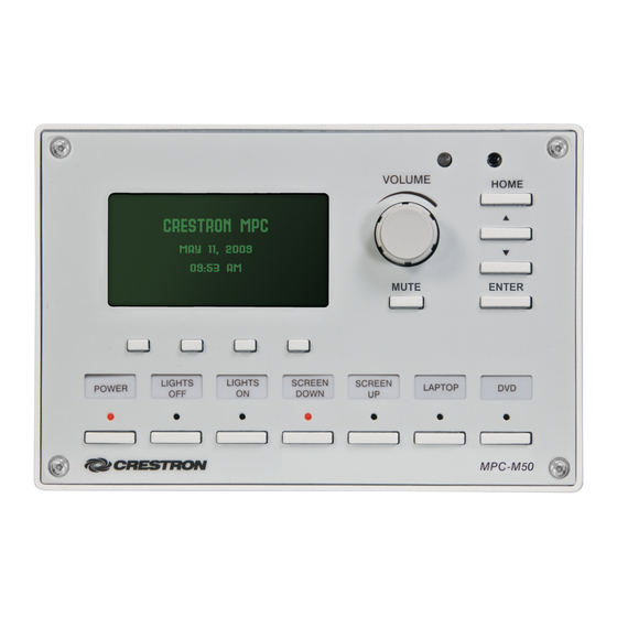
Available in black or white, the MPC-M50 is constructed to handle the rigors of everyday use in a corporate or educational environment. Numerous programmable control ports afford plentiful connectivity for a roomful of audio, video and lighting ®... - Page 6 Crestron MPC-M50 Control…Simplified The MPC-M50 is engineered to be easy to integrate and use, yet versatile enough to suit each application perfectly. Its front panel features a large LCD display with four “soft keys” plus seven “hard keys” buttons with LED feedback and a volume control knob, all which can be freely programmed for controlling system functions like power, source selection, transport control, audio settings, lighting and much more.
- Page 7 Ambient Light Sensor The MPC-M50’s built-in light sensor has a range of uses, from controlling its own backlight intensity to providing ambient lighting level data to a central building management system.
-
Page 8: Applications
Media Presentation Controller Crestron MPC-M50 Applications The following diagrams show an MPC-M50 in a residential application. MPC-M50 in a Residential Application 4 • Media Presentation Controller: MPC-M50 Operations & Installation Guide – DOC. 6814B... -
Page 9: Specifications
Crestron MPC-M50 Media Presentation Controller Specifications Specifications for the MPC-M50 are listed in the following table. MPC-M50 Specifications SPECIFICATION DETAILS Processor ® 32-bit Freescale ColdFire Microprocessor Memory SDRAM 32 MB NVRAM 256 KB Flash 8 MB Time Clock Accuracy ± 1 minute per year... - Page 10 Crestron Authorized Independent Programmers (CAIP) only. New users may be required to register to obtain access to certain areas of the site (including the FTP site). 6 • Media Presentation Controller: MPC-M50 Operations & Installation Guide – DOC. 6814B...
-
Page 11: Physical Description
Media Presentation Controller Physical Description This section provides information on the connections, controls and indicators available on your MPC-M50. MPC-M50 Physical View (Front) MPC-M50 Physical View (Rear) Media Presentation Controller: MPC-M50 • 7 Operations & Installation Guide – DOC. 6814B... - Page 12 Media Presentation Controller Crestron MPC-M50 MPC-M50 Overall Dimensions (Front View) 4.50 in (114 mm) 6.70 in (170 mm) MPC-M50 Overall Dimensions (Rear and Side Views) 0.95 in (24 mm) 2.60 in (66 mm) 1.90 in (48 mm) 17 18 2.23 in (57 mm) 8 •...
- Page 13 (2) Sets of (4) captive screw terminals Cresnet port and 24 VDC power input with parallel pass-through Master/Slave selectable 24: Power (24 VDC) Data Data G: Ground (Continued on following page) Media Presentation Controller: MPC-M50 • 9 Operations & Installation Guide – DOC. 6814B...
- Page 14 Rated 1 A, 30 VAC/DC (One group of three shown) MOV arc suppression across contacts DESCRIPTION Common Each pair of inputs shares a common. Common Common (Continued on following page) 10 • Media Presentation Controller: MPC-M50 Operations & Installation Guide – DOC. 6814B...
- Page 15 To determine which is pin 1 on the cable, hold the cable so the end of the eight pin modular jack is facing away from you, with the clip down and copper side up. Pin 1 is on the far left. Media Presentation Controller: MPC-M50 • 11 Operations & Installation Guide – DOC. 6814B...
-
Page 16: Setup
Identity Code Net ID The Net ID of the MPC-M50 has been factory set to 02. This Net ID is defined as the “Master” control system. The Net IDs of multiple MPC-M50 devices in the same system must be unique; this means there will be a master/slave relationship between units (only the Net ID of the master will be left at 02). -
Page 17: Supplied Hardware
Crestron MPC-M50 Media Presentation Controller Supplied Hardware The hardware supplied with the MPC-M50 is listed in the following table. Supplied Hardware for the MPC-M50 DESCRIPTION PART NUMBER QUANTITY Mounting Plate with Ground Wire 4506280 Button Identification Labels, Sources, 100 4509400... - Page 18 4. Attach cables to the rear of the MPC-M50. Refer to “Hardware Hookup” which starts on page 16. 5. Use the two included 04-40 x 1/4” screws to attach the MPC-M50 to the mounting plate. CAUTION: Excess wire that is pinched between the MPC-M50 and the electrical box could short out.
- Page 19 7. Attach the included labels in the appropriate positions on the MPC-M50. 8. Perform any necessary programming using the COMPUTER (USB) connection prior to attaching the front panel of the MPC-M50. (Programming can also be performed via the LAN port.) 9. Remove the protective coating that covers the LCD display.
-
Page 20: Hardware Hookup
Refer to “Network Wiring” on page 12 before attaching the 4-position terminal block connector. Apply power after all connections have been made. When making connections to the MPC-M50, use Creston power supplies for Crestron equipment. NOTE: When connecting the included power supply to the NET connector on the unit, make sure the lead with the white stripes goes to the terminal marked 24. - Page 21 From Digital or Devices Analog Devices INPUT Connections Depending on the application, the MPC-M50 INPUTS can be wired multiple ways. Refer to the following diagrams when wiring INPUTS. CAUTION: Incorrect wiring may damage the MPC-M50. Media Presentation Controller: MPC-M50 • 17...
- Page 22 Pull-up Resistor: Disabled Enabled Label the Buttons Optional custom engraved labels for the MPC-M50 can be ordered separately by using Crestron Engraver software, available from the Crestron Web site (www.crestron.com). 18 • Media Presentation Controller: MPC-M50 Operations & Installation Guide – DOC. 6814B...
-
Page 23: Programming Software
Web site and examine the extensive help file. Programming with SIMPL Windows NOTE: While SIMPL Windows can be used to program the MPC-M50, it is recommended to use SystemBuilder for configuring a system. SIMPL Windows is Crestron’s premier software for programming Crestron control systems. -
Page 24: Push Button Programming
Media Presentation Controller Crestron MPC-M50 Locating the MPC-M50 in the Device Library Program Manager Program Manager is the view where programmers “program” a Crestron control system by assigning signals to symbols. The symbol can be viewed by double clicking on the icon or dragging it into Detail View. -
Page 25: Uploading And Upgrading
MPC-M50 Crestron Toolbox The COMPUTER port on the MPC-M50 connects to the USB port on the PC via a Type A to Type B USB cable (not included): 1. Use the Address Book in Crestron Toolbox to create an entry using the expected communication protocol (USB). -
Page 26: Programs And Firmware
Ethernet Communication The MPC-M50 connects to PC via Ethernet: 1. Establish USB communication between MPC-M50 and PC. 2. Enter the IP address, IP mask and default router of the MPC-M50 via the Crestron Toolbox (Functions | Ethernet Addressing); otherwise enable DHCP. -
Page 27: Problem Solving
Verify power supply lead with function. connected properly. white stripes is connected to NET connector terminal marked 24 . The other lead should be connected to the terminal marked G . Media Presentation Controller: MPC-M50 • 23 Operations & Installation Guide – DOC. 6814B... -
Page 28: System Monitor
NOTE: If your PC does not have the USB driver installed, after connecting the MPC-M50 to the PC using the USB cable, you will see a dialog box on your PC screen asking you to install the USB driver. For instructions on how to install the USB driver, refer to the Crestron Toolbox help file. -
Page 29: Check Network Wiring
NOTE: All Crestron certified Cresnet wiring must consist of two twisted pairs. One twisted pair is the +24V conductor and the GND conductor and the other twisted pair is the Y conductor and the Z conductor. Media Presentation Controller: MPC-M50 • 25 Operations & Installation Guide – DOC. 6814B... -
Page 30: Reference Documents
Future Updates As Crestron improves functions, adds new features and extends the capabilities of the MPC-M50, additional information may be made available as manual updates. These updates are solely electronic and serve as intermediary supplements prior to the release of a complete technical documentation revision. -
Page 31: Software License Agreement
Software. The failure of either party to enforce any right or take any action in the event of a breach hereunder shall constitute a waiver unless expressly acknowledged and set forth in writing by the party alleged to have provided such waiver. Media Presentation Controller: MPC-M50 • 27 Operations & Installation Guide – DOC. 6814B... - Page 32 MERCHANTABILITY OR FITNESS FOR ANY PARTICULAR PURPOSE, OR ANY OTHER WARRANTIES, NOR AUTHORIZES OTHER PARTY OFFER WARRANTIES, INCLUDING WARRANTIES MERCHANTABILITY FOR THIS PRODUCT. THIS WARRANTY STATEMENT SUPERSEDES ALL PREVIOUS WARRANTIES. 28 • Media Presentation Controller: MPC-M50 Operations & Installation Guide – DOC. 6814B...
-
Page 33: Return And Warranty Policies
Any implied warranties that may be imposed by law are limited to the terms of this limited warranty. This warranty statement supersedes all previous warranties. Media Presentation Controller: MPC-M50 • 29 Operations & Installation Guide – DOC. 6814B... - Page 34 Media Presentation Controller Crestron MPC-M50 This page is intentionally left blank. 30 • Media Presentation Controller: MPC-M50 Operations & Installation Guide – DOC. 6814B...
- Page 35 Crestron MPC-M50 Media Presentation Controller This page is intentionally left blank. Media Presentation Controller: MPC-M50 • 31 Operations & Installation Guide – DOC. 6814B...
- Page 36 Crestron Electronics, Inc. Operations & Installation Guide – DOC. 6814B 15 Volvo Drive Rockleigh, NJ 07647 (2024142) Tel: 888.CRESTRON 04.11 Fax: 201.767.7576 Specifications subject to www.crestron.com change without notice.
Need help?
Do you have a question about the MPC-M50 and is the answer not in the manual?
Questions and answers