Lochinvar RESIDENTIAL GAS WATER HEATERS Instruction Manual
Hide thumbs
Also See for RESIDENTIAL GAS WATER HEATERS:
- Use and care manual with installation instructions (40 pages) ,
- Instruction manual (32 pages)
Table of Contents
Advertisement
Instruction Manual
RESIDENTIAL GAS WATER HEATERS
NOT FOR USE IN MANUFACTURED (MOBILE) HOMES
•
•
For Your Safety
AN ODORANT IS ADDED TO THE GAS USED
BY THIS WATER HEATER.
ALL TECHNICAL AND WARRANTY QUESTIONS: SHOULD BE DIRECTED TO THE LOCAL DEALER FROM WHOM THE WATER HEATER WAS
PURCHASED. IF YOU ARE UNSUCCESSFUL, PLEASE WRITE TO THE COMPANY LISTED ON THE RATING PLATE ON THE WATER HEATER.
KEEP THIS MANUAL IN THE POCKET ON HEATER FOR FUTURE REFERENCE
WHENEVER MAINTENANCE ADJUSTMENT OR SERVICE IS REQUIRED.
PRINTED 0409
315628-000
1
Advertisement
Table of Contents

Related Manuals for Lochinvar RESIDENTIAL GAS WATER HEATERS


Summary of Contents for Lochinvar RESIDENTIAL GAS WATER HEATERS
-
Page 1: Instruction Manual
Instruction Manual RESIDENTIAL GAS WATER HEATERS NOT FOR USE IN MANUFACTURED (MOBILE) HOMES • • For Your Safety AN ODORANT IS ADDED TO THE GAS USED BY THIS WATER HEATER. ALL TECHNICAL AND WARRANTY QUESTIONS: SHOULD BE DIRECTED TO THE LOCAL DEALER FROM WHOM THE WATER HEATER WAS PURCHASED. -
Page 2: Safe Installation, Use And Service
SAFE INSTALLATION, USE AND SERVICE Your safety and the safety of others is extremely important in the installation, use and servicing of this water heater. Many safety-related messages and instructions have been provided in this manual and on your own water heater to warn you and others of a potential injury hazard. -
Page 3: General Safety
GENERAL SAFETY... -
Page 4: Table Of Contents
TABLE OF CONTENTS SAFE INSTALLATION, USE AND SERVICE ........2 Draft Hood Operation ............ 17 GENERAL SAFETY ..............3 Condensation ............17,18 TABLE OF CONTENTS ............... 4 Smoke/Odor ..............18 INTRODUCTION ................. 4 Thermal Expansion ............18 Preparing for the New Installation ........4 Strange Sounds ............ -
Page 5: Typical Installation
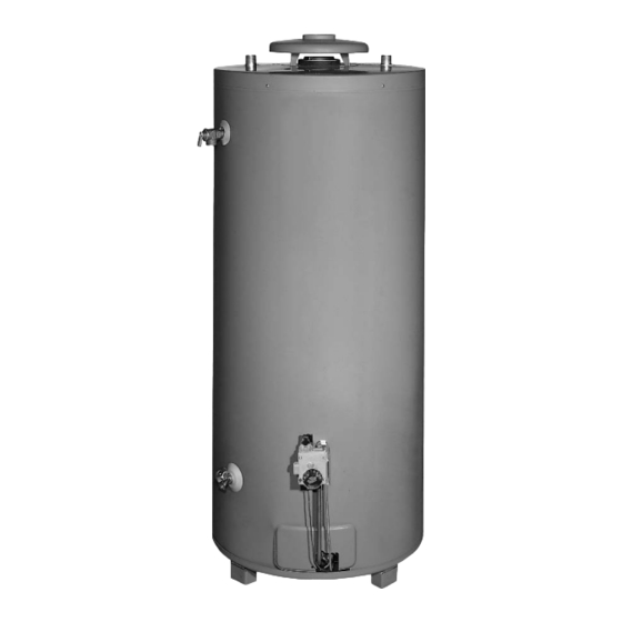
TYPICAL INSTALLATION GET TO KNOW YOUR WATER HEATER - GAS MODELS A Vent Pipe I Ground Joint Union Temperature-Pressure Relief Valve B Drafthood J Drip Leg (Sediment Trap) Rating Plate C Anode K Inner Door Flue Baffle(s) D Hot Water Outlet L Outer door Gas Control Valve/Thermostat Outlet... -
Page 6: Mixing Valve Usage
TYPICAL INSTALLATION MIXING VALVE USAGE FIGURE 2. This appliance has been design certified as complying with ANSI Z21.10.3 HOTTER WATER CAN SCALD: current edition for water heaters and is considered suitable for: Water heaters are intended to produce hot water. Water heated to Water (Potable) Heating and Space Heating: All models are a temperature which will satisfy space heating, clothes washing, considered suitable for water (potable) heating and space heating. -
Page 7: Locating The New Water Heater
LOCATING THE NEW WATER HEATER FACTS TO CONSIDER ABOUT THE LOCATION Carefully choose an indoor location for the new water heater, because the placement is a very important consideration for the safety of the occupants in the building and for the most economical use of the appliance. -
Page 8: Insulation Blankets
Minimum clearances between the water heater and combustible materials INSULATION BLANKETS are 0 inch at the sides and rear, 4” (102 mm) at the front, and 6” (153 mm) from the vent pipe. Clearance from the top of the jacket is 12” (305 mm) on most models. - Page 9 A. ALL AIR FROM INSIDE BUILDINGS: (See Figures 4 and 5) The confined space shall be provided with two permanent openings communicating directly with an additional room(s) of sufficient volume so that the combined volume of all spaces meets the criteria for an unconfined space.
-
Page 10: Installing The New Water Heater
INSTALLING THE NEW WATER HEATER WATER PIPING As water is heated, it expands (thermal expansion) and closed systems do not allow for the expansion of heated water. The water within the water heater tank expands as it is heated and increases the pressure of the water system. -
Page 11: Temperature-Pressure Relief Valve
Figure 9 shows the typical attachment of the water piping to the water heater. The water heater is equipped with 1” NPT threaded nipple (75 gallon models) or 1.25” NPT threaded nipple (100 gallon models) water connections. NOTE: If using copper tubing, solder tubing to an adapter before attaching the adapter to the cold water inlet connection. -
Page 12: Filling The Water Heater
Vent dampers must bear evidence of certification as complying with FILLING THE WATER HEATER the current edition of the American National Standard ANSI Z21.66 CGA 6.14 (covering electrically and mechanically actuated vent dampers). Before installation of any vent damper, consult the local gas utility for further information. -
Page 13: Gas Piping
Make sure the gas supplied is the same type listed on the model rating plate. The inlet gas pressure must not exceed 14 inch water column (2.6 kPa) for natural and propane (L.P.) gas. The minimum inlet gas pressure shown on the rating plate is that which will permit firing at rated input. -
Page 14: Sediment Traps
FIGURE 14. GAS PIPING WITH ALL BLACK IRON PIPE TO GAS CONTROL. SEDIMENT TRAPS Use pipe joint compound or teflon tape marked as being resistant to the action of petroleum [Propane (L.P.)] gases. A sediment trap shall be installed as close to the inlet of the water The appliance and its gas connection must be leak tested before heater as practical at the time of water heater installation. -
Page 16: Lighting & Operating Instructions
FOR YOUR SAFETY READ BEFORE LIGHTING WARNING: If you do not follow these instructions exactly, a fire or explosion may result causing property damage, personal injury or loss of life. BEFORE LIGHTING: ENTIRE SYSTEM MUST BE FILLED WITH WATER AND AIR PURGED AT FAUCETS This appliance has a pilot which must be lighted by hand. -
Page 17: Temperature Regulation
TEMPERATURE REGULATION Never allow small children to use a hot water tap, or to draw their Short repeated heating cycles caused by small hot water uses can own bath water. Never leave a child or handicapped person cause temperatures at the point of use to exceed the thermostat setting unattended in a bathtub or shower. -
Page 18: Smoke/Odor
OPERATIONAL CONDITIONS Because of the suddenness and amount of water, condensation water may be diagnosed as a “tank leak”. After the water in the tank warms up (about 1-2 hours), the condition should disappear. SMELLY WATER In each water heater there is installed at least one anode rod (see Do not assume the water heater is leaking until there has been enough parts section) for corrosion protection of the tank. -
Page 19: Periodic Maintenance
PERIODIC MAINTENANCE You should check for sooting. Soot is not normal and will impair proper VENTING SYSTEM INSPECTION combustion. Soot build-up indicates a problem that requires correction before further use. Turn “OFF” gas to water heater and leave off until repairs are made, because failure to correct the cause of the sooting can result in a fire causing death, serious injury, or property damage. -
Page 20: Anode Rod Inspection
INSTALLED IN SUITABLE AREA: To insure sufficient ventilation and In replacing the anode: combustion air supply, proper clearances from the water heater must be maintained. See “Locating the New Water Heater” section. 1. Turn off gas supply to the water heater. Combustible materials such as clothing, cleaning materials, or flammable liquids, etc. -
Page 21: Service
DRAINING AND FLUSHING 3. Turning counterclockwise ( ), remove the hex cap below the screw handle. 4. Remove the was her and put the new one in place. 5. Screw the handle and cap assembly back into the drain valve and retighten using a wrench. -
Page 22: Leakage Checkpoints
LEAKAGE CHECKPOINTS Read this manual first. Then before checking the water heater make sure the gas supply has been turned “OFF”, and never turn the gas “ON” before the tank is completely full of water. Never use this water heater unless it is completely filled with water. To prevent damage to the tank, the tank must be filled with water. -
Page 23: Repair Parts
REPAIR PARTS Key No. Part Description Pipe Nipple Burner Tube Burner Head Thermocouple Pilot Draft Hood Draft Hood Brace Inlet Tube Flue Baffle Assembly Anode Rod Cleanout Cover (Optional) Cleanout Gasket (Optional) Cleanout Screw (Optional) Inner Door Outer Door Gas Control Valve/Thermostat T &... -
Page 24: Troubleshooting Guidelines
TROUBLESHOOTING GUIDELINES These guidelines should be utilized by a qualified service agent. Problem Cause Solution Improperly sealed, hot or cold supply connection, Tighten threaded connections. relief valve, drain valve, or thermostat threads. WATER LEAKS Leakage from other appliances or water lines. Inspect other appliances near water heater. - Page 25 NOTES...
- Page 26 NOTES...
- Page 27 NOTES...
Need help?
Do you have a question about the RESIDENTIAL GAS WATER HEATERS and is the answer not in the manual?
Questions and answers