Table of Contents
Advertisement
100332297_2000589045_Rev A
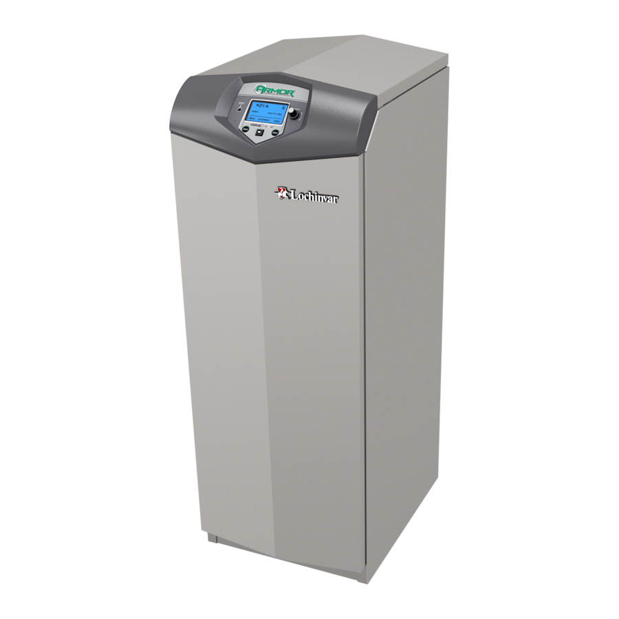
Service Manual
Models: 400 - 1000
Series 100 & 101
WARNING
This manual must only be used by
a qualified heating installer / service
technician. Read all instructions,
including this manual and the Armor
Installation and Operation Manual,
before installing. Perform steps in the
order given. Failure to comply could
LOW LEAD CONTENT
result in severe personal injury, death,
or substantial property damage.
Save this manual for future reference.
Advertisement
Table of Contents


Need help?
Do you have a question about the Armor 100 Series and is the answer not in the manual?
Questions and answers