Lochinvar 000 - 500 Installation & Service Manual
90,000 - 500,000 btu/hr
Hide thumbs
Also See for 000 - 500:
- Installation and service manual (52 pages) ,
- Installation and service manual (48 pages)
Table of Contents
Advertisement
Quick Links
CFA-I-S Rev A
Installation & Service Manual
Models: 90,000 - 500,000 Btu/hr
WARNING:
This manual supplies information for the
installation, operation, and servicing of the
appliance. It is strongly recommended that this
manual be reviewed completely before proceeding
with an installation. Perform steps in the order
given. Failure to comply could result in severe
personal injury, death, or substantial property
damage.
Save this manual for future reference.
Advertisement
Table of Contents

Related Manuals for Lochinvar 000 - 500


Summary of Contents for Lochinvar 000 - 500
- Page 1 CFA-I-S Rev A Installation & Service Manual Models: 90,000 - 500,000 Btu/hr WARNING: This manual supplies information for the installation, operation, and servicing of the appliance. It is strongly recommended that this manual be reviewed completely before proceeding with an installation. Perform steps in the order given.
-
Page 2: Table Of Contents
Pump Operation ....... 47 Figure 7-1_Single Water Heater Piping w/Single Tank . . 48 Figure 7-2_Single Water Heater Piping w/Multiple Tanks 49 Figure 7-3_Multiple Water Heater Piping w/Single Tank . -
Page 3: Please Read Before Proceeding
Please read before proceeding This is a gas appliance and should be NOTICE installed by a licensed electrician and/or certified gas supplier. performed by a qualified service installer, service agency or the gas supplier. WARNING If the information in these instructions is not followed exactly, a fire or explosion may result causing property damage, personal injury, or death. - Page 4 Please read before proceeding To minimize the possibility of serious WARNING personal injury, fire, or damage to your appliance, never violate the following safety rules: 1. Boilers and water heaters are heat producing appliances. To avoid damage or injury, do not store materials against the appliance or the vent-air intake system.
-
Page 5: Ratings
Ratings I=B=R Rating Input Model Number Note: Change “N” to (Note 4) “L” for L.P. gas models. CBN315 CBN360 CBN399 CBN500 Maximum allowed working pressure is located on the rating plate. NOTICE Notes: 1. The ratings are based on standard test procedures prescribed by the United States Department of Energy. - Page 6 Ratings Model Number Input Note: Change “N” to “L” for L.P. gas models CWN090 CWN135 CWN180 CWN199 CWN225 CWN270 CWN315 CWN360 CWN399 CWN500 Maximum allowed working pressure is located on the rating plate. NOTICE Notes: 1. Copper-fins require special gas venting. Use only the vent materials and methods specified in the Installation and Service Manual.
-
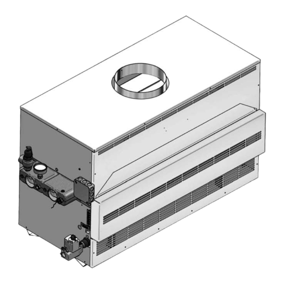
Page 7: The Copper-Fin --How It Works
13. Temperature gauge (CW models only) The temperature gauge monitors the inlet temperature of the water heater as well as the outlet temperature. 14. Transformer The transformer reduces 120 VAC supply voltage to 24 VAC for the control circuit. - Page 8 The Copper-fin - How it works... Models CWN270 Front View Model CWN270 (inside unit) Model CWN399 Front View Model CWN399 (inside unit) Installation & Service Manual...
- Page 9 Installation & Service Manual The Copper-fin - How it works... (continued) Model CBN399 Front View Model CBN500 Front View Models CBN399 (inside unit) Model CBN500 (inside unit)
-
Page 10: Determine Unit Location
Clearances from combustible construction NOTICE are noted on the appliance rating plate. Installation & Service Manual 14 " 6 " REAR 24" 24" LEFT FRONT Figure 1-1_Alcove installation, 90,000 - 180,000 Btu/hr Figure 1-2_Alcove Installation , 225,000 - 500,000 Btu/hr 6 " RIGHT... -
Page 11: Determine Boiler Location
Determine boiler location Combustion and ventilation air requirements for conventionally vented appliances Provisions for combustion and ventilation air must be in accordance with the latest edition of the National Fuel Gas Code, ANSI Z223.1, in Canada, the latest edition of CGA Standard B149 Installation Code for Gas Burning Appliances and Equipment, or applicable provisions of the local building codes. - Page 12 Determine boiler location Figure 1-6_Combustion Air from Outside Single Opening If a single combustion air opening is provided to bring combustion air in directly from the outdoors, the opening must be sized based on a minimum free area of one square inch per 3000 Btu/hr (7 cm opening must be located within 12"...
- Page 13 For buildings of *“Tight Construction”, provide air openings into the building from outside. *No combustion air openings are needed when the water heater is installed in a space with a volume NO LESS than 50 cubic feet per 1,000 Btu/hr of all installed gas fired appliances. Buildings MUST NOT be of *“Tight Construction”.
-
Page 14: Venting
Venting distance vent terminal build ings, windows that open and building open ings MUST comply with the latest edition of the National Fuel Gas Code, ANSI Z223.1, in Canada, the latest edition of CGA Standard B149 In stal la tion Code for Gas Burn ing Appliances and Equipment. - Page 15 Venting (continued) Locate appliance as close as possible to a chimney or gas vent. Avoid long horizontal runs of the vent pipe, 90° el bows, reductions and restrictions. Horizontal por tions of the venting system shall be supported to prevent sagging. Horizontal runs must slope up wards not less than 1/4 inch per foot (21 mm/m) from the appliance to the vent terminal.
-
Page 16: Vertical Vent Termination Clearances
Venting Vertical Vent Termination Clearances 10' OR LESS 2' MIN RIDGE Figure 2-2_Vent Termination from Peaked Roof 10' or Less from Ridge MORE THAN 10' RIDGE Figure 2-3_Vent Termination from Peaked Roof More than 10' from Ridge The vent terminal should be vertical and exhaust outside the building at least 2 feet (0.61m) above the high est point of the roof within a 10 foot (3.05m) radius of the termination. -
Page 17: Masonry Chimney Installation
Venting (continued) Masonry Chimney Installation A masonry chimney must be properly sized for the installation of a gas fired appliance. Venting of an appliance into a cold or oversized masonry chimney can result in op er a tion al and safety problems. chim neys, with one or more sides exposed to cold out door tem per a tures, are more likely to have venting problems. -
Page 18: Automatic Vent Damper
Venting Automatic Vent Damper This heating boiler is design certified for use with the automatic vent damper (FIG. 2-7) part number printed on the boiler’s rating plate. A vent damper is optional on heating boilers above 360,000 Btu/hr. Automatic vent dampers are not required or fur nished on potable water heaters. -
Page 19: Gas Connections Gas Supply
LP Gas 0.9" 2.5" 0.9" 2.5" 0.9" 2.5" 90,000 - 135,000 180,000 - 315,000 360,000 - 500,000 Installation & Service Manual TABLE - 3C Diameter Pipe (inches) 1 1/4 1 1/2 TABLE - 3D GAS CONNECTIONS Btu/hr Pipe Size INPUT 1/2"... -
Page 20: Gas Piping
Gas connections Nominal Iron Pipe Size Inches 1 1/4 1,400 1 1/2 2,150 1,500 1,210 1,020 4,100 2,820 2,260 1,950 1,720 1,560 1,440 1,330 1,250 1,180 1,100 2 1/2 6,460 4,460 3,610 3,100 2,720 2,460 2,310 2,100 2,000 1,900 1,700 1,540 1,400 11,200 7,900 6,400 5,400 4,870 4,410 4,000 3,800 3,540 3,300 3,000 2,720 2,500 23,500 16,100 13,100 11,100 10,000 9,000 8,300 7,690 7,380 6,870 6,150 5,640 5,130... -
Page 21: Gas Manifold Pressure Adjustment Procedure
Gas connections WHEN FLANGE IS USED APPLY WRENCH TO FLANGE ONLY Figure 3-2_Wrench For L.P. gas, consult your L.P. gas supplier for expert installation. Upon completion IMPORTANT con nec tions to the gas system, leak test all gas con nec tions with a soap solution while system Immediately repair any leaks found in the... -
Page 22: Checking Gas Supply Pressure
Gas connections Checking Gas Supply Pressure Figure 3-4_Gas Supply Pressure Turn the power “OFF” at the main dis con nect switch. Turn gas valve control knob(s) to the “OFF” position. The 500,000 Btu/hr model will have two gas valves. Turn the gas valve control knob on each valve to the “OFF”... -
Page 23: Combination Gas Valves
Gas connections Combination Gas Valves PRESSURE REGULATOR ADJUSTMENT (UNDER CAP SCREW) INLET PRESSURE TAP RED RESET BUTTON Figure 3-5_F1 Gas Valve, standing pilot PRESSURE REGULATOR ADJUSTMENT (UNDER CAP SCREW) WIRING TERMINALS INLET PRESSURE TAP GAS CONTROL KNOB Figure 3-6_F9 Gas Valve, spark ignition (continued) Each unit has a combination gas valve(s) to control the gas supply to the burners. -
Page 24: Hydronic Piping
Hydronic piping Relief Valve RELIEF VALVE Figure 4-1_Relief Valve - CBN315-500 This appliance is supplied with a relief valve(s) sized in accordance with ASME Boiler and Pressure Ves sel Code, Section IV (“Heating Boilers”). The re lief valve(s) is mounted directly into the heat ex chang er inside the header (see FIG.’s 4-1 and 4-2). -
Page 25: Low Water Cutoff (If Equipped)
Hydronic piping A water flow switch meets most code re quire ments for a low-water cut off device on boil ers requiring forced cir cu la tion for operation. Low Water Cutoff (if equipped) A hot water boiler installed above radiation level must be provided with a low water cutoff device either as part of the unit or installed at the time the boiler is installed. -
Page 26: Piping Of The Boiler System
Hydronic piping Inspect the liquid level in the expansion tank. The system must be full and under normal operating pressure to ensure proper water level in the expansion tank. Ensure that diaphragm type ex pan sion tanks are properly charged and not water logged. 10. -
Page 27: Water Connections Heating Boilers Only
Hydronic piping Hot water pip ing must be supported by suitable hangers or floor stands, NOT by the boiler. Copper pipe systems will be subject to considerable expansion and con trac tion. Rigid pipe hangers could allow the pipe to slide in the hanger resulting in noise transmitted into the system. -
Page 28: Primary/Secondary Boiler Piping
Primary/Secondary Boiler Piping Heating boilers with inputs of 315,000 - 500,000 Btu/hr or larg er installed on multiple zone systems are rec om mend ed to be installed with a primary/sec ond ary piping sys tem as shown in FIG. -
Page 29: Low Temperature Bypass Requirements
Hydronic piping Low Temperature Bypass Requirements This piping is like a primary/secondary boiler installation with a bypass in the secondary boil er piping. Inlet water temperatures below 140°F (60°C) can excessively cool the prod ucts of combustion re sult ing in condensation on the heat exchanger and in the flue. -
Page 30: Primary / Secondary Piping
Hydronic piping Primary / Secondary Piping Figure 4-4_Primary / Secondary Piping of a Single Boiler MAY SUBSTITUTE LOW LOSS HEADER AIR SEPARATOR DRAIN POINT (TYPICAL) SYSTEM SUPPLY SENSOR (WHEN USED) SYSTEM CIRCULATOR MAKE UP WATER BACK FLOW PREVENTER PRESSURE REDUCING VALVE Please note that these illustrations are meant to show system piping concept only, the installer is responsible for NOTICE... - Page 31 Installation & Service Manual Hydronic piping (continued) Primary / Secondary Piping Figure 4-5_Single Boiler - Primary / Secondary with Low Temperature Bypass Please note that these illustrations are meant to show system piping concept only, the installer is responsible for all NOTICE equipment and detailing required by local codes.
- Page 32 Hydronic piping Primary / Secondary Piping Figure 4-8_Multiple Boilers Zoned with Circulators Please note that these illustrations are meant to show system piping concept only, the installer is responsible NOTICE for all equipment and detailing required by local codes. Installation & Service Manual...
-
Page 33: Electrical Connections
Electrical connections This appliance is wired for 120 VAC service. The appliance, when installed, must be electrically ground ed in accordance with the requirements of the authority having jurisdiction or in the absence of such re quire ments, with the latest edition of the National Electrical Code ANSI/NFPA No. -
Page 34: Pump Wiring For A Heating Boiler
Electrical connections Pump Wiring for a Heating Boiler The heating boiler circulating pump must be pur chased locally. The max i mum load for the pump switched by the internal pump relay must not exceed 1 HP. The current draw for a field installed 120 VAC pump MUST be add ed to the boiler’s current draw to de ter mine the minimum wire size for 120 volt service. -
Page 35: Temperature Control Settings
MAX. Water Heater Application SET POINT Water heater units are shipped with an inlet water temperature 240°F sensor and a multi-purpose temperature sensor to be used as a tank sensor. The inlet water temperature sensor is factory 190°F... - Page 36 Depending upon how your unit is set up, this sensor can be used as a system sensor in a boiler system or a tank sensor for water heater applications. Connect this sensor to the two blue wires in the upper left-hand corner of the control panel.
-
Page 37: Outdoor Air Reset Option
7. Replace the side access panel. 8. Fire the appliance and resume operation. Installation of a Tank Sensor (Water Heater Application) 1. Turn OFF the main electrical power and the main manual gas shutoff to the appliance. -
Page 38: Additional Temperature Controls
Electrical connections Shutdown The Shutdown knob specifies the outdoor air lockout temperature at which the control would prevent the unit from operating. Outdoor Air Max (O.A. Max) The O.A. Max knob allows a reset up to the maximum outdoor air temperature specified by this knob setting. When the outdoor air temperature is above the specified setting, the unit will not function in the O.A. -
Page 39: Blocked Vent And Flame Roll-Out / Flame Interlock Switch
Electrical connections Manual Reset High Water Temperature Limit Control (Standard Fixed Settings on Boilers and Water Heaters with Optional Adjustable Settings) Water heaters are supplied with a fixed setting, manual reset high water temperature limit control. This manual reset temperature limit control has a fixed limit setting of 230°F (110°C). -
Page 40: Startup Initial Startup
Start-up Initial Start-up Follow the Lighting Instructions on the label applied to the appliance. A. On water heaters and boilers with the system pump delay option, the operating temperature control will energize the pump relay which energizes the pump on a call for heat. - Page 41 Start-up (continued) Lighting Instructions STOP! Read the safety information (page 40). Remove the control panel door. Set the thermostat to the lowest setting (OFF). Turn off all electrical power to the appliance. Turn the gas control knob on the gas valve clockwise to the “OFF”...
-
Page 42: To Turn Off Gas To Appliance
Start-up 10. Use the loop end of the wire lighting wand, shipped with the instruction pack age, to hold the match and reach the pi lot. An access slot is provided in the lower front jacket panel, beside the burner, to insert the lighting wand and match to the pilot. -
Page 43: For Your Safety Read Before Operating
Start-up (continued) Lighting Instructions Ignition Pilot Models (F9/M9) Models 90,000 through 500,000 Btu/hr Input FOR YOUR SAFETY READ BEFORE OPERATING If you do not follow these instructions WARNING exactly, a fire or explosion may result causing property damage, personal injury or loss of life. A. -
Page 44: Safety Shutoff Test For Spark Ignition Pilot System
Start-up To Turn Off Gas to Appliance Set the thermostat to the OFF position. Turn off all electric power to the appliance if service is to be performed. 3a. 90,000 - 135,000 and 399,999 - 500,000 Btu/hr models, rotate the gas control knob on the gas valve clockwise to the “OFF”... -
Page 45: Water Treatment
Start-up (continued) Shut-down and Draining - If for any rea son, the appliance is to be shut off, the following precautionary measures must be taken: (a) Shut off gas supply. (b) Shut off water supply. (c) Shut off electrical supply. (d) Drain the unit completely. -
Page 46: Domestic Water Heaters
Check the following: Check for restrictions in the outlet of the wa ter heater. Be sure all valves are open between the water heater and the tank. Check the pump to be sure it is running prop er ly and that the pump motor is running in the proper direction. -
Page 47: Water Chemistry
A standard water heater is furnished with a 1/6 HP, 120 VAC, 3.6 AMP circulating pump to be mounted on the units in let water connection. This pump is sized based on installation of a single storage tank and heat er in close proximity. - Page 48 Installation & Service Manual Domestic water heaters Figure 7-1_Single water heater_single tank Please note that these illustrations are meant to show system piping concept only, the installer is responsible NOTICE for all equipment and detailing required by local codes.
- Page 49 Installation & Service Manual Domestic water heaters (continued) Figure 7-2_Single water heater_multiple tank Please note that these illustrations are meant to show system piping concept only, the installer is responsible NOTICE for all equipment and detailing required by local codes.
- Page 50 Installation & Service Manual Domestic water heaters Figure 7-3_Multiple water heater_single tank Please note that these illustrations are meant to show system piping concept only, the installer is responsible NOTICE for all equipment and detailing required by local codes.
-
Page 51: Remote Sensor Installation
(2) Higher stored water temperature in creas es the ability of the water heater to supply desired quantities of hot water, however remember: Hotter water increases the risk of scald injury. This... - Page 52 Domestic water heaters Setting the temperature selector to high er CAUTION settings provides hotter water, which in creas es the risk of scald injury. The manufacturer recommends the use of a prop er ly sized thermostatic mixing valve to supply do mes tic hot water at temperatures less than 140°F.
-
Page 53: Optional Relief Valve
Figure 7-9_Water Flow Switch, Water heater Pressure Only Relief Valve This water heater/hot water supply boiler is nor mal ly supplied with a temperature and pressure re lief valve sized in accordance with applicable codes. Units may be supplied with an optional pres sure only relief valve. -
Page 54: Maintenance And Annual Startup
Maintenance and annual startup Table 8A_Service and Maintenance Schedules Service technician (see the following pages for instructions) General: • Address reported problems • Inspect interior; clean and vacuum if necessary; • Check for leaks (water, gas, flue) • Examine venting system •... -
Page 55: Address Reported Problems
Maintenance Follow the service and maintenance procedures given throughout this manual and in component literature WARNING shipped with the appliance. Failure to perform the service and maintenance could result in damage to the appliance or system. Failure to follow the directions in this manual and component literature could result in severe personal injury, death, or substantial property damage. - Page 56 Maintenance Check Expansion Tank 1. Expansion tanks provide space for water to move in and out as the heating system water expands due to temperature increase or contracts as the water cools. Tanks may be open, closed, diaphragm or bladder type. See Section 4 - Hydronic Piping for suggested best location of expansion tanks and air eliminators.
- Page 57 Maintenance (continued) Check All Wiring 1. Inspect all wiring, making sure wires are in good condition and securely attached. Check Control Settings 1. Adjust settings if necessary. See Section 5 - Electrical Connections for adjustment procedures. 2. Check settings of external limit controls (if any) and adjust if necessary.
- Page 58 Maintenance Inspect and Clean Burner WARNING The combustion chamber insulation in this appliance contains ceramic fiber material. The International Agency for Research Cancer concluded, “Crystalline Silica in the form quartz occupational sources is carcinogenic to humans (Group 1).” Normal operating temperatures in this appliance are below the level to convert ceramic fibers to cristobalite.
-
Page 59: Clear Area
Maintenance p. Check “V” baffles on top of the heat ex chang er. Remove and clean if necessary. q. Remove soot from the heat exchanger with a stiff bristle brush. Soot may also be re moved from the heat exchanger by washing thoroughly with detergent and water. -
Page 60: Review With Owner
Maintenance Upon completion of any testing on the IMPORTANT gas system, leak test all gas connections with a soap solution while main burners are operating. Im me di ate ly repair any leak found in the gas train or re lat ed components. -
Page 61: Troubleshooting
Troubleshooting Troubleshooting Guide: 315,000 - 500,000 Btu/hr Models - Boilers 90,000 - 500,000 Btu/hr Water Heaters F9/M9 Step 1: Is the spark ignitor sparking? Is the pilot Step 2: staying on? Step3: Is the gas valve getting 24 VAC to the MV... - Page 62 Troubleshooting Troubleshooting Guide: 90,000 - 270,000 Btu/hr Models - Water Heaters F1 Step 1: Is the pilot lit? Is the gas valve Step 2: getting 24VAC to the MV terminal? Step 3: Check gas pressure and make sure the gas valve knob is on Check voltage to...
-
Page 63: Diagrams
Installation & Service Manual Diagrams Schematic Diagram - F1 Unit Wiring Diagram - F1 Unit 90,000 - 270,000 Btu/hr Models 90,000 - 270,000 Btu/hr Models... - Page 64 Installation & Service Manual Diagrams Schematic Diagram - F9 Unit Wiring Diagram - F9 Unit 315,000 - 399,999 Btu/hr Models 315,000 - 399,999 Btu/hr Models...
- Page 65 Installation & Service Manual Diagrams (continued) Wiring Diagram - M9 Unit Schematic Diagram - M9 Unit 315,000 - 399,999 Btu/hr Models 315,000 - 399,999 Btu/hr Models...
- Page 66 Installation & Service Manual Diagrams Schematic Diagram - F9/M9 Unit Wiring Diagram - F9/M9 Unit 500,000 Btu/hr Models 500,000 Btu/hr Models...
- Page 67 Notes...
- Page 68 Revision A (ECO #C06290) initial release. CFA-I-S Rev A 09/10...
Need help?
Do you have a question about the 000 - 500 and is the answer not in the manual?
Questions and answers