ALLEN & HEATH ML5000 Service Manual
Dual function live sound console
Hide thumbs
Also See for ML5000:
- User manual (60 pages) ,
- User manual (4 pages) ,
- Quick start sheet (2 pages)
Table of Contents
Advertisement
ALLEN&HEATH
WARNING – HIGH VOLTAGES
Power Supply Unit (PSU) work should only
be carried out by qualified personnel.
We recommend that you use an approved Allen & Heath
service centre for all power supply work.
Please contact your local Allen & Heath distributor for more details.
http://www.allen-heath.com/
Advertisement
Table of Contents

Related Manuals for ALLEN & HEATH ML5000


Summary of Contents for ALLEN & HEATH ML5000
- Page 1 ALLEN&HEATH WARNING – HIGH VOLTAGES Power Supply Unit (PSU) work should only be carried out by qualified personnel. We recommend that you use an approved Allen & Heath service centre for all power supply work. Please contact your local Allen & Heath distributor for more details. http://www.allen-heath.com/...
- Page 2 ALLEN&HEATH ML5000 Dual Function Live Sound Console SERVICE MANUAL Publication AP3737...
- Page 3 Introduction This service manual provides technical information on the Allen & Heath ML5000 audio console. Included is the technical specification, system block diagram, circuit schematics with board layouts, and a spare parts list. Information on the power supply is available in a separate publication. Only technically qualified service personnel should carry out service work on the console and its power supply.
-
Page 4: Table Of Contents
Contents Important Safety Instructions ......4 Mains Plug Wiring Instructions ......5 General Precautions ......... 5 ML5000 Key Features ........6 Front Panel Layout..........7 Rear Panel Layout ..........8 Functional Description ........9 Installing the Console........10 The Expander Sidecar ........11 The MPS14 Power Supply......14... -
Page 5: Important Safety Instructions
Refer servicing to qualified technical personnel only. Installation Install the console in accordance with the instructions printed in the User Guide. Do not connect the output of power amplifiers directly to the console. Use audio connectors and plugs only for their intended purpose. ML5000 Service Manual... -
Page 6: Mains Plug Wiring Instructions
The console should be transported in the original packing or purpose built foam lined flightcase. Protect the control surface from damage during transit. The console is a large and heavy item. To avoid injury ensure adequate man power and precaution when lifting or moving the console. ML5000 User Guide... -
Page 7: Ml5000 Key Features
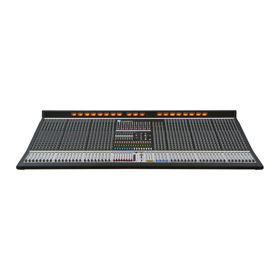
ML5000 Key Features The Allen & Heath ML5000 is a large format VCA equipped dual function live sound console. It can be quickly configured for front-of-house (FOH) or stage monitor mixing. As one console suitable for both applications it is equally well suited to installation, rental and touring. It offers an... -
Page 8: Front Panel Layout
Front Panel Layout ML5000 Service Manual... -
Page 9: Rear Panel Layout
Rear Panel Layout ML5000 Service Manual... -
Page 10: Functional Description
9-16 outputs or matrix 1-8 pre/post auxes but would not normally be required. levels according to the setting of the meter select switch near section. ML5000 Service Manual... -
Page 11: Installing The Console
24 Channel sidecar 45 kg (95 lbs) MPS14 psu 6 kg (13 lbs) HEADPHONES SOCKETS LAMP SOCKETS UNDER ARMREST ML5000-24SC = 831 ML5000-32 = 1596 ML5000-40 = 1851 ML5000-48 = 2106 482.6 Refer to the power supply user guide for safety and installation instructions. -
Page 12: The Expander Sidecar
AL4155 Connecting the Sidecar to the Console Diagram 1 shows the cable routing for connecting the sidecars to the ML5000. Refer to Diagram 2 for connecting one sidecar. Refer to Diagram 3 for connecting two sidecars. Connect the three audio OUTPUT connectors 1 to the main console EXPANDER INPUT using the three 37way 1 to 1 shielded cables provided. - Page 13 EQ IN CONNECTING TWO SIDECARS Diagram 3 9-10 ST EREO MAIN CONSOLE ML5000 11- 12 ST EREO INPUT LOGIC POWER 13- 14 ST EREO 15- 16 ST EREO MAIN BLEND MUTE SAF E/ EDIT PAFL G RO UP ML5000 Service Manual...
- Page 14 A rear panel RS232 port is provided. This is used for loading new operating software into the sidecar from a PC. It is not used for any other function. Check our Web site www.allen-heath.com for details on the latest version of ML5000 operating software and instructions on loading it into the console.
-
Page 15: The Mps14 Power Supply
The MPS14 has audio 0V and mains earth connected internally. If a ground loop is formed operation of the ground lift switch on the rear panel of the MPS14 may improve the situation. ML5000 Service Manual... - Page 16 3.5 inches Depth: 260mm 10.25 inches Weight: 13 pounds Cable Assemblies Assembly Description A&H Part no: DC cable 002-583 2.9m MPS14 to ML5000 console cable assembly DC LINK cable 0.5m MPS14 to MPS14 PSU “LINKING” cable assembly 002-584 ML5000 Service Manual...
-
Page 17: Technical Specifications
ML5000 Technical Specifications 0dBu = 0.775 Vrms, +4dBu = 1.23 Vrms Channel Filters Slope ..........12dB/oct high pass Operating Levels Frequency ........20Hz to 400Hz Channels ......... 0dBu Headroom +21dB variable Mix ..........-2dBu Headroom +23dB Mono Equaliser Frequency Response Referred to 1kHz at +4dBu HF.... -
Page 18: System Block Diagram
FOR EITHER AUX OR GROUP OSC/NOISE/TALKBACK INTERCOM TRIM OSC/NOISE TO TB SIDETONE LISTEN TALK TO INTERCOM PINK NOISE TRIM +48V TO PHONES TRIM TALK TO TB LAMP INTERCOM IN/OUT 1kHz OSC CALL TB MIC MONITOR DIM Disable MONITOR DIM ML5000 Service Manual... - Page 19 METERS 9-16 R AFL MIX GRP/AUX R AFL MATRIX C METERS METER SELECT MONITOR SOURCE FROM INTERCOM PHONES WEDGE MON HEADPHONES TRIM 2TRK TB DIM MONO 2TRK LOCAL MUTE LOCAL MONITOR INPUT PAFL OUTPUT AFL PAFL LOGIC ML5000 Service Manual...
-
Page 20: Connector Types And Wiring
Connector Types and Wiring ML5000 Service Manual... -
Page 21: Gain Structure
‘-10’ to ‘0’ for loudest average volume required. This allows plenty of additional headroom Using the Meters. The ML5000 provides metering if you need it. If you are connecting to crossovers at all important stages through the signal chain. For... -
Page 22: Internal Jumper Options
ROTARY MASTER AUX1>DIR POST-FADE DIR OUT SOURCE PRE-FADE POST-EQ PRE-EQ PRE-FADE SOURCE PRE-INSERT POST-MUTE PRE-FADE MUTE PRE-MUTE CONNECTORS STEREO CHANNEL FADER POST-EQ PRE-FADE SOURCE RIGHT PRE-EQ R POST-EQ PRE-FADE SOURCE LEFT PRE-EQ L POST-MUTE PRE-FADE MUTE PRE-MUTE CONNECTORS ML5000 Service Manual... -
Page 23: Midi
F0 00 20 18 7F 20 tx_event F7 dbx Drive Rack F0 00 01 1E 7F 7F 20 tx_event F7 These messages are subject to further development and addition. Please check the Allen & Heath Web site for the latest information. ML5000 Service Manual... -
Page 24: Archiving The Console Settings
Transmit and Receive. The format for a single at a later date, for example a re-run of a previous packet is as follows: performance. You can also use the dump facility to program additional ML5000 consoles, for example <SysEx header> <packet type>... -
Page 25: Operating Software Technical Support
Allen & Heath or your (SHIFT) appointed service agent. Technical support is available through your dealer or by visiting the Allen & Heath Internet Web site. www.allen-heath.com ML5000 Service Manual... -
Page 26: Servicing The Input Faders
IDC wireforms. The fader panel assembly can now be removed from the console. fig.1 Flip the fader panel over and remove the 2x 4ABx5/16 Countersunk Pozi Black Screws (D) from the Fader Slave PCB (see fig.2) fig.2 ML5000 Service Manual... - Page 27 Note: A fader can be removed without removing the IDC wireforms and Slave PCB. Fader Slave PCB Fader Wireform fig.3 To refit any of the PCB/Fader assemblies, follow the above procedure in reverse order. Ensure all connectors and harnesses are correctly aligned and plugged on. Test for correct operation. ML5000 Service Manual...
-
Page 28: Servicing The Master Faders
Flip the fader panel over to reveal the PCB assemblies (see fig.5). Stereo Fader PCBs VCA Master Fader PCBs Master Fader Centre PCB Master Fader L/R PCBs Control Panel PCB Mute Group PCB VCA Master Slave PCB Stereo Slave PCB fig.5 ML5000 Service Manual... - Page 29 Note: A fader can be removed without removing the IDC wireforms and Slave PCB. To refit any of the PCB assemblies, follow the above procedure in reverse order. Make sure all harnesses are aligned and plugged on. Test for correct operation. ML5000 Service Manual...
-
Page 30: Base Removal And Internal Assemblies
MONO INPUT PCBS SYS-LINK II OUT PCB MIDI POWER STEREO PCBs AUX, GROUP & LRC PCBs MASTER DISTRIBUTION EARTH BUSS PCBS MONO INPUT PCBs MONO INPUT CONNECTOR PCBs Note that the Earth Strip has been removed for clarity. ML5000 Service Manual... -
Page 31: Removing A Mono Input Assembly
The required Mono Input PCB can now be removed from the console. To refit a Mono Input PCB assembly, follow the above procedure in reverse order. Make sure all harnesses are correctly aligned and plugged on. Test for correct operation. ML5000 Service Manual... -
Page 32: Removing The Master Distribution
Use an inspection mirror to check that each connector and IDC harness is correctly aligned and plugged on. Note: If a switch is fitted to the rear of the Master Distribution PCB rather than solder links then make sure that it is set correctly. Test for correct operation. ML5000 Service Manual... -
Page 33: Servicing The Meterbridge
The complete meter panel assembly can now be removed from the meter pod extrusion by pulling it away from the extrusion, bottom first (see fig.9), allowing access to the Meter PCB assemblies. Remove the two attaching IDC harnesses. fig.9 ML5000 Service Manual... -
Page 34: Servicing The Mps14 Power Supply
ONLY, AS INDICATED ON THE UNIT AC~ mains input voltage Fuse type 100V – 230V ± 10% T 5A 250V 20mm In the event of repeated failure of the mains fuse, consult the local dealer from where the unit was purchased. ML5000 Service Manual... -
Page 35: Ordering Consoles And Accessories
User Guide AP3898 MPS14 POWER SUPPLY SERVICE TOOLS The tools required to service the ML5000 are standard to an electronics service workshop and are easily obtainable. The following items are necessary for disassembly and service access: TOOL ORDER CODE 4mm Hexagon (Allen) key... -
Page 36: Ordering Assemblies
ORDERING AN ASSEMBLY The following assemblies for the ML5000 are supplied fully tested. Please quote the description and order code for the part required. Printed circuit board (PCB) assemblies: DESCRIPTION ORDER CODE Mono Input PCB assembly 002-529 Stereo Input PCB assembly... - Page 37 ML5-40/48 Left harness AL3834 ML5-48 Right harness AL3835 THE CHASSIS TRIM ORDER CODE DESCRIPTION ML5000 (all formats) Left & Right Chassis side trims AA3773-L/R Left & Right Moulded side trims AA3781-L/R Write-on strip 10’ AK0327 Ident strip Master Rear AK3788...
-
Page 38: Ordering Spare Parts
It is recommended that the spares kit order code 002-533 is held and maintained by the service agent to enable in-field service repairs to the ML5000 independent of the ALLEN & HEATH factory. Commonly available items such as resistors, capacitors, tools and soldering equipment are not included. - Page 39 Jack Socket ¼” Stereo Switched AL3410 LEDs and Semiconductors: Transistor BC549 NPN AE0020 IC TLO72 Op-Amp AE0046 Transistor J111N FET T092 AE0083 LED 3mm T1 Yellow AE0084 LED 3mm T1 Green AE0085 LED 3mm T1 Red AE0086 ML5000 Service Manual...
- Page 40 Preset 10K Carbon Horizontal Mini AC0250 Preset 470K Carbon Horizontal Adjust AC4012 Meter bulb AD0013 VU Meter + 8V Bulb AD3321 Flex Cable 12 Way 90mm AH2228 Flex Cable 15 Way 90mm AH4091 Battery 2.4V 70mAh NICAD AP3334 ML5000 Service Manual...
-
Page 41: Power Supply
IC Op-Amp NE5532N AE0221 Zener Diode BZX55C2V7 AE0231 Zener Diode BZX79C 12V 400mW AE0232 IC Regulator 7818 AE3155 Diode BYW81P-200 15A AE3468 Diode BYV27-400 2A AE3469 Diode BYV26E 1A 1000V AE3470 Diode P6KE200A AE3471 Transistor Mosfet STP4NA80FP AE3472 ML5000 Service Manual... - Page 42 AL8057 Inductor 4.7uH 600mA AM3467 Fan 80x80x25 12V DC AM3517 Inductor Ferrite Sleeve AM3657 Inductor 5MH 5A CMC AM3900 Inductor 330UH 1A AM3901 Inductor 150UH AM3902 Inductor 10UH AM3903 Inductor 1MH AM3904 Transformer HF Pulse PCB AM4006 ML5000 Service Manual...
-
Page 43: Channel Cue Sheet (Blank)
BLEND BLEND BLEND BLEND BLEND MUTE MUTE MUTE MUTE MUTE MUTE MUTE MUTE SAFE/EDIT SAFE/EDIT SAFE/EDIT SAFE/EDIT SAFE/EDIT SAFE/EDIT SAFE/EDIT SAFE/EDIT PAFL PAFL PAFL PAFL PAFL PAFL PAFL PAFL GROUP GROUP GROUP GROUP GROUP GROUP GROUP GROUP ML5000 Service Manual... -
Page 44: Master Cue Sheet (Blank)
Master Cue Sheet ML5000 Service Manual... -
Page 45: Service Notes (Blank)
Service Notes: ML5000 Service Manual... - Page 46 Drawing Contents METERPOD INTERNAL VIEW System Block Diagram ....D1 Mono Input Channel ....D2-5 METER PANEL FOLDED FORWARD Mono Input Connector....D6-7 4M / 4S Connector ....D8-12 Mono Input Fader ....D13-14 MONO INPUT FADER INTERNAL VIEW MASTER FADER INTERNAL VIEW Mono Input Fader Slave ..D15-16 D63 x 3 Stereo Input Channel ...D17-20 D63 x 8...
- Page 47 ML5000 BLOCK DIAGRAM PAFL PAFL LOGIC FADER GRP/AUX 1-16 MONO CHANNEL AFL LOGIC VCA GROUPS TB ENABLE METER MATRIX METER L AFL MUTE PEAK FADER PEAK EXT IN MUTE MUTE GROUPS L AFL mode SNAPSHOTS R AFL +48V GAIN INSERT...
- Page 55 DSS306 XLR NC3FAV20 DSS306 P13_1 P14_1 PIN-SOLDER 1.2MM PIN-SOLDER 1.2MM PIN-SOLDER 1.2MM PIN-SOLDER 1.2MM ALLEN&HEATH ISSUE DATE ML5000 4SM CONN PCB TITLE: 18-04-02 Kernick Industrial Estate, 02-05-02 Penryn, Cornwall, PAGE: England. TR10 9LU Tel: +44 (0)8707 556250 C4845 DRG No:...
- Page 56 DSS306 P13_2 P14_2 PIN-SOLDER 1.2MM PIN-SOLDER 1.2MM P13_3 P14_3 PIN-SOLDER 1.2MM PIN-SOLDER 1.2MM ALLEN&HEATH ISSUE DATE ML5000 4SM CONN PCB TITLE: 18-04-02 Kernick Industrial Estate, 02-05-02 Penryn, Cornwall, PAGE: England. TR10 9LU Tel: +44 (0)8707 556250 C4845 DRG No: ISSUE:...
- Page 57 PIN-SOLDER 1.2MM PIN-SOLDER 1.2MM P23_1 P24_1 PIN-SOLDER 1.2MM PIN-SOLDER 1.2MM 100N 100V/MLC 100N 100V/MLC ALLEN&HEATH ISSUE DATE ML5000 4SM CONN PCB TITLE: 18-04-02 Kernick Industrial Estate, 02-05-02 Penryn, Cornwall, PAGE: England. TR10 9LU Tel: +44 (0)8707 556250 C4845 DRG No:...
- Page 58 PIN-SOLDER 1.2MM PIN-SOLDER 1.2MM P23_3 P24_3 PIN-SOLDER 1.2MM PIN-SOLDER 1.2MM 100N 100V/MLC 100N 100V/MLC ALLEN&HEATH ISSUE DATE ML5000 4SM CONN PCB TITLE: 18-04-02 Kernick Industrial Estate, 02-05-02 Penryn, Cornwall, PAGE: England. TR10 9LU Tel: +44 (0)8707 556250 C4845 DRG No:...
- Page 112 LED T1 3MM GREEN +10VA +VMTRA +10VA +10VC 0VA_C MTX_LED RES NF +10VA +10VC +5VA 0VA_A NE5532 SOLDER ASSIG MT1/13 NE5532 +5VA MT13 JS17 MT2/14 V_DIV_REFA MT14 MT3/15 MT15 10/16 MT4/16 MT16 RES NF MT5/9 +VMTRA MT6/10 MT10 NE5532 MT7/11 FLEX SKT 12 WAY 90 DEG MT11 MT8/12...
- Page 113 +10VB +VMTRB +10VB +10VD 0VA_D U10A RES NF +10VB +10VD +5VB 0VA_B U10C NE5532 SOLDER ASSIG MT1/13B NE5532 +5VB MT13 JS18 MT2/14B V_DIV_REFB U10B MT14 MT3/15B MT15 10/16 MT4/16B MT16 RES NF +VMTRB MT5/9B ML3MT1 MT6/10B ML3MT2 FLEX SKT 12 WAY 90 DEG MT7/11B NE5532 ML3MT3...
- Page 115 L_SIG_IN U10B CD4053BCM_1 CD4053BCM_1 MTRL 100R R7 100K AFLL_SIG TL072 IN4148 TL072 TL072 TL072 LM393 LM393 R_SIG_IN U10C METER VU MTRL CD4053BCM_1 CD4053BCM_1 330N MTRR IN4148 NE5532 10/16 PAFL_SIG TL072 U10D METER VU CD4053BCM_1 CD4053BCM_1 ACTIVE_M AFL_DC U10A CD4053BCM_1 C_SIG_IN +VPEAK CD4053BCM_1 LM393...
- Page 116 100K U12D METER_MO METERS=MTX 20K 1% MTX_LED 74LS00 U11A TL072 33/10 U12A 74LS00 8K2 1% U11C TL072 ACTIVE_I PAFL_LED U12B 8K2 1% AFL_LED AFL_DC U11B TL072 33/10 74LS00 20K 1% CALL_LED BIG_YELL U12C METERS=MTX 74LS00 MTX1 MTX2 MTX3 MTX4 MTX5 MTX6 MTX7 MTX8...
- Page 120 560R 4.7UH 220R 1N/MYL 1N/MYL 680R BC549 74HCT02 ALLEN&HEATH ISSUE DATE ML5000 MIDI POWER PCB TITLE: 24-05-01 ISSUE 2 CONVERSION TO PROTEL AND ADDITION OF 10V PROTECTION 30-10-01 ISSUE 2.1 U2 CORRECTED TO MAX3088CPA Kernick Industrial Estate, 21-05-02 ISSUE 3...
- Page 122 MASTER BAS16 VOUT VDAC SIL 3 M STRT 10K 1% 0805 REGULATOR DGND +5VL ML4000 TL072D SMD 100K 1% 0805 ML5000 BAS16 BC848B 7805 10K 1% 0805 SIL 3 M STRT 2K2 1% 0805 +5VADC +17V DGND DGND 1/50_S 9K1 1% 1206...
- Page 123 +5VL SPIOE +5VL SPICSL_L U14F SPIOEL U14G U15E SPISTBL SPILDL_L SPICLKL3 100N_S 10R 0805 VFBA2L 74HC04 VFBA1L 74HC08 74HC04 SPICSM_L VFBA0L SPICLKL2 U14E 10R 0805 U14A 74HC541 74HC04 SPICSR_L 74HC04 U14D U14B SPIOEM 74HC04 SPISTBM U15A SPILDM_L 74HC04 SPICLKM 10R 0805 VFBA2M U14C SPICLK...
- Page 124 L1-8 CONNECTOR L9-16 CONNECTOR L17-24 CONNECTOR +5VL FADEN_L CON1 CON2 CON3 VDAC MF1-8 VDAC MF9-16 VDAC MF17-24 0R0 0805 0R0 0805 +5VADC VFBA0L +5VADC VFBA0L +5VADC VFBA0L MTREN_L VFBA1L VFBA2L VFBA1L VFBA2L VFBA1L VFBA2L MTREN_L FADEN_L MTREN_L FADEN_L MTREN_L FADEN_L DGND VCAWR1-8_L SPICLKL1...
- Page 134 Fax: (44) (0) 1326 365736 Error : A&hlogo.wmf file not found. NO.: C4013 ISSUE: SHEET FILE: G:\Product Directories\ML5000\PCB\ML5KSYSLINK II OUT4013_2.1\SYSLINKOUT.ddb - Documents\AG4013 ISSUE 2.1\C4013_2.1 p2.Sch 13:43:01 3-Dec-2002 DISK: A Division of Error : harman.WMF file not found. Harman International Industries Limited...
- Page 135 Fax: (44) (0) 1326 365736 Error : A&hlogo.wmf file not found. NO.: C4013 ISSUE: SHEET FILE: G:\Product Directories\ML5000\PCB\ML5KSYSLINK II OUT4013_2.1\SYSLINKOUT.ddb - Documents\AG4013 ISSUE 2.1\C4013_2.1 p3.Sch 13:43:02 3-Dec-2002 DISK: A Division of Error : harman.WMF file not found. Harman International Industries Limited...
Need help?
Do you have a question about the ML5000 and is the answer not in the manual?
Questions and answers