Compaq Proliant ML370 User Manual
Hide thumbs
Also See for Proliant ML370:
- Maintenance and service manual (152 pages) ,
- User manual (2 pages) ,
- Safety information manual (204 pages)

Related Manuals for Compaq Proliant ML370


Summary of Contents for Compaq Proliant ML370
- Page 1 ProLiant ML370 Setup and Installation Guide Second Edition (December 1999) Part Number 120137-002 Compaq Computer Corporation...
- Page 2 MERCHANTABILITY, FITNESS FOR PARTICULAR PURPOSE, GOOD TITLE AND AGAINST INFRINGEMENT. This publication contains information protected by copyright. No part of this publication may be photocopied or reproduced in any form without prior written consent from Compaq Computer Corporation. © 1999 Compaq Computer Corporation.
-
Page 3: Table Of Contents
Text Conventions......................xi Symbols in Text......................xii Symbols on Equipment....................xii Rack Stability......................xiii Server Warnings and Precautions ................xiii Getting Help ......................xiv Compaq Technical Support ................xiv Compaq Website....................xiv Compaq Authorized Reseller................xv Chapter 1 Server Features Customer Support ....................1-2 Standard Features..................... 1-3 Processors and System Memory ............... - Page 4 Compaq ProLiant ML370 Setup and Installation Guide Server Features continued Warranty ........................1-7 Pre-Failure Warranty ..................1-7 Insight Manager Alert ..................1-7 Server Configuration and Management ..............1-8 Default Configuration ..................1-8 Compaq SmartStart................... 1-9 Server Management ..................1-9 Compaq Insight Manager..................
- Page 5 Contents v Chapter 3 Installing the Rack Model ProLiant ML370 Rack Warnings and Precautions ................3-3 Server Warnings and Precautions ................3-4 The Optimum Environment ..................3-5 Power Requirements..................3-5 Grounding......................3-5 Temperature Requirements................3-6 Airflow Requirements ..................3-6 Installation Sequence ....................3-6 Unpacking the Rack Server ..................
- Page 6 Compaq ProLiant ML370 Setup and Installation Guide Installing Hardware Options continued Understanding Server Security Provisions............. 4-10 Locating Expansion Board Slots ................4-11 Removing the Riser Board Shipping Bracket ............4-12 Installing an Expansion Board ................4-12 Installing Additional Memory................4-15 Installing Additional Mass Storage Devices ............
- Page 7 Novell Device Drivers from Compaq............. 6-11 Microsoft Windows NT Device Drivers from Compaq........6-12 SCO OpenServer and SCO UnixWare Device Drivers from Compaq ... 6-13 IBM OS/2 Device Drivers from Compaq ............6-15 Sun Solaris Device Drivers from Compaq............6-18 Banyan VINES Device Drivers from Compaq..........
- Page 8 Compaq ProLiant ML370 Setup and Installation Guide Regulatory Compliance Notices continued Federal Communications Commission Notice............A-1 Class A Equipment ..................A-2 Class B Equipment................... A-2 Modifications ....................A-3 Cables ......................A-3 Declaration of Conformity for Products Marked with the FCC Logo (United States Only) ..................
- Page 9 Contents ix Appendix E Switches and Jumpers Setting System Board Switches ................E-1 Processor Configuration Switch Settings (SW1) ............. E-2 System Configuration Switch Settings (SW2 Settings) ........... E-2 NIC Operating Mode ....................E-2 SCSI Device Jumper Settings .................. E-3 Index...
-
Page 11: About This Guide
About This Guide This guide is designed to be used as step-by-step instructions for installation and as a reference for operation, troubleshooting, and future upgrades. Text Conventions This document uses the following conventions to distinguish elements of text: Keys Keys appear in boldface. A plus sign (+) between two keys indicates that they should be pressed simultaneously. -
Page 12: Symbols In Text
Compaq ProLiant ML370 Setup and Installation Guide Symbols in Text These symbols may be found in the text of this guide. They have the following meanings. WARNING: Text set off in this manner indicates that failure to follow directions in the warning could result in bodily harm or loss of life. -
Page 13: Rack Stability
About This Guide xiii Any surface or area of the equipment marked with these symbols indicates the presence of a hot surface or hot component. If this surface is contacted, the potential for injury exists. WARNING: To reduce the risk of injury from a hot component, allow the surface to cool before touching. -
Page 14: Getting Help
. This service is available 24 hours a day, 7 days a week. Outside North America, call the nearest Compaq Technical Support Phone Center. Telephone numbers for worldwide Technical Support Centers are listed on the Compaq website. Access the Compaq website by logging on to the Internet: http://www.compaq.com... -
Page 15: Compaq Authorized Reseller
About This Guide xv Compaq Authorized Reseller For the name of your nearest Compaq authorized reseller: In the United States, call 1-800-345-1518. In Canada, call 1-800-263-5868. Elsewhere, see the Compaq website for locations and telephone numbers. -
Page 16: Server Features
Chapter Server Features This guide provides information on the Compaq ProLiant ML370 tower and rack servers featuring the Intel Pentium III processor and 133-MHz system bus. Compaq ProLiant ML370 servers are business-critical servers that support the following components: Pentium III processors... -
Page 17: Customer Support
1-2 Compaq ProLiant ML370 Setup and Installation Guide Standard chassis configurations for ProLiant ML370 tower and rack servers are shown in the following illustrations. Figure 1-1. Compaq ProLiant ML370 tower server Figure 1-2. Compaq ProLiant ML370 rack server Customer Support Compaq servers are backed by comprehensive and flexible customer support programs. -
Page 18: Standard Features
Server Features 1-3 Standard Features The features described in the following sections are standard on the ProLiant ML370 tower and rack servers, unless otherwise noted. Processors and System Memory Compaq ProLiant ML370 servers support advanced processor and memory features: Single-processor unit with one Pentium III processor and integrated... -
Page 19: Disk Controllers
1-4 Compaq ProLiant ML370 Setup and Installation Guide Disk Controllers Compaq ProLiant ML370 servers include a standard disk controller with the following features: Integrated Dual Channel Wide Ultra2 SCSI Controller on the PCI local bus upgradeable to the Integrated Smart Array Controller... -
Page 20: Network Controller
Server Features 1-5 For information on installing a SCSI hard drive in your ProLiant ML370 server, refer to the documentation on the Documentation CD and the SmartStart Support Software CD shipped with your server. When you configure SCSI drives from the support software provided by the operating system vendor, you must also run the driver support diskettes that shipped with your server to properly configure the SCSI drive controls. -
Page 21: Standard Interfaces
1-6 Compaq ProLiant ML370 Setup and Installation Guide Standard Interfaces ProLiant ML370 servers are equipped with the following standard interfaces: Integrated Dual Channel Wide Ultra2 SCSI Controller on Port 1 (internal and external) and Port 2 (internal only) Serial (2) -
Page 22: Power Supply
When Insight Manager alerts you that a component may be eligible for Pre-Failure Warranty replacement, follow the on-screen instructions or contact a Compaq authorized service provider in your area. A yellow status indicator on the Insight Manager control panel signals that a component is in a degraded condition and recommends that you replace the component in a pre-failure condition. -
Page 23: Server Configuration And Management
1-8 Compaq ProLiant ML370 Setup and Installation Guide Server Configuration and Management Compaq servers offer an extensive set of features and optional tools to support effective server management and configuration: Default Configuration Compaq SmartStart Server Management Compaq Insight Manager Compaq System Configuration Utility... -
Page 24: Compaq Smartstart
Compaq SmartStart SmartStart, stored on the SmartStart and Support Software CD, is the intelligent way to configure your Compaq server with Novell, Microsoft, SCO, and IBM system software. SmartStart uses a step-by-step process to configure the server and to load the system software, thereby achieving a well-integrated server and ensuring maximum dependability and supportability. -
Page 25: Compaq System Configuration Utility
For information about Compaq Insight Manager, refer to the Server Setup and Management Pack shipped with your server. -
Page 26: Automatic Server Recovery-2 (Asr-2)
Out-of-band communication with dedicated external management modem connected to the server For information about the standard Compaq Integrated Remote Console, refer to the Compaq Integrated Remote Console User Guide included on the Documentation CD. Compaq Integrated Management Log The standard Compaq Integrated Management Log (IML) records events and stores them in an easily viewable form. -
Page 27: Compaq Remote Insight Board (Pci Option)
Compaq Remote Insight Board (PCI Option) The Compaq Remote Insight Board PCI option is a PCI-based, single-board computer that is installed to provide remote management of a server, regardless of the state of the host operating system or the host CPU. -
Page 28: Security Features
Diagnostic Tools ProLiant ML370 software and firmware diagnostic tools include: Power-On Self-Test (POST) Diagnostics (DIAGS) ROMPaq utilities to upgrade flash ROMs Automatic Server Recovery-2 (ASR-2) For additional information concerning Compaq diagnostic tools, refer to the Documentation CD shipped with your server. -
Page 29: Front Panel Components
1-14 Compaq ProLiant ML370 Setup and Installation Guide Front Panel Components Tower Model Server The figure below shows front panel components of the tower model server. Figure 1-3. Identifying front panel components of the tower model server Table 1-1 Front Panel Components for the Tower Model Server... -
Page 30: Rack Model Server
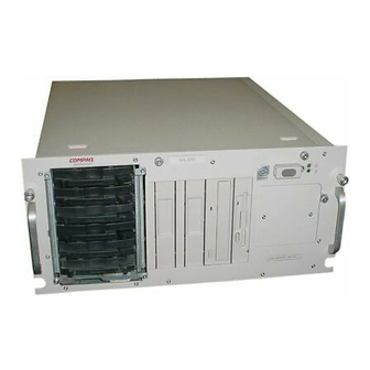
Server Features 1-15 Rack Model Server The figure below shows the front panel components of the rack model server. Figure 1-4 Identifying front panel components of the rack model server Table 1-2 Front Panel Components for the Rack Model Server Number Component Number... -
Page 31: Rear Panel Components
1-16 Compaq ProLiant ML370 Setup and Installation Guide Rear Panel Components Tower Model The figure below shows rear panel components of the tower model. Figure 1-5. Identifying rear panel components of the tower model server Table 1-3 Rear Panel Components for the Tower Model... -
Page 32: Rack Model
Server Features 1-17 Rack Model The figure below shows rear panel components of the rack model server. Figure 1-6. Identifying rear panel components of the rack model server Table 1-4 Rear Panel Components for the Rack Model Server Number Component Number Component Expansion slots... -
Page 33: Network Controller
1-18 Compaq ProLiant ML370 Setup and Installation Guide Network Controller The network interface for ProLiant ML370 server is supported by an RJ-45 connector on the rear panel of the server. The connector features two LED activity indicators located on either side of the tab-lock slot. The LED indicator on the left turns green to indicate network activity. -
Page 34: System Board Components
Server Features 1-19 System Board Components The figure below shows the system board components on ProLiant ML370 servers. The table on the following page provides a list for the location of each component. Figure 1-8. System board components NOTE: Heat sink and processor mounting hardware may appear different than illustrated... - Page 35 1-20 Compaq ProLiant ML370 Setup and Installation Guide Table 1-6 System Board Components Number Component Number Component SCSI port 1 Processor configuration switch–RESERVED SCSI port 2 System configuration switch Integrated Smart Array Processor Power Module Controller slot (PPM) slot 1 (populated)
-
Page 36: Installing The Tower Model Proliant Ml370
Installing the Tower Model ProLiant ML370 The following instructions are provided only as an overview for the first-time installation of your server. If you have any problems, contact your Compaq authorized reseller. Installation Sequence The following sequence should be performed when installing your server for the first time. -
Page 37: Selecting A Site
SmartStart and Support Software CD initialization procedures, refer to the Server Setup and Management pack shipped with your server. 7. Install the Compaq Insight Manager server management functions. For Compaq Management CD initialization procedures, refer to the Server Setup and Management pack shipped with your server. -
Page 38: Unpacking
Installing the Tower Model ProLiant ML370 2-3 WARNING: This equipment is designed for connection to a grounded AC outlet. The grounding type plug is an important safety feature. To reduce risk of electrical shock or damage to your equipment, do not disable this feature. -
Page 39: Installing Expansion Boards And Other Major Hardware Options
See Chapter 4, “Installing Hardware Options,” for instructions on installing PCI expansion boards and other major hardware options. The following major hardware options are available for the ProLiant ML370 server and may be obtained from your local Compaq authorized reseller:... -
Page 40: Connecting The Power Cord And Peripheral Devices
Installing the Tower Model ProLiant ML370 2-5 Connecting the Power Cord and Peripheral Devices After all internal hardware options have been installed in the server, connect the power cord and peripheral devices to the connectors located on the rear panel of the server. Locations of connectors for the power cord and peripheral devices on the rear panel of the server are shown in the figure below. -
Page 41: Power Cords
2-6 Compaq ProLiant ML370 Setup and Installation Guide Power Cords If no power cord was provided with your server, purchase and use a power cord that is approved for use in the country in which the server is to be used. -
Page 42: Configuring The Server With Smartstart
The SmartStart and Support Software CD contains the Compaq System Configuration Utility and ROMPaq. To use the SmartStart and Support Software CD, refer to the Server Setup and Management pack shipped with your server. - Page 43 2-8 Compaq ProLiant ML370 Setup and Installation Guide Assisting in the installation of the operating system Assisting in the running of diagnostic tools such as the TEST and INSPECT utilities The first time the server is configured, the SmartStart program automatically creates a system partition and installs the configuration utility and other Compaq utilities into that partition.
-
Page 44: Using Diagnostic Tools
Server Setup and Management pack for instructions on configuring the system and loading the operating system. To manage the system, refer to the Compaq Management CD provided in the Server Setup and Management pack shipped with your server. Using Diagnostic Tools... -
Page 45: Registering Your Server
2-10 Compaq ProLiant ML370 Setup and Installation Guide Registering Your Server Refer to the Server Setup and Management pack shipped with your server for registration information. You may also register your server online when you visit the Compaq website: http://www.compaq.com... - Page 46 Managing server cabling Accessing the internal components of the rack-mounted server You may choose the optional installation service from Compaq to set up your rack products. Refer to the “Optional Installation Service” section at the end of this chapter for additional information.
- Page 47 Complete rack mounting instructions are available on the Documentation CD shipped with your server. In addition, the Rack Builder Configuration and Rack Information Library information can be found on the Compaq website: http://www.compaq.com The entire Rack Resource CD Kit, part number 298721-001, ships with all Compaq server racks.
-
Page 48: Installing The Rack Model Proliant Ml370
Rack Information Library This information allows you to view, search, and print documentation for Compaq racks and rack options. The information helps you to set up and optimize your new Compaq rack to best fit the needs of your environment. -
Page 49: Server Warnings And Precautions
3-4 Compaq ProLiant ML370 Setup and Installation Guide Server Warnings and Precautions WARNING: This product is very heavy. To reduce the risk of personal injury or damage to the equipment: Remove all pluggable power supplies and modules to reduce 22.6 kg the weight of the product before lifting it. -
Page 50: The Optimum Environment
Installing the Rack Model ProLiant ML370 3-5 The Optimum Environment When installing your Compaq ProLiant ML370 server in a rack, certain power requirements must be met. Power Requirements WARNING: To reduce the risk of personal injury, fire, or damage to the equipment, do not overload the AC supply branch circuit that provides power to the rack. -
Page 51: Temperature Requirements
Airflow Requirements Compaq rack servers draw cool air in through the front door and expel warm air out through the rear. Therefore, the front door of the rack must be adequately ventilated to allow ambient room air to enter the cabinet and the rear door must be adequately ventilated to allow the warm air to escape from the cabinet. -
Page 52: Unpacking The Rack Server
SmartStart program, it automatically starts the System Configuration Utility. 12. Install Compaq Insight Manager to manage the server. 13. Register your server. For server registration information, refer to the Server Setup and Management pack shipped with your server or register online at the Compaq website: http://www.compaq.com... -
Page 53: Locating Materials
3-8 Compaq ProLiant ML370 Setup and Installation Guide Locating Materials All of the rack mounting hardware needed to install the ProLiant ML370 server in the rack is included with the rack and with the server. Figure 3-2. Rack mounting hardware... - Page 54 Installing the Rack Model ProLiant ML370 3-9 Table 3-1 Rack Mounting Hardware Number Item Number Item Rack-mounting brackets Cable management arm 22-inch slide rail Rack mounting template assemblies Cable management arm Miscellaneous screws bracket Cable management arm rack bracket...
- Page 55 3-10 Compaq ProLiant ML370 Setup and Installation Guide Contents of the rack server box include: Power cord Rack mounting hardware: One pair of rack-mounting brackets One pair of 22-inch slide rail assemblies Cable management arm bracket Cable management arm rack bracket...
-
Page 56: Installing Expansion Boards And Other Major Hardware Options
Chapter 4, “Installing Hardware Options,” provides instructions for installing these and other major hardware options. The following major hardware options are available for the ProLiant ML370 server and may be obtained from your local Compaq authorized reseller or Compaq authorized service provider:... - Page 57 3-12 Compaq ProLiant ML370 Setup and Installation Guide Figure 3-3. Rack mounting inner and outer brackets NOTE: To make installation of the mounting bracket easier, attach the bracket rail to the rack mounting bracket before attaching the mounting bracket assembly to the rack. This way, the joined mounting bracket and bracket rail can be fastened to the rack as one assembly.
-
Page 58: Attaching The Bracket Rail To The Mounting Bracket
Installing the Rack Model ProLiant ML370 3-13 Attaching the Bracket Rail to the Mounting Bracket 1. Unpack the hardware mounting kit. 2. Place the two-piece slide rail assembly (outer bracket rail and inner component rail) and fasteners on a flat surface along with the mounting brackets and fasteners that came with the rack. - Page 59 3-14 Compaq ProLiant ML370 Setup and Installation Guide CZR4-006.eps Figure 3-6. Separated bracket rail (top) and component rail The bracket rail consists of a fixed outer rail that screws to the rack-mounting bracket, and an inner slide on a steel ball bearing movement. The inner slide does not detach from its housing.
- Page 60 Installing the Rack Model ProLiant ML370 3-15 The front of the bracket rail allows the inner slide to move forward on ball bearings. 7. Extend the inner slide from the front of the bracket rail. With the inner slide extended, you will see two screw holes aligned in the mounting bracket and the bracket rail.
-
Page 61: Attaching The Slide Assembly To The Rack
The screws line up with the 22-inch markings stamped along one edge of the mounting bracket. These marks identify the mounting holes for the 22-inch slides used in Compaq racks. The 24-inch markings stamped along the other edge are for use with the 24-inch slides that support other components. - Page 62 Installing the Rack Model ProLiant ML370 3-17 1. Starting at the bottom of the rack, or at the top of a previously mounted component, measure the screw hole locations for the server’s mounting bracket assemblies. 2. Use a pencil to mark the screw hole locations on the outside of the rack.
-
Page 63: Inserting Cage Nuts Into The Rack Frame
3-18 Compaq ProLiant ML370 Setup and Installation Guide Inserting Cage Nuts into the Rack Frame After marking the positions for the fasteners in both the front and back of the rack, use the fitting tool to insert cage nuts on the inside of the rails at the marked locations. - Page 64 Installing the Rack Model ProLiant ML370 3-19 CZR4-011.eps Figure 3-11. Attaching mounting bracket assembly to the front of the rack 2. Carefully align the mounting bracket assembly with the rear rack frame. 3. Secure the back end of the mounting bracket assembly to the back corner brace of the rack with one M6 x 1.0-12L Phillips screw through...
-
Page 65: Attaching Component Rails To The Server
3-20 Compaq ProLiant ML370 Setup and Installation Guide Attaching Component Rails to the Server 1. Place the tab on a component rail at the front of the server chassis. The holes in the component rail line up only one way with the chassis. -
Page 66: Loading The Rack Server
Installing the Rack Model ProLiant ML370 3-21 Figure 3-14. Attaching a cable management arm bracket to the server Loading the Rack Server When mounting multiple servers, only install one set of mounting brackets at a time. Make sure that the brackets align perfectly, the server fits in the rack, and the faceplate fits securely with thumbscrews. - Page 67 3-22 Compaq ProLiant ML370 Setup and Installation Guide Use the following procedure to mount and secure your server in the rack: 1. Pull the slide rails forward until they are fully extended from the mounting brackets. At full extension, the rails lock into place, as shown in the following figure.
- Page 68 Installing the Rack Model ProLiant ML370 3-23 2. Carefully align the server component rails with the rack slide rails, as shown in the following figure. Figure 3-16. Aligning the server component rails with the rack rails 3. Ensure that the server component rails are fully engaged into the plastic guides and bearings on the rack rails on both sides, then slowly slide the server into the rack.
- Page 69 3-24 Compaq ProLiant ML370 Setup and Installation Guide 4. Press the component rail release latches inward on both sides of the server, and continue to slide the server into the rack. Figure 3-17. Loading the server into the rack 5. Position the server in the rack, as shown in the following figure.
-
Page 70: Attaching The Cable Management Arm
Installing the Rack Model ProLiant ML370 3-25 IMPORTANT: When servicing the server, fully extend the component until the latches lock. To return the server to the rack, press the latches and slide the server into the rack. Attaching the Cable Management Arm A double-hinged cable management arm and fasteners are provided with each server. - Page 71 3-26 Compaq ProLiant ML370 Setup and Installation Guide 5. Align the screw-retaining plate on the inside of the rack. 6. Attach the cable management arm to the rack with two 10-32 x 5/8-inch Phillips washer-face, hex-head screws. Figure 3-20. Attaching the cable management arm to the rear brace...
-
Page 72: Attaching The Cable Support
Installing the Rack Model ProLiant ML370 3-27 Attaching the Cable Support The optional cable support connects to both sides of the rear frame of the rack. All cables to and from the server are tied to this support, which allows the server cables to stretch from the right rear of the server across to the cable channel on the other side of the rack. -
Page 73: Connecting The Power Cord And Peripheral Devices
WARNING: To reduce the risk of electrical shock or fire, do not plug telecommunications/telephone connectors into the NIC receptacles. Figure 3-22. Rear panel of the ProLiant ML370 rack server Table 3-2 Rear Panel Connectors on the ProLiant ML370 Rack Server... - Page 74 Installing the Rack Model ProLiant ML370 3-29 Use the following procedure to connect the power cord and peripheral devices: 1. Plug the power cable and other peripheral cables into the server. 2. If you install a switchbox in the rack, route the CPU-to-switchbox cables to the switchbox.
-
Page 75: Power Cords
3-30 Compaq ProLiant ML370 Setup and Installation Guide 5. Extend the bundled cables down through the cable channel on the rack. NOTE: Before loading a second component, be sure to secure the server to the rack with the faceplate thumbscrews. -
Page 76: Powering Up The Server
Installing the Rack Model ProLiant ML370 3-31 Powering Up the Server After the cables have been connected to the server, you are ready to power up the server. WARNING: To reduce the risk of electric shock or damage to the equipment: Do not disable the power cord grounding plug. -
Page 77: Configuring The Server With Smartstart
The SmartStart and Support Software CD contains the Compaq System Configuration Utility and ROMPaq. Refer to the Server Setup and Management pack shipped with the server for instructions on using the SmartStart and Support Software CD. -
Page 78: Using Diagnostic Tools
SmartStart documentation included with your Server Setup and Management pack to configure the system and load the operating system. Refer to the Compaq Management for additional information on server management and SmartStart utilities. Using Diagnostic Tools ProLiant ML370 software and firmware diagnostic tools include:... -
Page 79: Registering Your Server
Service may be ordered from a Compaq authorized reseller or, in North America only, call 1-800-OK-COMPAQ. In the United States, Compaq will make all of the arrangements to have the rack system installed by qualified Guaranteed Service Providers. An order form... -
Page 80: Installing Hardware Options
For complete hardware option installation instructions, refer to the installation documentation that came with the option kit. For an illustrated overview of installing many Compaq option upgrades, refer to the hardware installation and configuration poster shipped with your server, or to the installation labels located on the inside of the large and small access panels. - Page 81 4-2 Compaq ProLiant ML370 Setup and Installation Guide Table 4-1 Gaining Access to Internal Components continued Component Access Front of media drive bays Open the front bezel* Internal SCSI cables Open the front bezel* and remove both the large and small access panel Internal SCSI connectors (ports 1 &...
-
Page 82: Differences Between The Tower And Rack Model Servers
Differences Between the Tower and Rack Model Servers The major difference between the Compaq ProLiant ML370 tower and rack models is the chassis configuration. The tower model can be mounted in a rack, however, with the Tower-to-Rack Conversion Option Kit. The tower model also has feet on the bottom of the server and a front bezel to cover the server chassis. -
Page 83: Opening The Front Bezel
4-4 Compaq ProLiant ML370 Setup and Installation Guide Opening the Front Bezel This procedure applies only to tower models because the rack model does not have a front bezel. To open the front bezel of the tower model: 1. Turn the key lock to release, if locked. -
Page 84: Removing The Small Access Panel
1. If the computer is on, turn it off and disconnect the power cord. IMPORTANT: The system power in the ProLiant ML370 server does not completely shut off from the front panel power On/Standby switch. Moving the switch from On to Standby leaves some portions of the power supply and some internal circuitry active. - Page 85 4-6 Compaq ProLiant ML370 Setup and Installation Guide 4. Loosen the top thumbscrew. 5. Slide the small access panel toward the rear of the unit about 0.5-inch (1.5 cm), and move the panel off to the side of the server.
-
Page 86: Rack Model
Installing Hardware Options 4-7 Rack Model Remove the small access panel: 1. Loosen the front panel thumbscrews to release the server from the rack as shown in the figure below. Figure 4-5. Removing the small access panel (rack server) 2. If the server is in the rack, pull the server out from the rack to the locked position. -
Page 87: Tower Model
4-8 Compaq ProLiant ML370 Setup and Installation Guide Tower Model Remove the large access panel: 1. If the server is on, turn it off and disconnect the power cord. 2. Disconnect any other external equipment connected to the computer. 3. Open the front bezel. -
Page 88: Installing Hardware Options
Installing Hardware Options 4-9 3. Loosen the front panel thumbscrews to release the server from the rack. 4. Pull the server out from the rack to the locked position. 5. Loosen the two thumbscrews located on the front panel of the server. 6. -
Page 89: Understanding Server Security Provisions
4-10 Compaq ProLiant ML370 Setup and Installation Guide Understanding Server Security Provisions The tower model is equipped with unique security access provisions, including one key lock for the front bezel. To secure the tower chassis, close the front bezel and turn the key lock shown in the figure below to lock the bezel. -
Page 90: Locating Expansion Board Slots
Installing Hardware Options 4-11 Locating Expansion Board Slots The server has six PCI expansion slots located directly beneath the small access panel: Two 32-bit PCI slots (1 and 2) Four 64-bit PCI slots (3 through 6) Expansion boards can be installed in the locations shown in the figure below. NOTE: The rack model slot configuration is oriented differently than the tower model shown below. -
Page 91: Removing The Riser Board Shipping Bracket
4-12 Compaq ProLiant ML370 Setup and Installation Guide Removing the Riser Board Shipping Bracket Some ProLiant ML370 servers are packaged with a shipping bracket for greater stability in the area of the riser board. Before installing an expansion board, remove the shipping bracket: 1. - Page 92 Installing Hardware Options 4-13 For an illustration overview of the procedure, refer either to the Hardware Installation and Configuration poster shipped with your server or to the expansion board installation label located on the inside of the small access panel. NOTE: If your server contains a shipping bracket, you must remove the bracket before installing the expansion board.
- Page 93 4-14 Compaq ProLiant ML370 Setup and Installation Guide 6. Insert the expansion board into one of the slots. Figure 4-12. Inserting the expansion board 7. Close the expansion slot latch to secure the board. Figure 4-13. Securing the expansion board 8.
-
Page 94: Installing Additional Memory
133-MHz registered SDRAM. The DIMM sockets may be populated in any order. CAUTION: Use only Compaq SDRAM modules. SDRAM from other sources may adversely affect data integrity. To install more memory, refer to one of the following installation sources: For a text and illustrated procedure, refer to the installation documentation that came with the option kit. - Page 95 4-16 Compaq ProLiant ML370 Setup and Installation Guide 6. Open the slot latches and insert the module into the socket Figure 4-14. Installing a memory module on the system board NOTE: Memory modules can be installed only in one direction. Match the notch on the module with the tab on the DIMM socket.
-
Page 96: Installing Additional Mass Storage Devices
Installing Hardware Options 4-17 Installing Additional Mass Storage Devices The server is shipped standard with a total of 10 drive bays for installing additional internal mass storage devices. Non-SCSI devices including CD-ROM drives and SCSI devices such as tape or hard drives can be installed in the vacant non-hot-plug, removable media drive bays. -
Page 97: Scsi Hard Drive Installation Guidelines
The SCSI ID for each hot-plug hard drive is automatically set as the bay number (Bay 0 = SCSI ID 0). Except for hot-plug drives in ProLiant ML370 servers and storage systems, you must manually set the SCSI ID on each drive to a unique value in the range of 0 to 6 for each SCSI bus. - Page 98 Installing Hardware Options 4-19 the installation documentation that came with the drive. Also, see Chapter 5, “SCSI Cabling Instructions,” for SCSI cabling information. The figures below provide only an overview of removing the blank panel and installing a storage device. The rack model will be slightly different from the tower model shown in the following illustrations.
- Page 99 4-20 Compaq ProLiant ML370 Setup and Installation Guide Figure 4-17. Installing a hard drive in the removable media area...
-
Page 100: Installing A Half-Height Device
NOTE: Some half-height devices require an additional tray or bay adapter for installation. Order trays or other adapters from your Compaq authorized reseller. Figure 4-18. Installing a half-height tape drive in the removable media area 3. -
Page 101: Installing A Full-Height Device
4-22 Compaq ProLiant ML370 Setup and Installation Guide Installing a Full-Height Device Install a full-height such as a DLT tape drive in the removable media bay: 1. Unscrew and remove both bay blanks. 2. Slide the tape drive into the fully open bay, as shown in the following illustration. -
Page 102: Installing Hard Drives In The Hot-Plug Drive Cage
Installing Hardware Options 4-23 Installing Hard Drives in the Hot-Plug Drive Cage To install a hot-plug hard drive, first review the installation documentation that came with the drive. The following illustrations provide only an overview of a hard drive installation. The rack model will be slightly different from the tower model shown below. -
Page 103: Installing External Storage Devices
“SCSI Cabling Instructions,” for additional server cabling information. The following illustration provides only an overview of this installation procedure. The ProLiant ML370 rack configuration is different from the ProLiant ML370 tower model shown below. CAUTION: External SCSI port 1 and internal SCSI port 1 are the same port. -
Page 104: Installing A Second Processor
Installing Hardware Options 4-25 Installing a Second Processor Refer to one of the following processor installation documents: For a text and illustration procedure, refer to the installation documentation that came with the option kit. For a text overview of the procedure, refer to the procedure below. For an illustrated overview of the procedure, refer to the hardware installation and configuration poster shipped with your server or to the configuration label located on the inside of the large access panel. -
Page 105: Installing A Processor Power Module
7. Prepare to install the Processor Power Module. NOTE: When more than one processor is installed in your server, both processors must be running at the same speed. ProLiant ML370 servers do not support mixed processor speeds. Installing a Processor Power Module Every processor supplied by Compaq comes with a Processor Power Module (DC-to-DC converter). - Page 106 Installing Hardware Options 4-27 The PPM is keyed to ensure correct alignment. A notch in the center of the module’s bottom edge must align with a tab in the mounting bracket. 1. Align the key slot in the bottom edge of the PPM with the tab in the expansion slot.
-
Page 107: Replacing The Riser Board And Riser Board Brace
CAUTION: If the riser board or riser board brace needs to be replaced, both must be sent to Compaq as one unit. If they are sent separately, all warranties are voided for these components. Installing the Riser Board and Riser Board Brace 1. - Page 108 Installing Hardware Options 4-29 Figure 4-25. Removing the riser board and brace assembly 7. Install the new riser board and riser board brace assembly by aligning the contact end of the riser board with the riser board slot on the system board and pressing until the board fits snugly in the slot.
-
Page 109: Integrated Smart Array Controller Option
4-30 Compaq ProLiant ML370 Setup and Installation Guide 11. Slide the rack model server back into the rack and use the thumbscrews to secure the server. 12. Reconnect power cords and turn the server on. Integrated Smart Array Controller Option... - Page 110 Installing Hardware Options 4-31 4. Locate the Integrated Smart Array Controller slot on the system board, as shown in the following figure. Figure 4-27. Locating the Integrated Smart Array Controller on the system board 5. Insert the tab end of the controller into the slot at an angle , as shown in the following figure.
-
Page 111: Board Layouts
9. Restore any data that was backed up from the server before the controller was installed. For information on configuring the Integrated Smart Array Controller, refer either to the documentation that shipped with the option kit or to the Compaq Integrated Smart Array Controller User Guide. Board Layouts... - Page 112 Installing Hardware Options 4-33 Figure 4-29. Locating slots on the riser board Table 4-3 Riser Board Components Number Component Primary PCI bus slot 1 (32-bit) Primary PCI bus slot 2 (32-bit) Secondary PCI bus slot 3 (64-bit) Secondary PCI bus slot 4 (64-bit) Secondary PCI bus slot 5 (64-bit) Secondary PCI bus slot 6 (64-bit)
-
Page 113: System Board Components
5 - Off Password disable 6 - Off Maintenance Note: When the system setting is OFF, the function is disabled. System Board Components The figure below illustrates the system board components on ProLiant ML370 servers. Figure 4-30. System board components... - Page 114 Installing Hardware Options 4-35 NOTE: Heat sink and processor mounting hardware may appear different than illustrated. Table 4-5 System Board Components Number Component Number Component SCSI port 1 Processor configuration switch–RESERVED SCSI port 2 System configuration switch Integrated Smart Array Processor Power Module Controller slot slot 1 (populated)
-
Page 115: Scsi Cabling Instructions
Internal removable media area Internal hot-plug hard drive cage External storage devices All of the required SCSI cabling equipment you need to install Compaq mass storage devices is shipped with your server or with the SCSI storage device option kits. -
Page 116: Scsi Cabling Equipment
5-2 Compaq ProLiant ML370 Setup and Installation Guide SCSI Cabling Equipment ProLiant ML370 servers are shipped with two preinstalled SCSI cables to connect hard drives and removable media devices to an Integrated Dual Channel Wide Ultra2 SCSI Controller port on the system board. The default... -
Page 117: Point-To-Point Scsi Cable From Scsi Port 2 To The Hot-Plug Hard Drive Cage
Integrated Dual Channel Wide Ultra2 SCSI Controller, an adapter is required to link the SCSI cable with the Fast-SCSI-2 device. This adapter is included in all Compaq option kits containing narrow SCSI devices. To purchase an adapter for use with any third-party option, order the Wide-to-Standard SCSI Cable Adapter Option Kit from your local Compaq authorized reseller or Compaq authorized service provider. -
Page 118: Scsi Device Installation Guidelines
5-4 Compaq ProLiant ML370 Setup and Installation Guide SCSI Device Installation Guidelines The following guidelines apply for adding SCSI devices: The SCSI ID for each hot-plug hard drive is set as the bay number (Bay 0 = SCSI ID 0). -
Page 119: Internal Scsi Cabling For The Integrated Dual Channel Wide Ultra2 Scsi Controller
Integrated Dual Channel Wide Ultra2 SCSI Controller or a Wide-SCSI controller board. Order the adapter kit from your Compaq authorized reseller. 6. Is the internal SCSI mass storage device a non-hot-plug device? If yes, the device can only be installed in the removable media area. - Page 120 5-6 Compaq ProLiant ML370 Setup and Installation Guide Figure 5-3. Default cabling configuration In the factory configuration, the server is ready for the installation of hot-plug hard drives in the hard drive cage. The server sets SCSI IDs automatically and no additional cables are required.
-
Page 121: Connecting An Array Controller To Hot-Plug Drives
Hot-Plug Drives Connecting a Controller Board to the Hot-Plug Drive Cage ProLiant ML370 servers use an integrated SCSI array controller to run hard drives and other system resources. The following adapter and controllers are available from Compaq authorized resellers: Smart Array 221 Controller... - Page 122 5-8 Compaq ProLiant ML370 Setup and Installation Guide Connect the array controller to the hard drive cage as shown in the figure below: 1. Disconnect the point-to-point SCSI cable from SCSI port 2. 2. Connect the controller end of the point-to-point SCSI cable to a SCSI connector on the controller board.
-
Page 123: Connecting The Controller Board To Removable Media Devices
SCSI Cabling Instructions 5-9 Connecting the Controller Board to Removable Media Devices Controller boards can be connected to removable media devices directly with the three-device, terminated SCSI cable provided with your server. The figure below shows a controller cabled to a device in the removable media area. Connect the controller to the removable media area: 1. -
Page 124: Running Internal And External Drives
5-10 Compaq ProLiant ML370 Setup and Installation Guide Running Internal and External Drives Optional mass storage SCSI devices such as Compaq ProLiant Storage Systems can be connected to the server by using the external SCSI connector on the back of the unit. To connect to an external storage device as shown below, refer to the installation documentation provided with the external storage device. -
Page 125: Integrated Smart Array Controller
SCSI Cabling Instructions 5-11 The figure below shows the SCSI connection of the ProLiant ML370 server to an external storage system. Figure 5-7. Connecting the external SCSI connector to a storage device The external SCSI connector on the rear panel of the server is dedicated for use with external SCSI devices only, and the internal SCSI port 1 connector is dedicated for use with internal SCSI devices only. - Page 126 5-12 Compaq ProLiant ML370 Setup and Installation Guide The controller supports the following features. 16 MB total memory, 8 MB read-ahead cache Support for up to six internal Wide Ultra2 SCSI hot-plug drives in RAID 0, 1, 0+1, and 5...
- Page 127 SCSI Cabling Instructions 5-13 SCSI port 2 is dedicated to controlling the SCSI drives in the internal drive bay. Port 1 connects to an external SCSI connector or to an internal removable storage device, but not both at the same time. For instructions on installing the controller, refer to the instructions provided in Chapter 4, “Installing Hardware Options,”...
-
Page 128: Server Configuration And Utilities
Chapter Server Configuration and Utilities This chapter provides instructions for using Compaq System Configuration Utilities, for using Compaq SmartStart, and for loading device drivers. System Configuration Utility Compaq System Configuration Utility performs a wide range of configuration activities, including: Automatically configuring PCI plug-and-play boards... -
Page 129: Resolving Resource Conflicts
6-2 Compaq ProLiant ML370 Setup and Installation Guide IMPORTANT: The Compaq utilities partition should not be confused with the partitions created by your operating system. In ProLiant ML370 servers, the system ROM automatically configures the system when adding or removing memory, a second processor, or a PCI expansion board. -
Page 130: Starting The System Configuration Utility
The first time you start the Compaq System Configuration Utility, follow the procedure on the Compaq SmartStart installation poster. After the Compaq SmartStart and Support Software CD is used for the first time to create and populate the system configuration partition, you may access the System Configuration Utility as follows: 1. -
Page 131: System Configuration Menu
6-4 Compaq ProLiant ML370 Setup and Installation Guide System Configuration Menu The following options are available from the System Configuration Utility menu: Hardware configuration Drive array configuration Power-On defaults System configuration partition Configuration backup Return to the previous menu Configuring Hardware After the Configure Hardware menu, a screen with five steps is displayed. -
Page 132: System Configuration Partition
Server Configuration and Utilities 6-5 Drive Array Configuration This option runs the Compaq Array Configuration Utility. This utility allows you to view and make changes to array controller configurations. Power-On Defaults You can set and change the Power-On features at any time. -
Page 133: Creating A New System Configuration Partition
6-6 Compaq ProLiant ML370 Setup and Installation Guide Creating a New System Configuration Partition If you used SmartStart to configure your server initially, a new Compaq utility partition was created automatically. If SmartStart was not used for initial server configuration, follow the procedure below to create a system configuration partition: 1. -
Page 134: Configuration Backup
Server Configuration and Utilities 6-7 Configuration Backup The Configuration Backup option allows you to create a backup of the system configuration and to restore the system configuration from the backup. The following menu options are available: Backup Restore Configuration Backup and Configuration History Files When you save and exit the System Configuration Utility, the utility retains a history of the configuration. -
Page 135: Configuring Pci Boards Automatically
6-8 Compaq ProLiant ML370 Setup and Installation Guide Table 6-1 System Configuration History Files continued Filename Description SYSTEM1.CHL Textual representation of SYSTEM1.SCI file SYSTEM2.CHL Textual representation of SYSTEM2.SCI file (oldest) IMPORTANT: If there is not enough disk space for the entire system configuration history log, the utility deletes log files starting with the oldest files (SYSTEM2.SCI and... -
Page 136: Installing An Operating System
Server Configuration and Utilities 6-9 Installing an Operating System Single Processor Operating Support Compaq ProLiant ML370 servers support the following operating systems: Novell NetWare 3.2, 4.2, and 5.0 NetWare for Small Business 4.2 and 5.0 Microsoft Windows NT Server 3.51 and 4.0 Microsoft NT Enterprise 4.0... -
Page 137: Loading Compaq Device Drivers
IBM OS/2 Warp Server for E-Commerce Sun Solaris 2.6 and 7 Intel Platform Edition If you use Compaq SmartStart to install the OS, the appropriate drivers are installed automatically. When you select the Operating System Installation feature from the System Configuration Utility main menu, the utility provides prompts to simplify the installation. -
Page 138: Novell Device Drivers From Compaq
If you use SmartStart to install the operating system, the drivers are installed automatically. Manual Installation Configure the server without using SmartStart: 1. With power to the server off, insert the Compaq SmartStart and Support Software CD into the CD-ROM drive. 2. Start your system. 3. Select Manual Installation. -
Page 139: Microsoft Windows Nt Device Drivers From Compaq
Compaq SmartStart and Support Software CD. The drivers on the NT SSD may be newer versions with support for new functionality, problem fixes, and so on. If you use Compaq SmartStart to install your operating system, these drivers are installed automatically. Otherwise, you can use Compaq SmartStart to create the Compaq SSD for Microsoft Windows NT from Compaq to support a manual installation of NT drivers. -
Page 140: Sco Openserver And Sco Unixware Device Drivers From Compaq
Device Drivers from Compaq If you are using the Compaq NC3163 Fast Ethernet NIC Embedded 10/100 WOL network controller on a ProLiant ML370 server and you do not plan to use the SmartStart installation process to set up your server, you must install updated support software for your controller to connect properly to the network. - Page 141 Support Software CD automatically creates the system configuration partition server and allows you to use the SCO interview process. Depending on your operating system, it may be necessary to use the Compaq Boot Time Loadable Drivers (BTLD) diskette or the Compaq Host Bus Adapters (HBA) diskette along with the Compaq Extended Feature Supplement (EFS) diskette to install driver support.
-
Page 142: Ibm Os/2 Device Drivers From Compaq
IBM OS/2 Device Drivers from Compaq If you are using the Compaq NC3163 Fast Ethernet NIC Embedded 10/100 WOL network controller on a ProLiant ML370 server and you do not plan to use the SmartStart installation process to setup your server, you must install updated support software for your controller to connect properly to the network. - Page 143 6-16 Compaq ProLiant ML370 Setup and Installation Guide Compaq SmartStart Installation If you use Compaq SmartStart to install the OS/2 operating system, the drivers are installed automatically. Manual Installation Install the operating system and configure the server without Compaq SmartStart: 1.
-
Page 144: Sun Solaris Device Drivers From Compaq
Server Configuration and Utilities 6-17 Retail Installation You cannot install IBM OS/2 on a Compaq server using the unmodified installation diskettes that come with the IBM OS/2 retail CD. To install IBM OS/2 on a Compaq server: 1. Create IBM OS/2 SSD diskettes from the Compaq SmartStart and Support Software CD as outlined in the instructions for manual installation. -
Page 145: Diagnostics And Other Utilities
Drivers can also be ordered through SoftPaq and can be downloaded from the Compaq website: http://www.compaq.com Manual Installation 1. With the power off, insert the Compaq SmartStart and Support Software CD into the CD-ROM drive. 2. Start your system. 3. Select Manual Installation. - Page 146 Server Configuration and Utilities 6-19 Controller Naming Conventions Some of the popular operating systems, including Microsoft DOS and Novell NetWare products, are listed in the table below with their corresponding driver names. Table 6-2 Controller Driver Naming Conventions Operating System Driver Type Driver File Name Banyan VINES...
- Page 147 6-20 Compaq ProLiant ML370 Setup and Installation Guide Table 6-2 Controller Driver Naming Conventions continued Operating System Driver Type Driver File Name SCO OpenServer 5 Cnet/cet SCO UnixWare 7 Cnet/cet, n100, n1000c SCO UnixWare 2.1.x DLPI Cnet/cet, n100, n1000c SCO Open Server 3...
-
Page 148: Integrated Management Log
Chapter Integrated Management Log The Compaq Integrated Management Log (IML) records events and stores them in an easily viewable form. The IML records hundreds of events and then marks each event with a time-stamp with one-minute granularity. Events listed in the IML are categorized as one of four event severity levels: Status - Indicates that the message is informational only. -
Page 149: Multiple Ways Of Viewing The Log
From within the Compaq Survey Utility From the Integrated Management Display (optional) Compaq Insight Manager The Compaq Insight Manager is a server management tool that provides in-depth fault, configuration, and performance monitoring of hundreds of Compaq servers from a single management console. System parameters are monitored and describe the status of all key server components to allow you to take immediate action. -
Page 150: Compaq Survey Utility
This information is provided on the Documentation CD in the Server Setup and Management pack and is available on the Compaq website. Refer to the Documentation CD for information on installing and running the Survey Utility. -
Page 151: List Of Events
7-4 Compaq ProLiant ML370 Setup and Installation Guide List of Events The event list displays the affected components and the associated error messages. Though the same basic information is displayed, the format of the list may be different depending on how you are viewing it from within Insight Manager, or from within the Survey Utility. - Page 152 Integrated Management Log 7-5 Table 7-1 Event Messages continued Event Type Event Message POST error POST error: error message Power Subsystem Power supply failure System power supply failure (power supply X) Power supply inserted System power supply inserted (power supply X) Power supply removed System power supply removed (power supply X) Power supply not redundant...
-
Page 153: Regulatory Compliance Notices
Numbers For the purpose of regulatory compliance certifications and identification, your ProLiant ML370 server is assigned a Compaq series number. The Compaq series number for this product is Series ES1008. The series number can be found on the product label, along with the required approval markings and information. -
Page 154: Class A Equipment
A-2 Compaq ProLiant ML370 Setup and Installation Guide devices in both classes to bear a label indicating the interference potential of the device as well as additional operating instructions for the user. The rating label on the device shows which class (A or B) the equipment falls into. -
Page 155: Modifications
Regulatory Compliance Notices A-3 Modifications The FCC requires the user to be notified that any changes or modifications made to this device that are not expressly approved by Compaq Computer Corporation may void the user's authority to operate the equipment. Cables... -
Page 156: Canadian Notice (Avis Canadien
A-4 Compaq ProLiant ML370 Setup and Installation Guide Canadian Notice (Avis Canadien) Class A Equipment This Class A digital apparatus meets all requirements of the Canadian Interference-Causing Equipment Regulations. Cet appareil numérique de la classe A respecte toutes les exigences du Règlement sur le matériel brouilleur du Canada. -
Page 157: Japanese Notice
Regulatory Compliance Notices A-5 Japanese Notice Taiwanese Notice Chinese Notice... -
Page 158: Laser Devices
August 1, 1976. Compliance is mandatory for products marketed in the United States. Compliance with International Regulations All Compaq systems equipped with laser devices comply with appropriate safety standards including IEC 825. Laser Product Label The following label or equivalent is located on the surface of the Compaq supplied laser device. -
Page 159: Laser Information
Your computer is provided with an internal lithium battery or battery pack. There is a danger of explosion and risk of personal injury if the battery is incorrectly replaced or mistreated. Replacement is to be done by a Compaq authorized service provider using the Compaq spare designated for this product. - Page 160 A-8 Compaq ProLiant ML370 Setup and Installation Guide Batteries, battery packs, and accumulators should not be disposed of together with the general household waste. In order to forward them to recycling or proper disposal, please use the public collection system or return them to Compaq, your authorized...
-
Page 161: Electrostatic Discharge
Appendix Electrostatic Discharge To prevent damage to the system, be aware of the precautions you need to follow when setting up the system or handling parts. A discharge of static electricity from a finger or other conductor may damage system boards or other static-sensitive devices. -
Page 162: Grounding Methods
B-2 Compaq ProLiant ML370 Setup and Installation Guide Grounding Methods There are several methods for grounding. Use one or more of the following methods when handling or installing electrostatic-sensitive parts: Use a wrist strap connected by a ground cord to a grounded workstation or computer chassis. -
Page 163: Installing A New Battery
Appendix Installing a New Battery Compaq ProLiant ML370 servers include memory devices that require a battery to retain stored information. These devices, and the battery, are located on the system board. System Board Battery Replacement When your server no longer automatically displays the correct date and time, you may need to replace the lithium battery that provides power to the real- time clock. - Page 164 C-2 Compaq ProLiant ML370 Setup and Installation Guide 4. Locate the battery holder on the system board. 5. Remove the old battery from the battery socket as shown below. Figure C-1. Removing the battery 6. Install the new battery. 7. Replace the access panel and power cord.
-
Page 165: Specifications And Connector Interfaces
Interfaces This appendix provides operating and performance specifications for the tower and rack models of the Compaq ProLiant ML370 server. Also provided are the connector interfaces included in all server models. For other specifications, refer to the Documentation CD shipped with your server. - Page 166 D-2 Compaq ProLiant ML370 Setup and Installation Guide Table D-1 Operating and Performance Specifications for the ProLiant ML370 Tower Model continued Dimensions Weight No drives installed 50.0 lb 22.68 kg Input Requirements Rated input voltage 100 to 240 VAC Rated input frequency...
-
Page 167: Rack Model
Specifications and Connector Interfaces D-3 Rack Model Table D-2 Operating and Performance Specifications for the ProLiant ML370 Rack Model Dimensions Height 8.67 inch 22.02 cm Depth 22.75 inch 57.78 cm Width 19.0 inch 48.26 cm Weight No drives installed 50.0 lb 22.68 kg... -
Page 168: Rack And Tower Models With Optional Redundant Power Supply
D-4 Compaq ProLiant ML370 Setup and Installation Guide Rack and Tower Models with Optional Redundant Power Supply Table D-3 Operating and Performance Specifications for Tower and Rack Models with Redundant Power Supply Dimensions Height (without feet) 17.92 inch 45.52 cm Depth 22.67 inch... -
Page 169: Connector Interfaces
Specifications and Connector Interfaces D-5 Connector Interfaces For the pinouts and signals of the following connector interfaces, refer to the Documentation CD shipped with your server. Integrated Dual Channel Wide Ultra2 SCSI Controller on port 1 (internal and external) and port 2 (internal only) Hot-plug keyboard Mouse Serial (2) -
Page 170: Appendix E Switches And Jumpers
Utility. Setting System Board Switches Compaq ProLiant ML370 servers have two switch banks (1 and 2) located on the system board that are used to set the overall configuration of your server: The processor configuration switch (SW1) is an eight-position switch (S1-S8) that provides the processor switch settings of your server. -
Page 171: Processor Configuration Switch Settings (Sw1
Diskette drive override Password disable Maintenance NIC Operating Mode ProLiant ML370 servers are equipped with the NC3163 Fast Ethernet NIC Embedded 10/100 WOL network interface controller (NIC). The controller automatically differentiates between 10-MB and 100-MB environments when the RJ-45 connector is used. -
Page 172: Scsi Device Jumper Settings
The SCSI ID is set by jumpers ID 2, ID 1, and ID 0 located on each SCSI device. The table below provides the SCSI ID jumper settings for Compaq SCSI hard drives. Table E-2... -
Page 173: Index
Index Automatic Server Recovery 1-8, 1-13, 2-9, 3-33 event log 7-5 access panels cautions 4-5 large removing, rack 4-9 backup configuration 6-7 removing, tower 4-8 Banyan VINES small device drivers 6-18 removing, rack models 4-7 batteries 1-20, 4-35 removing, tower models 4-5 lithium C-1 adapter, SCSI cable 5-3 recycling or disposal A-8... - Page 174 2 Compaq ProLiant ML370 Setup and Installation Guide adapter 5-3 configuration point-to-point Wide SCSI backup 6-7 cable 5-3 hardware menu 6-4 routing 3-29 History Log Files 6-7 SCSI 4-18 information SCSI, accessing 4-2 stored by SmartStart 2-7, 3-32 SCSI, shipped with server 5-2...
- Page 175 Index 3 controller DIMMs 1-3. See also memory disk 1-4 installation alignment 4-15 driver naming installing 4-15 conventions 6-20 removing 6-8 upgrade 1-1, 1-4 socket latches 4-16 cooling system disable role of access panels 4-5 floppy switch 4-34 cover plate power switch 2-7 password switch 4-34 covers See bezel.
- Page 176 4 Compaq ProLiant ML370 Setup and Installation Guide event list, IML 7-4 event log fan header 1-20, 4-35. See also ASR-2 7-5 processor fan header messages fault fan 7-4 management 1-10 memory 7-4 tolerance 1-9 power supply 7-5 firmware See ROM...
- Page 177 See also LED tower models 2-5 network activity 1-18 power up network link status 1-18 rack models 3-31 Insight Manager See Compaq tower models 2-6, 2-7 Insight Manager processor power module 4-26 INSPECT utility 1-10, 2-8, 3-32, processors 4-26...
- Page 178 6 Compaq ProLiant ML370 Setup and Installation Guide single processor operating system 6-9 jumpers SmartStart 2-8, 3-32 replacement battery 4-33 tape drive 4-18 settings 1-10, E-3 tools needed for rack model 3-10 tower models 2-1 UPS 2-3 key slot using the template 3-16...
- Page 179 Index 7 mounting bracket installing 3-13 M6 x 1.0-12L Phillips screw 3-19, rack 3-11 3-25, 3-27 mounting bracket assembly maintenance installing in the rack routine 2-10, 3-34 server 3-18 management See also server mounting bracket slide assembly management attaching to the rack 3-16 CD 2-9 mouse fault management 1-10...
- Page 180 8 Compaq ProLiant ML370 Setup and Installation Guide options board array controllers 1-1, 1-4 configuration 1-10 Integrated Management installing 4-12 Display 1-1. See bus speed 1-3 power supply 1-1, 1-7 buses 4-13 RAID 1-4 configuration files See .PCF RAID upgrade 3-11...
- Page 181 Index 9 powering up the server 8-32 x 1/4 in. slotted described, rack models 3-31 screws 3-15 described, tower models 2-6 airflow requirements 3-6 tower 2-7 attaching power-on cable management arm bracket to setting defaults 6-5 server 3-20 Power-On Self-Test 1-12, 1-13, component rail to server 3-20 2-9, 3-33 blanking panels 3-6...
- Page 182 10 Compaq ProLiant ML370 Setup and Installation Guide site planning 3-2 removable slide rail assembly 3-11 media access door stability warning 3-3, 3-16 opening 2-8 switch box 3-29 media bay 1-14, 1-15 temperature requirements 3-6 removing blank panel 4-19 template 3-10...
- Page 183 Index 11 screws server 6-32 x 1/4 Phillips 3-20 Automatic Server 8-32 x 1/4 in. slotted 3-15 Recovery 1-11 determining placement 3-17 configuration 1-8 M6 x 1.0-12L Phillips 3-18, default configuration 1-8 3-19, 3-25, 3-27 differences between models rack 3-10 described 4-3 thumbscrews 3-24 features...
- Page 184 12 Compaq ProLiant ML370 Setup and Installation Guide site static-safe containers planning 3-2 storing products in B-1 selection 2-2 transporting products in B-1 slide rail assembly straps installing 3-13 specifications B-2 rack 3-11 wearing B-2 slot 1 Sunsoft Solaris socket 4-25...
- Page 185 1-3 tape drive UPS (Uninterruptible Power installing 4-18 Supply) 2-3 temperature requirements for utilities 6-19 rack 3-6 Compaq Survey Utility 7-3 template configuration 1-10, 2-7, 3-32 determining screw Diagnostics 6-19 placement 3-17 INSPECT 1-10, 2-8, 3-32 illustrated 3-17 INSPECT Utility, running after...
- Page 186 14 Compaq ProLiant ML370 Setup and Installation Guide video warnings connector 1-16, 1-17, 3-28 network interface 3-28 controller 1-6 rack stability 3-16 interface 1-6 RJ-45 3-28 memory 1-6 server installation 3-4 resolution 1-6 warranty 1-7 types 1-6 Pre-Failure 1-7 VINES device drivers 6-18...
Need help?
Do you have a question about the Proliant ML370 and is the answer not in the manual?
Questions and answers