Samsung MC26AC2-07 Service Manual
Room air conditioner
Hide thumbs
Also See for MC26AC2-07:
- Owner's instructions manual (24 pages) ,
- Installation manual (26 pages)
Table of Contents
Advertisement
Quick Links
Download this manual
See also:
Installation Manual
SERVICE
AIR CONDITIONER
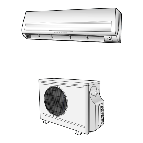
ROOM AIR CONDITIONER
INDOOR UNIT
MC26AC2-07
MC26AC2-12
Manual
1. Precautions
2. Product Specifications
3. Operating Instructions and
Installation
4. Disassembly and Reassembly
5. Troubleshooting
6. Exploded Views and Parts List
7. Block Diagrams
8. PCB Diagrams
9. Wiring Diagrams
10. Schematic Diagrams
OUTDOOR UNIT
MC26AC2X
CONTENTS
Advertisement
Table of Contents

Related Manuals for Samsung MC26AC2-07


Summary of Contents for Samsung MC26AC2-07
- Page 1 ROOM AIR CONDITIONER INDOOR UNIT OUTDOOR UNIT MC26AC2-07 MC26AC2X MC26AC2-12 Manual SERVICE AIR CONDITIONER CONTENTS 1. Precautions 2. Product Specifications 3. Operating Instructions and Installation 4. Disassembly and Reassembly 5. Troubleshooting 6. Exploded Views and Parts List 7. Block Diagrams 8.
-
Page 2: Precautions
Relocate the unit if necessary. 9. Keep children away from the unit while it is being repaired. 10. Be sure to clean the unit and its surrounding area. Fig. 1-3 No Kids Nearby! Fig. 1-4 Clean the Unit Samsung Electronics... - Page 3 MEMO Samsung Electronics...
-
Page 4: Product Specifications
2. Product Specifications 2-1 Table MC26AC2 Model INDOOR UNIT INDOOR UNIT OUTDOOR UNIT Item MC26AC2-07 MC26AC2-12 MC26AC2X Type Wall-Mounting Multi Split 2.05 x 2 Cooling BTU/h 6,995 x 2 11,942 25,932 Kcal/h 1,763x2 3,009 6,535 Perfor- Dehumidifying mance Air volume... - Page 5 2-2 Dimensions 2-2-1 Indoor Unit (Unit : mm) (Front view) Air out (Remote control) Installation plate Samsung Electronics...
- Page 6 Product Specifications 2-2-2 Outdoor Unit (Unit : mm) (Front view) (Rear view) 1000 Samsung Electronics...
-
Page 7: Pressure Graph
2-3 Pressure Graph MC26AC2-07 30.6/22.5 27/19 21.5/14.6 Outdoor drybulb temperature [deg C] MC26AC2-12 30.6/22.5 27/19 21.5/14.6 Outdoor drybulb temperature [deg C] Samsung Electronics... -
Page 8: Operating Instructions And
To select the 5 way function with the remote control, press the 5 way button one or more times until the desired mode is selected. Each time you press the 5 way button. Each 5 way indicator on the indoor unit comes on in order. Samsung Electronics... - Page 9 30 minutes, turbo operation mode is canceled and returned to the previous mode. *But, if you pressed the TURBO button in DRY or FAN mode that is changed with AUTO mode automatically. Samsung Electronics...
- Page 10 *OFF TIMER : Both timer and operation LED lights on. 11. BUZZER SOUND : Whenever the ON/OFF button is pressed or whenever change occurs to the condition which is set up or select, the compulsory operation mode, buzzer is sounded "beep". Samsung Electronics...
-
Page 11: Installation
It is harmful to the air conditioner if it is used in the following environments: greasy areas (including areas near machines), salty areas such as coast areas, areas where sulfuric gas is present such as hot spring areas. Contact your dealer for advice. Samsung Electronics... -
Page 12: Installation Diagram Of Indoor Unit And Outdoor Unit
125mm or more 125mm or more Cut the piping hole sloped slightly Remote control Outdoor unit check point A-UNIT B-UNIT Piping (Liquid) 1/4" Clamper tube Piping (Gas) 3/8" Installation plate Installation tube Pipe-connection Vinyl tape Screw Putty Drain hose Samsung Electronics... - Page 13 Result : All inert gas escapes from the indoor unit. • To prevent dirt or foreign objects from getting into the pipes during installation, do NOT remove the caps completely until you are ready to connect the piping. Samsung Electronics...
-
Page 14: Connecting The Assembly Cable
4. Pass the drain hose through the hole in the wall, making sure that it is sloping downwards, as shown in the illustrations above. The hose will be fixed permanently into position once Shield the whole installation has been tested for gas leaks; Drain hose Extension drain hose Samsung Electronics... -
Page 15: Outdoor Unit Installation
4 Replace the terminal board cover, carefully tightening the screw. 5 Connect the power cable to the auxiliary circuit breaker. Outdoor unit Indoor Unit Outdoor Unit MC26AC2-12 MC26AC2X Terminal Block MC26AC2-07 Earth terminal Circuit Breaker (Main Power cable) Earth Earth Earth... - Page 16 Terminal used exclusively for grounding Grounding resistance: less than 100 ohms (existing grounding electrode) Grounding screw hole 2. Use of a grounding electrode. • Specifications of grounding electrode. Carbon plastic Steel core PVC-insulated wire(2mm x3.5m), green Terminal, M4 Samsung Electronics...
- Page 17 And mount the service port cap to 3-way valve. (gas) Stem cap 7. Check for gas leakage. - At this time, especially check for gas leakage from the 3-way valve’s stem nuts, and from the service port cap. 3-10 Samsung Electronics...
-
Page 18: Refrigerant Refill
7. Stop operation of the air conditioner. 8. Close the 3-way valve, disconnect the pressure gauge, and open the 3-way valve again. 9. Close the cap of each valve. Samsung Electronics 3-11... -
Page 19: Refrigerant Adjustment
5~10m R410A(Add as liquid state) for every 1m. state) for every 1m. 3-2-2(i) Flare nut fixing torque Torque (kg-cm) Outer diameter Fixing Torque Final Torque ø 6.35 (Liquid Side) ø 9.52 (Gas Side) ø 12.7 (Gas Side) 3-12 Samsung Electronics... -
Page 20: "Pump Down" Procedure
At this time, cover the pipe of the indoor 8. Remove the mounting plate for the indoor unit and the other pipe using a cap or vinyl unit and move it to a new location. plug to avoid foreign material entering. Samsung Electronics 3-13... - Page 21 MEMO 3-14 Samsung Electronics...
-
Page 22: Disassembly And Reassembly
7) Pull the upper left and right of discharge softly for the outside cover to be pulled out. 8) Pull softly the lower part of discharge and push it up. Caution; Assemble the front panel and fix the hooks of left and right. Samsung Electronics... - Page 23 2) Loosen the fixing two screws and separate the motor holder. 3) Loosen the fixing screw of fan motor. (By use of M3 wrench) 4) Separate the fan motor from the fan. 5) Separate the fan from the left holder bearing. Samsung Electronics...
-
Page 24: Outdoor Unit
Fan Motor 1) Do Procedure “1” above. & Propeller Fan 2) Remove the nut flange. (Turn to the right to remove as it is a left turned screw) 3) Disassemble the propeller fan. Samsung Electronics... - Page 25 MEMO Samsung Electronics...
-
Page 26: Troubleshooting
Indoor unit heat exchanger temperature sensor Error (open or short) BIO LED blinking (1Hz) Indoor fan malfunctioning (for speed is Below 450rpm) STD, BIO and TIMER LED blinking(1HZ) EEPROM Error All LED blinking(1HZ) Option Error (option wasn’t setup or option data error) Samsung Electronics... -
Page 27: Fault Diagnosis By Symptom
Check PCB pattern. Replace ICO2 Replace main PCB. 10ms Is voltage output terminal of PC814(PC02) normal? Are voltage at #11 and #12 of the micom normal? Replace resonator (X301) 250ns Replace PC814(pc02) Is operation normal? Replace micom Samsung Electronics... - Page 28 Is the voltage at both ends of the C102 Replace the C102 electrolytic condenser in the range of DC16~DC25V? and C104. Is the voltage at both ends of the C104 electrolytic condenser DC12V? Is the IC01(KA7812) normal? Replace the IC01 Samsung Electronics...
- Page 29 Test rod location Normal voltage PCB CN72 Condition Fan operate about AC 180V pin #3 and #5 MF-C is out of order Replace MFC Fan motor Fan motor should be replaced. is out of order. Samsung Electronics...
- Page 30 “A”Compreessor or outdoor fan-motor replaced ! NO @ NO Is the room sensor normal register? 10°C 20°C 30°C 17.96kΩ 12.09kΩ 8.3kΩ YES # B Room or C Room operating Proceed to the checking points for the outdoor unit. Samsung Electronics...
- Page 31 Are the Q902, Q903 and Q905 in "Turn-on" condition? Does the operation of the Q701 lead to Check and replace the Q701 and relay. activation of the compressor relay (RY71)? (Resistance at both ends of the relay: About 150) Replace the "B" compressor. Samsung Electronics...
-
Page 32: When The Outdoor Unit Does Not Operate. (Initial Diagnosis)
Power relay should be Is rating voltage ±10% range applied relay between Terminal block out of order replaced. NO(N1) and No ! Outdoor unit is out of order. Is the room sensor normal register? 10°C 20°C 30°C 17.96kΩ 12.09kΩ 8.3kΩ Samsung Electronics... - Page 33 After training on, the Cooling operation should Normal start in five minutes. Is the number #33 of Micom (IC04) DC 5.0 V? Abnormal Micom Abnormal IC06 Is the number checking #10 of IC06 (ULN2003AFW) LOW? RY01 or Cable Check. PCB should be replaced. Samsung Electronics...
-
Page 34: Samsung Electronics
Voltage at PIN #30 of Remocon Micom change? Voltage at collecter of Q601 or Q602 change? Q601(C4375Y) or Q602(C1623Y) is faulty. IR LED(CL-1L5EU) is faulty. Voltage at pin #26 of micom (IC04) change (INDOOR UNIT)? Receiver module is faulty. Micom (IC04) is faulty. Samsung Electronics... - Page 35 IC04 DC7V? resistance (R922, R924). Does the operation of the Q702 lead to Check and replace the Q702 and relay. activation of the SV-BY relay (RY72)? (Resistance at both ends of the relay: 400Ω ) Replace the SV-BY 5-10 Samsung Electronics...
- Page 36 Does the turning on and then Check and replace the Q702 and relay. turning off of the Q702 lead to (Resistance at both ends of the relay: 400Ω) turning off of the SV-BY relay (RY72)? Replace the SV-BY solenoid. Samsung Electronics 5-11...
- Page 37 Q908 under "turn off" condition? Check and replace the D905, D909, and Q703 relay Is the Q703 turned. on, indicating the (Coil resistance at both ends of the relay:about 400Ω) operating of the SV-B relay (RY73)? Replace the SV-B solenoid valve 5-12 Samsung Electronics...
- Page 38 Is the Q704 turned on, indicating the operating condition Check and replace the D906, D910, and Q704 relay of the SV-C relay (RY74)? (Coil resistance at both ends of the relay : about 400Ω) Replace the SV-C solenoid valve Samsung Electronics 5-13...
- Page 39 • Check and replace the Q703, and Q704. turned off when the Q703 and Q704 are • Check and replace the relay when necessary. turned off. (Resistance at both ends of the relay: About 400Ω) Replace the SV-B and SV-C solenoids. 5-14 Samsung Electronics...
-
Page 40: Pcb Inspection
5-3-2 Procedure The parts should be replaced in the following procedure. Check for any faulty part. Detach the faulty part. Replace it with a new part. Check the operation of the new part. The repair is completed. Samsung Electronics 5-15... -
Page 41: Detailed Procedure
SMPS circuit is faulty 1. check voltage of IC06 IC06 is faulty (pin#10,pin#8) Set the TURBO mode : relay on 0.7[v] : relay off 12[v] 2. Voltage at terminal block RY71 is faulty ((N1) -1) rating voltage 5-16 Samsung Electronics... -
Page 42: Fault Diagnosis Of Major Parts
Red, White 130±10Ω ∞, OΩ … open or short Abnormal Measure resistance between red wire and each terminal. Stepping Motor Normal Approx. 380Ω at ambient temperature (20°C ~30°C) (UP/DOWN swing motor) ∞, OΩ … open or short Abnormal Samsung Electronics 5-17... -
Page 43: Set Up The Model Option
$ When pressing the button appear on the display, select one of them. % When pressing the button appear on the display, select one of them. ^ When pressing the button appear on the display, select one of them. 5-18 Samsung Electronics... - Page 44 If all lamps of indoor unit are flickering, Plug out and plug in again and pressing ON/OFF key to retry. If the unit is not working properly or all lamps are continuously flickering after setting the option code, see if the correct option code is set up for it’s model. Samsung Electronics 5-19...
- Page 45 Troubleshooting <Table of the option code> MODEL OPTION CODE MC26AC2-07 020000-1000D9 MC26AC2-12 020000-100340 5-20 Samsung Electronics...
- Page 46 MEMO Samsung Electronics 5-21...
-
Page 47: Exploded Views And Parts List
6. Exploded Views and Parts List 6-1 Indoor Unit 20-6 20-6-1 20-1 20-4 20-5 20-3 20-2 13-2 13-3 13-4 13-1 You can search for the updated part code number through the ITSELF. URL : http://itself.sec.samsung.co.kr Samsung Electronics... - Page 48 Exploded Views and Parts List Parts List Q’TY CODE NO Description Remark MC26AC2-12 MC26AC2-07 DB64-00354A GRILLE-AIR INLET DB63-00064A GUARD-AIR FILTER DB95-00287G ASS´Y-CLEANER FILTER DB63-00067A COVERTER-TEMINAL DB92-00248A ASSY PANEL-FRONT DB67-00051A SPACER-EVAP LOW DB67-00032A SPACER-EVAP UP DB63-00083A COVER U-BEND DB94-00040F ASSY-CROSS FAN...
- Page 49 6-2 Outdoor Unit 19(19-1~19-7) 13(13-1~13-6) 16(16-1) 9(9-1~9-2) 17(17-1~17-4) Samsung Electronics...
- Page 50 ASSY CONTROL OUT ASS'Y 19-1 2301-001379 C-OIL 4uF,450V 19-2 2501-001237 C-OIL 35uF,450V 19-3 DB26-10063C TRANS POWER DC17,AC230,400mA 19-4 DB61-00585A CASE PCB 19-5 DB61-00584B CASE CONTROL OUT SGCC-M,T0.8 19-6 DB65-40072C TERMINAL BLOCK ASS'Y 19-7 PE-M3000-02 ASSY PCB PARTS ASS'Y Samsung Electronics...
- Page 51 6-3 ASS’Y Remote Control : DB93-00251K Parts List Description Q’TY Remark INLAY LCD CASE TOP KEY RUBBER ASS'Y PCB REMOCON CASE LOW BATTERY COVER Samsung Electronics...
- Page 52 ASSY MAIN PCB DB93-01018A TERMINAL BLOCK ASSY DB65-00078A ASS'Y DISPLAY PCB DB93-00927A CONNECTOR WIRE PCB U/D DB39-00147A HOLDER CLAMP IN DB61-00219A SEAL CONTROL SIDE DB72-10191T SEAL H/CONTROL FRONT DB72-00127V SCREW MACHINE 6001-000929 CABLE CLAMP DB65-10074E SCREW TAPPING 6002-000234 Samsung Electronics...
- Page 53 MEMO Samsung Electronics...
-
Page 54: Refrigerating Cycle Block Diagram
7. Block Diagrams 7-1 Refrigerating Cycle Block Diagram INDOOR UNIT OUTDOOR UNIT Samsung Electronics... -
Page 55: Pcb Diagrams
8. PCB Diagrams 8-1 ASS’Y MAIN PCB : DB93-01018A TOP PATTERN Samsung Electronics... - Page 56 R402 R-CHIP MCR10EZHJ472 R108, R603, R901 R-CHIP MCR10EZHJ102 R201, R207, R208, R301, R401, R403, R408, R601, R607, R608 R-CHIP MCR10EZHJ561 R606 R-CHIP MCR10EZHJ471 R105, R604, R605 R-CHIP MCR10EZHJ331 R405, R407 R-CHIP MCR10EZHJ221 R106, R107 RELAY-MINIATURE F3AA012E RY72, RY73 Samsung Electronics...
- Page 57 PCB Diagrams BOTTOM PATTERN Samsung Electronics...
- Page 58 8-2 PCB OUTDOOR UNIT : PE-M3000-02 Samsung Electronics...
- Page 59 RY72~74, 77, 78 RELAY JQ1A-12V IC01 HEAT-SINK 25MM IC01 SCREW-TAPPING PH 3 L6 AB FEFZY IC01 IV-VOLT REGU KA7812 IC02 IC-VOLT REGU KA7805 F701 FUSE AC250V 3.15A 20MM F701 FUSE-HOLDER FH51H 7.5A TB71 TERMINAL TAP YTR-250 OPJ2 JUMP-WIRE PI0.6SM T52MM Samsung Electronics...
- Page 60 MODULE REMOCON RM01 KSM-713TH5 TACT SWITCH SW01 KPT-1105A C-CERAMIC 102K C-CERAMIC 104Z DIODE SWITCHING IN4148 R-CARBON R01, R02, R03 470 1/2W 5% JUMP 10mm CONNECTOR WAFER CN02 SMAW200-05 CONNECTOR WIRE CN01 UL1007, AWG#26 8-4 ASS’Y CENTER DISPLAY : DB93-00859A Samsung Electronics...
- Page 61 MEMO Samsung Electronics...
-
Page 62: Wiring Diagrams
9. Wiring Diagrams 9-1 Indoor Unit Samsung Electronics... - Page 63 9-2 Outdoor Unit Samsung Electronics...
-
Page 64: Schematic Diagrams
10. Schematic Diagrams 10-1 Indoor Unit Samsung Electronics 10-1... - Page 65 Itself Solution Integrated technology supporting electronic library http://itself.sec.samsung.co.kr Copyright © 2002 By Samsung Electronics Co., Ltd. All rights reserved. This manual may not, in whole or in part, be copied, photocopied, reproduced, translated, or converted to any electronic or machine readable from without prior written permission of Samsung Electronics Co., Ltd.
- Page 66 ELECTRONICS © Samsung Electronics Co., Ltd. Mar. 2003. Printed in Korea. Code No. DB98-11868A(1)
Need help?
Do you have a question about the MC26AC2-07 and is the answer not in the manual?
Questions and answers