
Related Manuals for Samsung MCU-S6NEK3N


Summary of Contents for Samsung MCU-S6NEK3N
-
Page 1: Air Conditioner
Air conditioner Installation manual MCU-S6NEK3N • Thank you for purchasing this Samsung air conditioner. • Before operating this unit, please read this user manual carefully and retain it for future reference. -
Page 2: Table Of Contents
Contents Safety Information Safety Information Mesures de sécurité Preparation Preparing the installation Accessories Selecting the refrigerant pipe for installation HR Changer, MCU, Indoor and outdoor unit compatible table Installation Space requirements Installing the unit Method and cautions on brazing the pipe Method and cautions on refrigerant pipe insulation Refrigerant piping works Installing the circuit breaker and wires... -
Page 3: Safety Information
Safety Information The safety information and precautions below must be kept for the safety of users and installers. Before installing an air conditioner, please read this manual thoroughly to ensure that you know how to • Safety precautions must be taken when installing the refrigerant pipe. the regulations. - Page 4 Safety Information leaking spot so that causes serious injuries. When the electric wire is damaged, you must exchange it by the manufacturer or its service agent, or a person When turning on the power, make sure to connect the power supply to the circuit breaker designated for indoor units.
- Page 5 FOR INSTALLATION CAUTION Make sure to earth. Make sure that the condensed water from the drain hose runs out properly based on this installation manual and insulate the drain pipe so that frost does not generate. Install the power cable and communication cable of MCU at least 1m away from the electric appliances and at least 2m away from the lightning rod.
-
Page 6: Mesures De Sécurité
Mesures de sécurité • • AVERTISSEMENT MISE EN GARDE MONTAGE AVERTISSEMENT L'installation doit être faite par l'installateur ou son agent de service. incendie et ainsi de suite. Installez l'appareil conformément au manuel d'installation. Lors de l'installation de l'appareil dans un espace restreint, prenez les mesures appropriées pour éviter que la l'installation. - Page 7 Installez l'appareil en toute sécurité à un emplacement qui peut supporter son poids. blessures. l'appareil. Lorsque vous mettez l'appareil sous tension, veillez à effectuer le raccordement à un disjoncteur conçu pour les unités intérieures. (ELCB, ELB, MCCB) MONTAGE AVERTISSEMENT provoquer une traction sur le bornier. Veillez à...
- Page 8 Mesures de sécurité MONTAGE MISE EN GARDE Veillez à effectuer une mise à la terre conforme. Veillez à ce que les condensats s'évacuent correctement par le tuyau de vidange conformément aux givre. Installez la MCU loin de tout dispositif d'éclairage utilisant un ballast. N'installez pas l'appareil dans les lieux suivants.
-
Page 9: Preparation
Preparing the installation Accessories Insulation Insulation Installation Pattern Name Cable tie Tube Cap (for pipe) (for base) manual sheet Shape Y-connector Name [ Ø 9.52 mm (3/8"): DB96-23143A ], [ Ø 15.88 mm (5/8"): DB96-23144A ] Shape Selecting the refrigerant pipe for installation below in selecting the installation pipe. -
Page 10: Hr Changer, Mcu, Indoor And Outdoor Unit Compatible Table
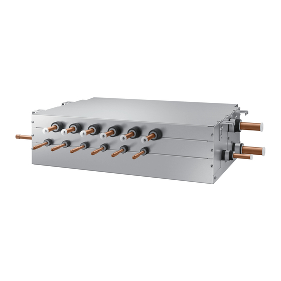
Preparing the installation HR Changer, MCU, Indoor and outdoor unit compatible table DVM S Eco HR Outdoor Unit HR Changer Sub MCU Indoor Unit AM****XMD*R AM****N**** • • • • English... - Page 11 DVM S HR / DVM S WATER HR Outdoor Unit Indoor Unit AM****XV**R AM****N**** AM****XW**R Model Description own installation manual. Gas pipe connected to the indoor unit <Side view of MCU> < MCU (MCU-S6NEK3N) > English...
-
Page 12: Space Requirements
Space requirements <Spaces with developed ceiling> Bulkhead Hallway Hallway <There is no risk of noise transfer> <There is a risk of noise transfer> Minimize the size of the hole between the walls and the pipe connection. After the installation, block the gap 12 English... - Page 13 Ceiling concrete or more Refrigerant pipe or more English...
-
Page 14: Installing The Unit
Installing the unit Unit MCU-S4NEK3N Model name The number of branches Not included Cannot connect indoor unit without HR Changer HR Changer HR Changer < Serial installation for DVM S ECO > < Parallel installation for DVM S ECO > 14 English... - Page 15 MCU address switch switch 2 3 4 A B C D 2 3 4 2 3 4 2 3 4 2 3 4 Combination Default Combination Combination of install the indoor unit. • Since the diagram is made of paper, it may shrink or stretch before drilling the holes maintain the correct dimensions between the markings.
- Page 16 Installing the unit The upper and the lower side of MCU is distinguished, so be careful not to turn the unit upside down when rubber Washer <Fixing the bolt> welding Default installing direction. When connecting the MCU with outdoor units, default direction is set in the MCU. English...
-
Page 17: Method And Cautions On Brazing The Pipe
<Good Example of connection> <No Good Example of connection> Method and cautions on brazing the pipe Keeping refrigerant pipe clean and dry clean, dry and sealed during installation. Exposure place Exposure time Sealing type Shorter than one month Taping Taping Brazing the pipe Make sure that there is no moisture inside the pipe. -
Page 18: Method And Cautions On Refrigerant Pipe Insulation
Installing the unit Method and cautions on refrigerant pipe insulation hoses and pipes when there is no sign of leakage. No gap Butadien Rubber separately around each refrigerant pipe. • Always make the seam of pipes face upwards. Insulation pipe the insulation too much. -
Page 19: Refrigerant Piping Works
Refrigerant piping works Insulation Insulation should not be pressed. insulator. Gas pipe space. thicker insulation. Gas pipe • • Wind the refrigerant pipe with insulation tape Hanger • Install the refrigerant pipe respecting that the insulation does not get thinner on the bent part or hanger of pipe. -
Page 20: Installing The Circuit Breaker And Wires
Refrigerant piping works Installing the circuit breaker and wires Power supply MCCB Power cable Earth cable Communication cable Installing the wire Indoor Indoor Indoor Indoor Indoor MCCB Unit MCCB Unit Unit Unit Unit Unit Unit Indoor Unit Indoor Indoor Indoor MCCB Unit Unit... - Page 21 Hole for MCU main power supply Hole for communication Nominal dimensions for cable [mm² (inch²)] Nominal dimensions for screw [mm (inch)] Standard dimension [mm (inch)] Allowance [mm (inch)] Standard dimension [mm (inch)] Allowance [mm (inch)] Standard dimension [mm (inch)] Allowance [mm (inch)] Min.
-
Page 22: Wiring Works
Wiring works Setting MCU address and port Process MCU address Set MCU address by rotary switch. setting MCU Address MCU Address Default Setting MCU setting for using each port 2 3 4 Default 2 3 4 setting for using 2 3 4 2 3 4 Default Combination... - Page 23 MCU address and port setting Manual setting : for indoor unit Setting Main The unit digit of Mode address unit address unit an indoor unit Remote Controller Display IndicationDetails Indication Details Indication Details Indication Details Indication Details Indication Details No Main address Indication Address...
- Page 24 Wiring works and port setting for indoor unit Data bit Main Main menu menu Description Menu menu default MAIN address None the address MAIN address None the product option Refer to the the installation None installation manual of the option setting connected the installation None...
- Page 25 • pipe. This indoor unit only operate to cooling mode. HR Changer • • le changeur HR. English...
- Page 26 Wiring works Check whether power is supplied or not. power supply in the indoor unit. option. • • • • Option No. : 05XXXX-1XXXXX-2XXXXX-3XXXXX (When setting (When setting (When setting Use of Auto Change Standard Standard heating Standard cooling for mode change setting Remote Controller...
- Page 27 Standard for mode diffference between indoor units changing Cooling mode change Heating mode Remote Controller Display Indication Details Indication Details Indication Details Indication Details is more than Indication and Details Display MCU status address Display segment Display Contents Remarks (Pushed time) Blank Blank MCU address...
- Page 28 Wiring works Display segment Display Contents Remarks (Pushed time) • Blank Version Display segment Display Contents Remarks (Pushed time) Indoor unit main address for matching with port A A Indoor unit main address for matching with port B Indoor unit main address for matching with port C 6 Indoor unit main address of port C : 6 Indoor unit main address for matching with port D K4 Switch (Electronic Valve Manual Control)
-
Page 29: Appendix
Commisioning complete it. Item Check not to install the MCU frame. English... - Page 30 Memo 30 English...
- Page 31 English...
Need help?
Do you have a question about the MCU-S6NEK3N and is the answer not in the manual?
Questions and answers