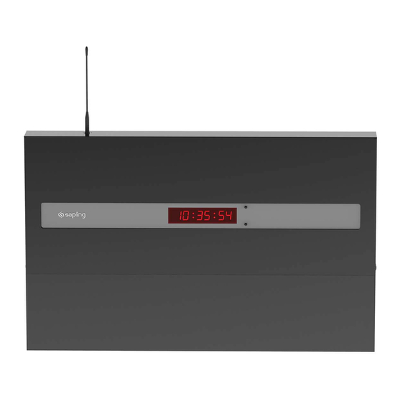
Sapling SMA 2000 Series Installation Manual
Master clock
Hide thumbs
Also See for SMA 2000 Series:
- Installation manual (65 pages) ,
- Installation manual (40 pages)
Table of Contents
Advertisement
Quick Links
Download this manual
See also:
Installation Manual
Advertisement
Table of Contents

Related Manuals for Sapling SMA 2000 Series


Summary of Contents for Sapling SMA 2000 Series
- Page 1 Installation Manual V3 SMA 2000 Series Master Clock The Sapling Company, Inc. 215.322.6063 P. 1633 Republic Road 215.322.8498 F. Huntingdon Valley, PA 19006 www.sapling-inc.com...
-
Page 2: Table Of Contents
The Sapling Company, Inc. 215.322.6063 P. 1633 Republic Road 215.322.8498 F. Huntingdon Valley, PA 19006 www.sapling-inc.com SMA 2000 Master Clock Table of Contents Installation Instructions Accessing the Web Interface when Using a Static IP 23 Wall Mount 3 Accessing the Web Interface when Using a Crossover Cable 23... -
Page 3: Wall Mount
The Sapling Company, Inc. 215.322.6063 P. 1633 Republic Road 215.322.8498 F. Huntingdon Valley, PA 19006 www.sapling-inc.com Wall Mount Installation Fig 1 1. Remove the cover of the wiring panel (Fig 1). 2. Mark the four drilling points on the wall based on the drawing above. -
Page 4: Rack Mount
The Sapling Company, Inc. 215.322.6063 P. 1633 Republic Road 215.322.8498 F. Huntingdon Valley, PA 19006 www.sapling-inc.com Rack Mount Installation 1. The master clock is 1U in size. Install the threaded nuts in the desired location in the rack rails. 2. Put the nylon washers on the two screws supplied. -
Page 5: Before You Get Started
The Sapling Company, Inc. 215.322.6063 P. 1633 Republic Road 215.322.8498 F. Huntingdon Valley, PA 19006 www.sapling-inc.com Before You Get Started Installing the Master Clock with the Line Cord Receptacle Remainder of cord not shown Caution! Do not plug in the power cord until the following steps are completed. -
Page 6: Rear View Of Unit
RS485 Input/Output This terminal block is where connections would be landed for RS485 communication to and from other Sapling systems. Inputs This terminal block is where connections would be landed to use the SMA as a slave clock when being controlled by another system. -
Page 7: Remote Antenna Mounting Instructions (Rack Mount Only)
The Sapling Company, Inc. 215.322.6063 P. 1633 Republic Road 215.322.8498 F. Huntingdon Valley, PA 19006 www.sapling-inc.com Remote Antenna Mounting Instructions 1. Remove the cover of the wiring panel. 2. Mark the four drilling points on the wall based on the drawing above. - Page 8 The Sapling Company, Inc. 215.322.6063 P. 1633 Republic Road 215.322.8498 F. Huntingdon Valley, PA 19006 www.sapling-inc.com System Connections – Wired Systems 2 Wire Digital Communication...
-
Page 9: Wired Systems - Rs485 Communication
The Sapling Company, Inc. 215.322.6063 P. 1633 Republic Road 215.322.8498 F. Huntingdon Valley, PA 19006 www.sapling-inc.com System Connections – Wired Systems RS485 Communication... -
Page 10: Wired Systems - Sync-Wire Communication
The Sapling Company, Inc. 215.322.6063 P. 1633 Republic Road 215.322.8498 F. Huntingdon Valley, PA 19006 www.sapling-inc.com System Connections – Wired Systems Sync-Wire Communication... -
Page 11: Minute Correction
The Sapling Company, Inc. 215.322.6063 P. 1633 Republic Road 215.322.8498 F. Huntingdon Valley, PA 19006 www.sapling-inc.com Inputs – Sync-Wire Inputs Installation 59 Minute Correction Dry Contact Closure 110VAC Interface 24VAC Interface N.O. 58 Minute Corrections 1–4 Dry Contact Closure 110VAC Interface 24VAC Interface N.O. - Page 12 The Sapling Company, Inc. 215.322.6063 P. 1633 Republic Road 215.322.8498 F. Huntingdon Valley, PA 19006 www.sapling-inc.com Inputs – Sync-Wire Inputs Installation National Time/Rauland Dry Contact Closure 110VAC Interface 24VAC Interface Rauland Digital Output Input...
-
Page 13: Dukane Digital
The Sapling Company, Inc. 215.322.6063 P. 1633 Republic Road 215.322.8498 F. Huntingdon Valley, PA 19006 www.sapling-inc.com Inputs – Sync-Wire Inputs Installation Dukane Digital Once a Day Pulse Dry Contact Closure... -
Page 14: Fire Alarm Input
Fire Alarm Interface Installation The Fire Alarm Interface allows a relay closure to be connected to the SMA master clock that allows the user to interface the existing fire alarm with the Sapling SBD 1000 or SBD 2000 series digital clocks. N.O. -
Page 15: Setting The Time From The Led Display
The Sapling Company, Inc. 215.322.6063 P. 1633 Republic Road 215.322.8498 F. Huntingdon Valley, PA 19006 www.sapling-inc.com User Level Programming Setting the Time from the LED Display To set the time, press the top button to change the hour and/or the bottom button the set the minute. -
Page 16: Setting The Rs485 Data Rate
The Sapling Company, Inc. 215.322.6063 P. 1633 Republic Road 215.322.8498 F. Huntingdon Valley, PA 19006 www.sapling-inc.com User Level Programming Option 3 - Set Day: Use the bottom button to scroll between “01-31”. Option 10 - Technical Mode: If technical mode is desired, press the bottom button until “08” is reached. -
Page 17: Setting Clock #1 & #2 Sync-Wire Outputs
The Sapling Company, Inc. 215.322.6063 P. 1633 Republic Road 215.322.8498 F. Huntingdon Valley, PA 19006 www.sapling-inc.com User Level Programming Option 20 - Programming the Clock #1 Circuit: Press the bottom button to scroll through “1”, “2”, “3”, “4”, “5”, “6”, “7”, “8” & “9”. Please refer to relay selection mode on page 21. - Page 18 The Sapling Company, Inc. 215.322.6063 P. 1633 Republic Road 215.322.8498 F. Huntingdon Valley, PA 19006 www.sapling-inc.com User Level Programming Option 25 - Programming the Clock #2 Circuit: Press the bottom button to scroll through “1”, “2”, “3”, “4”, “5”, “6”, “7”, “8” & “9”. Please refer to relay selection mode on page 21.
-
Page 19: Setting The Primary And Secondary Inputs
The Sapling Company, Inc. 215.322.6063 P. 1633 Republic Road 215.322.8498 F. Huntingdon Valley, PA 19006 www.sapling-inc.com User Level Programming Option 30 - Set the Primary Input: Press the bottom button to scroll between “1-13” to select the input. 00 - Real Time Clock... -
Page 20: Viewing The Last Time The Clock Received An Input Signal
The Sapling Company, Inc. 215.322.6063 P. 1633 Republic Road 215.322.8498 F. Huntingdon Valley, PA 19006 www.sapling-inc.com User Level Programming Option 35 - Once a Day Pulse Input - Set Minutes This option is only available when option 30 or 31 is set to 11. Press the bottom button to scroll through “00-59”. -
Page 21: Setting Diagnostics
The Sapling Company, Inc. 215.322.6063 P. 1633 Republic Road 215.322.8498 F. Huntingdon Valley, PA 19006 www.sapling-inc.com User Level Programming Option 50 - Entering Diagnostic Mode Press the bottom button to scroll between “E - d”. Setting the option to “E” will enable the option and will enter diagnostic mode. Setting the option to “d”... - Page 22 The Sapling Company, Inc. 215.322.6063 P. 1633 Republic Road 215.322.8498 F. Huntingdon Valley, PA 19006 www.sapling-inc.com System Connections – Wired Systems Sync-Wire Communication – Protocol Definitions 58th minute (1) The hourly correction for 55 seconds every hour from XX:58:05 to XX:59:00. The daily correction (5 a.m. & 5 p.m.) is ten correction cycles sent to the relay (each for 95 seconds) beginning at 5:05:00, 5:07:00, 5:09:00, 5:11:00, 5:13:00, 5:15:00, 5:17:00, 5:19:00, 5:21:00, and 5:23:00.
-
Page 23: Accessing The Web Interface When Using A Static Ip
The Sapling Company, Inc. 215.322.6063 P. 1633 Republic Road 215.322.8498 F. Huntingdon Valley, PA 19006 www.sapling-inc.com Web Interface Programming The web interface is an optional feature and is not available on all units. Please make sure that ports 123 and 80 are open on the firewall. -
Page 24: Log In
The Sapling Company, Inc. 215.322.6063 P. 1633 Republic Road 215.322.8498 F. Huntingdon Valley, PA 19006 www.sapling-inc.com Web Browser Programming Log In Password There are two levels of passwords that will enable the user to access features. The first level is the user level programming that includes features like setting the time, date, adding and editing events and schedule changes. -
Page 25: Main Menu
The Sapling Company, Inc. 215.322.6063 P. 1633 Republic Road 215.322.8498 F. Huntingdon Valley, PA 19006 www.sapling-inc.com Web Browser Programming Main Menu Technician Menu This link will access the Technician Menu log-in page. The Technician Menu is password protected and has access to system settings, IP settings, as well as feature settings for the master clock. -
Page 26: Technician Level Menu
The Sapling Company, Inc. 215.322.6063 P. 1633 Republic Road 215.322.8498 F. Huntingdon Valley, PA 19006 www.sapling-inc.com Web Browser Programming Technician Level Menu System Settings This link, when clicked, will enter the System Settings pages. These pages include the user password, the RS485 data rate, setting the offset, the input selection, setting Clock #1 and Clock #2 sync-wire protocol outputs and resetting the unit back to manufacturer’s default settings. - Page 27 The Sapling Company, Inc. 215.322.6063 P. 1633 Republic Road 215.322.8498 F. Huntingdon Valley, PA 19006 www.sapling-inc.com Web Browser Programming System Settings Page 1 User Password This field allows the user to enter a new password for the user level programming. The default is 1111.
- Page 28 The Sapling Company, Inc. 215.322.6063 P. 1633 Republic Road 215.322.8498 F. Huntingdon Valley, PA 19006 www.sapling-inc.com Web Browser Programming System Settings Page 2 Input Selection This drop-down list allows the user to select which input will control the master clock. The choices are: •...
-
Page 29: Ip Settings
The Sapling Company, Inc. 215.322.6063 P. 1633 Republic Road 215.322.8498 F. Huntingdon Valley, PA 19006 www.sapling-inc.com Web Browser Programming IP Settings Page 1 Gateway IP Address This field allows the user to set the Gateway IP address for the master clock. - Page 30 The Sapling Company, Inc. 215.322.6063 P. 1633 Republic Road 215.322.8498 F. Huntingdon Valley, PA 19006 www.sapling-inc.com Web Browser Programming IP Settings Page 2 Retry Failed-Server After This field allows the user to specify how many times it will attempt to access the time from a server before it moves on to the next one.
- Page 31 The Sapling Company, Inc. 215.322.6063 P. 1633 Republic Road 215.322.8498 F. Huntingdon Valley, PA 19006 www.sapling-inc.com Web Browser Programming IP Settings Page 3 MAC Address This displays the MAC address for the master clock. IP Address This display the IP address for the master clock.
-
Page 32: Clock Features
The Sapling Company, Inc. 215.322.6063 P. 1633 Republic Road 215.322.8498 F. Huntingdon Valley, PA 19006 www.sapling-inc.com Web Browser Programming Clock Features Display Format This drop-down list allows the user to select whether they want 12 hour or 24 hour mode to be displayed on the LCD and LED. -
Page 33: Database Maintenance
The Sapling Company, Inc. 215.322.6063 P. 1633 Republic Road 215.322.8498 F. Huntingdon Valley, PA 19006 www.sapling-inc.com Web Browser Programming Database Maintenance Upload Database This button, when pressed, will upload the current schedules and events, and place it in a file for backup purposes. -
Page 34: Support
What is the maximum length I can go with the GPS cable? When the GPS option is purchased, a 75 foot cable comes standard with the unit. This is Sapling’s recommended longest distance. Is there a Converter option like there was in the SSM and the GPS? No, the Converter Box should be purchased separately from the unit when using a two wire digital communication system. -
Page 35: Troubleshooting
The Sapling Company, Inc. 215.322.6063 P. 1633 Republic Road 215.322.8498 F. Huntingdon Valley, PA 19006 www.sapling-inc.com Support Troubleshooting The master clock will not power up. What do I do? Make sure the power cord is securely connected to the power outlet and to the back of the SMA master clock. Upon being connected to power, the master clock should boot up instantly.
Need help?
Do you have a question about the SMA 2000 Series and is the answer not in the manual?
Questions and answers