
Related Manuals for Thermolec B-5U-FFB


Summary of Contents for Thermolec B-5U-FFB
-
Page 1: Installation Instructions
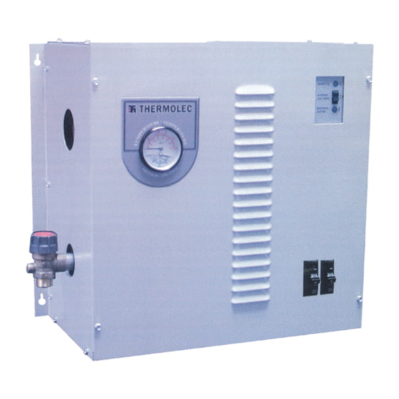
THERMOLEC Installation Instructions Electric Boilers (USA) DECEMBER 2010 VERSION 11... - Page 3 Components Incoloy elements Manual reset Solid state relays thermal cut-out Electronic temperature sensor Magnetic back-up contactor Mounting holes Outlet 1-1/4ÊÊ NPT Boiler control transformer Temperature / pressure 18” gauge Circuit breaker Pump relay Inlet 1-1/4ÊÊ NPT 9” Ground lug 18” Fuse and Pump relay terminals fuse holder...
- Page 4 Standard specifications for all models Table 2 Standard Models Specifications @ 240V / 1ph (U.S.A.) Dual-Energy Models B-5U-FFB B-6U-FFB B-8U-FFB B-9U-FFB B-10U-FFB B-12U-FFB B-15U-FFB 5.75 11.5 BTU / H 17,060 19,619 27,296 30,708 34,120 39,238 51,180 Total Amps 20.83 23.96 33.33...
- Page 5 These instructions should be used as a general guide only. Electrical Code and local utility requirements must be followed and take precedence over these instructions. Thermolec electric boilers are manufactured with quality components for maximum life, durability and minimum service. To ensure a satisfactory installation it is imperative that you read these instructions carefully before installing and operating the heating system.
- Page 6 Water circulation and plumbing notes The system is designed to operate with a maximum output temperature of 190°F or lower and a temperature rise across the unit of 20°F or lower. Please refer to Table 4 for the minimum flow rate versus the capacity of the boiler. Table 4 Minimum Water Flow Rate vs Capacity Capacity (kW)
-
Page 7: Mechanical Installation
The automatic pressure relief valve supplied with the boiler is required to prevent dangerous pressure build-ups in the system in case of system malfunction and may under certain conditions vent hot water. Do not install the system where water could damage rugs, furniture, etc. When piping the relief valve to a drain, check with local authority for recommended method of installation. - Page 8 Electronic Aquastat MAXIMUM WATER TEMPERATURE MINIMUM WATER TEMPERATURE °F Fig. 4 Fig. 5 The outdoor sensor will : Maintain the selected maximum water temperature when the outdoor temperature is at +14° F or colder. b) Automatically and proportionally compensate by varying the water temperature between the maximum and minimum when the outdoor temperature is between +14°F and +50°F.
- Page 9 Set the thermostat above the room temperature. The system should start. Make sure the pump starts running as soon as the system starts. 9.10 Heating stages will be switched ON in sequence at 30 second intervals, confirmed by green lights on the left hand side of the PC board on the TH600 or by red lights on the right hand side on the D22-B.
-
Page 10: Installation Examples
Water is always passing through both boilers even if only one heat source is selected at a time. 11.3 Installation C shows a Thermolec electric boiler in a Primary/Secondary Piping Configuration. Water is pumped through multiple zones (more than two equally sized zones). -
Page 11: Warranty
Thermolec’s responsibility shall be limited in any case to the replacement or repair, in its factory or in the field, by others chosen by Thermolec, at its option, of such boiler or parts thereof, as shall prove to be defective within the warranty period. - Page 12 Page 10...
- Page 13 Page 11...
- Page 14 ALL-ELECTRIC INSTALLATION (Illustration A) Page 15...
- Page 15 DUAL-ENERGY SERIES INSTALLATION (Illustration B) Page 17...
- Page 16 PRIMARY / SECONDARY PIPING INSTALLATION (Illustration C) Page 19...
- Page 17 PUMP WIRING WITH FOSSIL FUEL BACKUP BOILER 120 VAC OUTPUT W/ HEAT CALL 120V COIL 120 VAC CIRCULATION POWER PUMP SUPPLY ELECTRIC BOILER CIRCULATION PUMP Page 21...
- Page 20 April 9, 2010 Electric Boiler Troubleshooting Guide Call for heat and boiler doesn’t start, no lights on circuit board. Try the following: 1. Confi rm that the boiler is connected to 240/1 power, main panel breakers are ON, breakers supplying boiler in panel are ON. 2.
- Page 21 Call for heat, boiler starts and back-up contactor is noisy. Try the following: 1. Check for 24VAC out of transformer to contactor. If less than 24VAC, change transformer. If 24VAC, contactor is defective or contacts are dirty. Continue. 2. Turn OFF boiler circuit breakers. Disconnect wires to contactor, remove contactor from boiler, remove two screws from bottom metal plate on contactor, carefully remove coil and magnetic core, carefully clean surface of magnetic contacts with emery cloth.
- Page 24 Bloomington, MN 55425 Phone: (952) 854-4400 Fax (952) 854-4441 Representing the following quality manufacturers: Thermolec: Electric heating products including boilers, plenum heaters and duct heaters. (In Stock) www.thermolec.com Summeraire: Residential and Light Commercial air-to-air heat recovery ventilators and accessories (In Stock) www.summeraire.com Soler &...
Need help?
Do you have a question about the B-5U-FFB and is the answer not in the manual?
Questions and answers