Sign In
Upload
Download
Add to my manuals
Delete from my manuals
Share
URL of this page:
HTML Link:
Bookmark this page
Add
Manual will be automatically added to "My Manuals"
Print this page
×
Bookmark added
×
Added to my manuals
Manuals
Brands
Thermolec Manuals
Boiler
B-5U-FFB
Installation instructions manual
Thermolec B-5U-FFB Installation Instructions Manual
Electric
Hide thumbs
Also See for B-5U-FFB
:
Installation instructions manual
(24 pages)
1
2
3
4
5
6
7
8
9
10
11
12
13
14
15
16
17
18
19
20
21
page
of
21
Go
/
21
Bookmarks
Advertisement
Quick Links
Download this manual
See also:
Instruction and Installation Manual
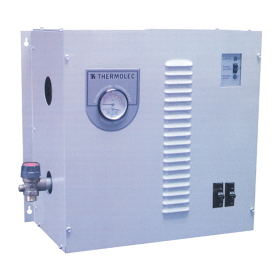
THERMOLEC
Installation
Instructions
for
Electric
Boilers (USA)
JULY 2006
VERSION 9
1
Table of
Contents
Previous
Page
Next
Page
1
2
3
4
5
Advertisement
Need help?
Do you have a question about the B-5U-FFB and is the answer not in the manual?
Ask a question
Questions and answers
Related Manuals for Thermolec B-5U-FFB
Boiler Thermolec B-5U-FFB Installation Instructions Manual
Electric boilers (24 pages)
Boiler Thermolec B-23U-FFB Installation Instructions Manual
Electric boilers (24 pages)
Boiler Thermolec B-5 Installation Instructions Manual
Thermolec model b electric boilers (21 pages)
Boiler Thermolec B-15U-M Installation Instructions Manual
Electric (21 pages)
Boiler Thermolec TB42 Installation Instructions Manual
(29 pages)
This manual is also suitable for:
B-6u-ffb
B-8u-ffb
B-9u-ffb
B-10u-ffb
B-12u-ffb
B-15u-ffb
...
Show all
B-5u-m
B-6u-m
B-8u-m
B-9u-m
B-10u-m
B-12u-m
B-15u-m
B-18u-ffb
B-24u-ffb
B-30u-ffb
B-35u-ffb
B-40u-ffb
B-18u-ml b-24u-m
B-30u-m
B-35u-m
B-40u-m
Print
Rename the bookmark
Delete bookmark?
Delete from my manuals?
Login
Sign In
OR
Sign in with Facebook
Sign in with Google
Upload manual
Upload from disk
Upload from URL


Need help?
Do you have a question about the B-5U-FFB and is the answer not in the manual?
Questions and answers