
Related Manuals for Thermolec TB42


Summary of Contents for Thermolec TB42
- Page 1 THERMOLEC FFB (STANDARD) Installation Instructions Electric Boilers (USA) FFB (LARGE) June 2018 Version 12 (TANDEM)
- Page 2 ATTENTION Under normal conditions additives or treatments for the system water is not required, however ex- treme water conditions may void the warranty. To be sure that this is not the case, when installing the boiler make sure that the source water: - does not contain a high level of chlorine - is not contaminated with excessive sediment - is close to a neutral pH of 7.0 ±1.0...
-
Page 3: Table Of Contents
Table of Contents Warning Section Instructions Licensing Servicing Operation unpacking III. Boiler Components Before you begin Water condition Clearances/location Installation/Piping Wiring Sequence of operations Troubleshooting VII. Wiring Diagrams VIII. Piping Diagrams Maintenance Warranty Page 1... -
Page 4: Warning Section
Warning Section Read all instructions before installing boiler Boilers must be wired by a licensed electrician When servicing boiler To avoid electrical shock, disconnect electrical supply before performing maintenance. To avoid severe burns, allow boiler to cool before performing maintenance. Boiler operation Do not block the top and bottom vents on boiler (could cause components to overheat). -
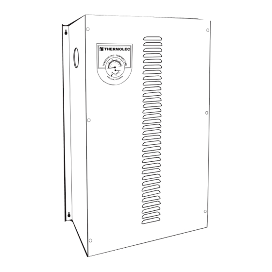
Page 5: Boiler Components
III. Boiler Components Model FFB Incoloy elements Manual reset Solid state relays thermal cut-out Electronic temperature sensor Magnetic back-up contactor Mounting holes Outlet 1-1/4ÊÊ NPT Boiler control transformer Temperature / pressure 18” gauge Circuit breaker Pump relay Inlet 1-1/4ÊÊ NPT 9”... - Page 6 Table 2 B-5U-FFB B-6U-FFB B-8U-FFB B-9U-FFB B-10U-FFB B-12U-FFB B-15U-FFB B-18U-FFB B-20U-FFB B-23U-FFB 5.75 12/11.5 BTU/H 17060 19619 27296 30708 34120 39238 51180 61416 68242 78479 Total Amps 27.76 33.3 41.64 Supplies & Breaker Size 1 x 40A 3P 1 x 50A 3P 1 x 60A 3P 1 x 60A Total Amps 20.83...
- Page 7 TANDEM BOILER CONFIGURATION DETAILS Primary Model BTU/H Voltage Total Amp. Amperage Breaker Disconnect Secondary 83.37 2 X 60A 208/3 116.67 33.3 1 X 50 3 X 60 240/1 172.92 47.92 1 X 60 141598 72.17 2 X 50 240/3 101.04 28.87 1 X 40 36.1...
-
Page 8: Before You Begin
Before You Begin Water Condition Freeze protection can be used, no greater than 50% solution. Any non-automotive Glycol can be used. Any time water hardness is greater than 9 (ph), water additives, in line fi lters or fi lling with distilled water should be used. - Page 9 Piping section a) The system is designed to operate with a maximum output temperature of 190°F or lower and a temperature rise across the unit of 20°F or lower. Please refer to Table 4 for the minimum fl ow rate versus the capacity of the boiler.
- Page 10 The installation must have a drain valve, an expansion tank and maintenance valves must be installed at the supply outlet of the unit. This “T” must be equipped with a reducing bushing 1-1/4” to 3/4” NPT, facing upwards, to accept a 3/4” NPT pressure relief valve. This safety valve must be installed vertically. Except for the pressure relief valve, the above plumbing supplies are not supplied with the unit.
-
Page 11: Wiring
Wiring Section a) Disconnect all power sources before opening the main panel and working within. b) Read the nameplate and other markings carefully and wire strictly in accordance with the wiring diagram. c) Wires and protective equipment must be sized according to the applicable Electrical Code. d) Use only wires suitable for minimum 167°F. -
Page 12: Sequence Of Operations
h) Connect the thermostat or the zone valve end switch wires to “C” and “W1” terminals on the electronic board. Power stealing thermostats require an isolation relay (not included) and should not be powered by the W1 and C terminals. i) Circulating Pump Control. - Page 13 After the call for heat is satisfi ed, the elements will be sequenced off and the pump relay will be de-energized. With a call for heat, the outdoor sensor will vary the supply water temperature based on outdoor temperature and will disable the boiler any time the outdoor temperature is above 68°F. If there is a call for heat and S1/S2 terminals are open, electric boiler will shut down.
- Page 14 Trouble shooting Section Troubleshooting Guide - FFB model Call for heat and boiler doesn’t start, no lights on circuit board. Try the following: 1. Confi rm that the boiler is connected to 240/1 power, main panel breakers are ON, breakers supplying boiler in panel are ON.
- Page 15 Call for heat, boiler starts and back-up contactor is noisy. Try the following: 1. Check for 24VAC out of transformer to contactor. If less than 24VAC, change transformer. If 24VAC, contactor is defective or contacts are dirty. Continue. 2. Turn OFF boiler circuit breakers. Disconnect wires to contactor, remove contactor from boiler, remove two screws from bottom metal plate on contactor, carefully remove coil and magnetic core, carefully clean surface of magnetic contacts with emery cloth.
- Page 16 Troubleshooting Guide - TMB model Boiler will not start, no lights on the board Confi rm 24vac to the board. If no, check main power at breakers, from the transformer, and through the fuse. If Yes, Confi rm heat call at control board by installing a jumper at W1 and C. If the boiler starts, check thermostat.
- Page 17 B18-B20...
- Page 18 B9-B11 TMB...
- Page 19 TANDEM BOILER 480V 3 PH...
- Page 20 Page 18...
- Page 21 SUPPLY CIRCULATING PUMP ROOM THERMOSTAT MAINTENANCE VALVE MAINTENANCE BLEEDING VALVE VALVE AUTOMATIC AIR VENT TEMPERATURE / OUTDOOR RESET SAFETY VALVE PRESSURE GAUGE SENSOR LOAD MANAGEMENT CONTROL PURGER SHUT-OFF VALVE POWER SUPPLY 120V / 1Ø WATER FEED PRIMARY PUMP POWER DRAIN SUPPLY BOILER CONNECTION...
- Page 22 SUPPLY CIRCULATING PUMP ROOM THERMOSTAT MAINTENANCE VALVE MAINTENANCE BLEEDING VALVE May be replaced with tandem VALVE configuration - see illustration AA AUTOMATIC AIR VENT TEMPERATURE / OUTDOOR RESET SAFETY VALVE PRESSURE GAUGE SENSOR LOAD MANAGEMENT CONTROL PURGER SHUT-OFF VALVE POWER SUPPLY 120V / 1Ø...
- Page 23 SUPPLY CIRCULATING PUMP ROOM THERMOSTAT MAINTENANCE VALVE May be replaced with tandem AUTOMATIC MAINTENANCE configuration - see illustration AA BLEEDING VALVE AIR VENT VALVE TEMPERATURE / DUAL-ENERGY PRESSURE GAUGE CONTROLLER OUTDOOR RESET SAFETY VALVE SENSOR LOAD MANAGEMENT PURGER CONTROL SHUT-OFF VALVE POWER SUPPLY WATER FEED...
-
Page 24: Maintenance
SUPPLY ZONE PUMP CIRCULATING PUMP ROOM THERMOSTAT MAINTENANCE VALVE MAINTENANCE May be replaced with tandem BLEEDING VALVE VALVE configuration - see illustration AA AUTOMATIC AIR VENT TEMPERATURE / OUTDOOR RESET SAFETY VALVE PRESSURE GAUGE SENSOR ZONE PUMP LOAD MANAGEMENT CONTROL PURGER SHUT-OFF VALVE... - Page 25 PUMP WIRING WITH FOSSIL FUEL BACKUP BOILER 120 VAC OUTPUT W/ HEAT CALL 120V COIL 120 VAC CIRCULATION POWER PUMP SUPPLY ELECTRIC BOILER CIRCULATION PUMP Page 23...
- Page 26 Maintenance Section As with any home heating system, Thermolec recommends periodic maintenance of your boiler by a qualifi ed technician. This includes but is not limited to; tightening wire connections, check water level, pressure and condition, and make sure system is free of air, periodic cleaning of elements (this will vary upon water condition), thermostats and/or zone valves end switches and pump operation.
- Page 27 Torque Element Nuts at 130 inch-lbs Cylinder Output Torque Cover Bolts at 70 inch-lbs Pressure/Temp. Gauge Fig. 8 Three Phase Element configuration, Electric Data and Part # Volts / Total Position 1, 2, 3 Height Phases element élém. Watts Ohms Part # 13"...
- Page 28 Element configuration, Electric Data and Part # Volts / Total Position 1 Position 2 Position 3 Position 4 Height Phases Watts Ohms Part # Watts Ohms Part # Watts Ohms Part # Watts Ohms Part # 3.00 3000 19.2 CBLR065 5.00 5000 11.5 CBLR055...
-
Page 29: Warranty
Thermolec’s responsibility shall be limited in any case to the replacement or repair, in its factory or in the fi eld, by its own personnel or by others choosen by Thermolec, at its option, of such boiler or parts thereof, as shall prove to be defective within the warranty period.
Need help?
Do you have a question about the TB42 and is the answer not in the manual?
Questions and answers