Table of Contents
Advertisement
Available languages
Available languages
Quick Links
Safe Operation Practices • Set-Up • Operation • Maintenance • Service • Troubleshooting • Warranty
O
'
M
peratOr
s
anual
Single-Stage Snow Thrower — Model 2M1
WARNING
READ AND FOLLOW ALL SAFETY RULES AND INSTRUCTIONS IN THIS MANUAL
BEFORE ATTEMPTING TO OPERATE THIS MACHINE.
FAILURE TO COMPLY WITH THESE INSTRUCTIONS MAY RESULT IN PERSONAL INJURY.
MTD LLC, P.O. BOX 361131 CLEVELAND, OHIO 44136-0019
Printed In USA
Form No. 769-03999A
(June 6, 2008)
Advertisement
Chapters
Table of Contents

Related Manuals for MTD 2M1


Summary of Contents for MTD 2M1
- Page 1 READ AND FOLLOW ALL SAFETY RULES AND INSTRUCTIONS IN THIS MANUAL BEFORE ATTEMPTING TO OPERATE THIS MACHINE. FAILURE TO COMPLY WITH THESE INSTRUCTIONS MAY RESULT IN PERSONAL INJURY. MTD LLC, P.O. BOX 361131 CLEVELAND, OHIO 44136-0019 Printed In USA Form No. 769-03999A...
-
Page 2: Table Of Contents
Choose from the options below: ◊ Visit us on the web at www.mtdproducts.com ◊ Call a Customer Support Representative at (800) 800-7310 or (330) 220-4683 ◊ Write us at MTD LLC • P.O. Box 361131 • Cleveland, OH • 44136-0019... -
Page 3: Important Safe Operation Practices
Important Safe Operation Practices WARNING! This symbol points out important safety instructions which, if not followed, could endanger the personal safety and/or property of yourself and others. Read and follow all instructions in this manual before attempting to operate this machine. Failure to comply with these instructions may result in personal injury. - Page 4 Safe Handling of Gasoline Never run an engine indoors or in a poorly ventilated area. Engine exhaust contains carbon monoxide, an odorless To avoid personal injury or property damage use extreme care and deadly gas. in handling gasoline. Gasoline is extremely flammable and the Do not operate machine while under the influence of vapors are explosive.
- Page 5 Maintenance & Storage Do not modify engine Never tamper with safety devices. Check their proper To avoid serious injury or death, do not modify engine in any operation regularly. Refer to the maintenance and way. Tampering with the governor setting can lead to a runaway adjustment sections of this manual.
-
Page 6: Safety Symbols
Safety Symbols This page depicts and describes safety symbols that may appear on this product. Read, understand, and follow all instructions on the machine before attempting to assemble and operate. Symbol Description READ THE OPERATOR’S MANUAL(S) Read, understand, and follow all instructions in the manual(s) before attempting to assemble and operate WARNING—... -
Page 7: Assembly & Set-Up
Assembly & Set-Up Contents of Carton • Two Ignition Keys • One 20 oz. Bottle 5W-30 Oil • One Snow Thrower Operator’s Manual NOTE: All references to the left or right side of the snow thrower Tighten the wing knobs to secure the handle in place. are from the operator’s position. - Page 8 Adding Fuel Slowly add oil until the oil level registers between high (H) and low (L), Fig. 3-4. Refer to the Engine Maintenance WARNING! Use extreme care when handling section for the correct oil viscosity and engine oil capacity. gasoline. Gasoline is extremely flammable and the vapors are explosive.
- Page 9 Adjustments Chute Assembly The pitch of the chute assembly controls the angle at which the snow is thrown. Loosen the wing knob found on the left side of the chute assembly and pivot the upper chute upward or downward to the desired pitch. Retighten the wing knob before operating the snow thrower.
-
Page 10: Controls And Features
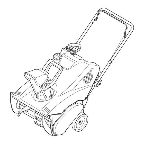
Controls and Features Recoil Starter Handle Ignition Key Auger Control Primer Gas Cap Control Handle Chute Assembly Spark Plug/ Spark Plug Boot Exhaust Choke Lever Shave Plate Auger Recoil Oil Fill Cap Starter w/ Dipstick Handle Oil Drain Figure 4-1 Recoil Starter Choke Lever The starter handle is used to manually start the engine. -
Page 11: Chute Assembly
Chute Assembly Rotate the discharge chute to the left or right using the chute handle. The pitch of the discharge chute controls the angle at which the snow is thrown. Loosen the wing knob on the side of the discharge chute before pivoting the discharge chute upward or downward. -
Page 12: Operation
Operation Before Starting As the engine warms up and begins to operate evenly, slide the choke lever slowly to the 1⁄2 choke position. When the engine begins to run smoothly, move the choke to the OFF WARNING! Read, understand and follow all the position. - Page 13 Notes 5 — O ectiOn peratiOn...
-
Page 14: Maintenance & Adjustment
Maintenance & Adjustments Adjustments Control Cable As a result of both the control cable and the auger drive belt WARNING! Before Servicing, repairing or stretching due to wear, periodic adjustments may be necessary. If inspecting the snow thrower, disengage the auger the auger seems to hesitate when rotating, proceed as follows: control. -
Page 15: Engine Maintenance
Engine Maintenance WARNING! Periodic inspection and adjustment of the engine is essential if To prevent accidental start-up, shut off high level performance is to be maintained. Regular maintenance the engine and remove the ignition key before will also ensure a long service life. The required service intervals performing any type of engine maintenance. -
Page 16: Spark Plug
Spark Plug Oil Recommendations When adding oil to the engine, refer to the viscosity chart WARNING! DO NOT check for a spark with the below (Fig. 7-2). Engine oil capacity is 600 ml (approx. 20 spark plug removed. DO NOT crank the engine with oz.). - Page 17 Off-Season Storage Measure the plug gap with a feeler gauge. Correct as necessary by bending the side electrode, Fig. 7-4. The gap Engines stored over 30 days need to be drained of fuel to should be set to .02-.03 inches (0.60-0.80 mm). prevent deterioration and gum from forming in the fuel system or on essential carburetor parts.
-
Page 18: Service
Service Replacing Belt To replace the belt follow these instructions and refer to Fig. 7-2: Remove the belt cover by removing the five hex screws that secure it to the frame. See Fig. 7-1. Auger Pulley Idler Pulley Engine Pulley Belt Keeper Hex Screws Figure 7-2... - Page 19 Replacing Auger Paddles The snow thrower auger’s rubber paddles are subject to wear and should be replaced if any signs of excessive wear are present. CAUTON: Do NOT allow the auger’s rubber paddles to wear to the point where portions of the metal auger itself can come in contact with the pavement.
-
Page 20: Troubleshooting
Troubleshooting Problem Cause Remedy Engine Fails to start Fuel tank empty, or stale fuel. Fill tank with clean fresh gasoline. Blocked fuel line. Clean fuel line. Key not inserted all the way. Insert key all the way. Spark plug wire disconnected. Connect wire to spark plug. -
Page 21: Replacement Parts
Replacement Parts Component Part Number and Description 731-1033 Shave Plate 754-0101A Belt V-Type 735-04032 Spiral Crescent 735-04033 Rubber Paddle 753-04472 Replacement Kit (includes 4 crescents, 2 paddles and hardware) 731-05632 746-04237 Clutch Cable 951-10292 Spark Plug Phone (800) 800-7310 to order replacement parts or a complete Parts Manual (have your full model number and serial number ready). Parts Manual downloads are also available free of charge at www.mtdproducts.com. - Page 22 Elsewhere in the United States, new non-road, spark-ignition engines certified for model 2005 and later, must meet similar standards set forth by the U. S. EPA. MTD must warranty the emission control system on your engine for the period of time listed below, provided there has been no abuse, neglect or improper maintenance of your small off-road engine.
- Page 23 (c) MTD will include a copy of the following emission warranty parts list with each new engine, using those portions of the list applicable to the engine.
- Page 24 MANUFACTURER’S LIMITED WARRANTY FOR The limited warranty set forth below is given by MTD LLC with c. Service completed by someone other than an authorized service respect to new merchandise purchased and used in the United States dealer. and/or its territories and possessions, and by MTD Products Limited d.
- Page 25 Medidas importantes de seguridad • Configuración • Funcionamiento • Mantenimiento • Servicio • Solución de problemas • Garantía anual del peradOr Máquina quitanieve de etapa única — Modelo 2M1 ADVERTENCIA LEA Y RESPETE TODAS LAS NORMAS DE SEGURIDAD E INSTRUCCIONES INCLUIDAS EN ESTE MANUAL ANTES DE PONER EN FUNCIONAMIENTO ESTA MÁQUINA.
- Page 26 Elija entre las opciones que se presentan a continuación: ◊ Visite nuestro sitio web en www.mtdproducts.com ◊ Llame a un representante de Asistencia al Cliente al (800) 800-7310 or (330) 220-4683 ◊ Escríbanos a MTD LLC • P.O. Box 361131 • Cleveland, OH • 44136-0019...
-
Page 27: Medidas Importantes De Seguridad
Medidas importantes de seguridad ADVERTENCIA! ¡ La presencia de este símbolo indica que se trata de instrucciones importantes de seguridad que se deben respetar para evitar poner en peligro su seguridad personal y/o material y la de otras personas. Lea y siga todas las instrucciones de este manual antes de poner en funcionamiento esta máquina. - Page 28 Manejo seguro de la gasolina Nunca opere la máquina si falta un montaje del canal o si el mismo está dañado. Mantenga todos los dispositivos de Para evitar lesiones personales o daños materiales tenga mucho seguridad en su lugar y en funcionamiento. cuidado cuando trabaje con gasolina.
- Page 29 Mantenimiento y Almacenamiento No modifique el motor Nunca altere los dispositivos de seguridad. Controle Para evitar lesiones graves o la muerte, no modifique el motor periódicamente que funcionen correctamente. Remítase a bajo ninguna circunstancia. Si cambia la configuración del las secciones de mantenimiento y ajuste de este manual. regulador el motor puede descontrolarse y operar a velocidades inseguras.
- Page 30 Símbolos de Seguridad Esta página describe los símbolos y figuras de seguridad internacionales que pueden aparecer en este producto. Lea el manual del operador para obtener la información terminada sobre seguridad, reunirse, operación y mantenimiento y reparación. Símbolo Descripción LEA EL MANUAL DEL OPERADOR (S) Lea, entienda, y siga todas las instrucciones en el manual (es) antes de intentar reunirse y funcionar.
-
Page 31: Montaje Y Configuración
Montaje y Configuración Contenido de la caja • Dos llaves de encendido • Una botella de 20 oz. de aceite • Un Manual del Operador de la 5W-30 Máquina Quitanieve NOTA: Ajuste las perillas de aletas para sujetar la manija en su Todas las referencias a los lados derecho o izquierdo de lugar. - Page 32 Carga de combustible Agregue aceite lentamente hasta que el registro marque entre nivel alto (H) y bajo (L), Figura 3-4. Consulte la ¡ADVERTENCIA! Tenga mucho cuidado al trabajar sección Mantenimiento del motor para ver la viscosidad y con gasolina. La gasolina es sumamente inflamable capacidad de aceite del motor correctas.
- Page 33 Ajustes Montaje del canal La inclinación del montaje del canal controla el ángulo con el que se arroja la nieve. Afloje la perilla de paletas que se encuentra del lado izquierdo del montaje del canal y gire el canal superior hacia arriba o hacia abajo hasta alcanzar la inclinación deseada.
-
Page 34: Controles Y Características
Controles y Características Manija del arrancador de retroceso Llave de encendido Control de la barrena Cebador Tapa de combustible Manija de control Montaje del canal Bujía / Funda de la bujía Escape Palanca del Placa de cebador raspado Tapón de Barrena llenado de aceite c/ varilla... - Page 35 Montaje del canal Haga rotar el canal de descarga hacia la izquierda o derecha usando la manija del canal. La inclinación del canal de descarga controla el ángulo con el que se arroja la nieve. Afloje la perilla de aletas del costado del canal de descarga antes de girar el canal de descarga hacia arriba o hacia abajo.
-
Page 36: Funcionamiento
Funcionamiento Antes de encender la máquina Tire de la manija del arrancador rápidamente. No permita que la manija retroceda a su posición original. Permita que ¡ADVERTENCIA! Lea, comprenda y siga todas se enrolle lentamente mientras sujeta firmemente la manija las instrucciones y advertencias que aparecen en la del arrancador. - Page 37 Notas 5— f ección unciOnaMientO...
-
Page 38: Mantenimiento Y Ajustes
Mantenimiento y Ajustes Ajustes Cable de control Es posible que necesite realizar ajustes periódicos debido al ¡ADVERTENCIA! Antes de realizar tareas de estiramiento del cable de control y de la correa de transmisión mantenimiento, reparación o inspección en la ocasionado por el desgaste. Si la barrena parece titubear máquina quitanieve, desengrane el control de la mientras gira, haga lo siguiente: barrena. -
Page 39: Mantenimiento Del Motor
Mantenimiento del motor ¡ADVERTENCIA! La inspección y los ajustes periódicos del motor son esenciales Para evitar el arranque accidental, apague el si se desea mantener un alto nivel de desempeño. El motor y retire la llave de encendido antes de realizar cualquier mantenimiento regular también garantizará... - Page 40 Bujía de encendido Recomendaciones sobre el aceite Cuando le agregue aceite al motor, consulte la siguiente tabla ¡ADVERTENCIA! NO pruebe la chispa si no está la de viscosidad (Fig. 7-2). La capacidad de aceite del motor es 600 bujía de encendido. NO dé arranque al motor si no ml (aprox.
- Page 41 Almacenamiento fuera de temporada Mida la separación de bujía con un calibrador. Realice los ajustes necesarios torciendo el electrodo lateral, Fig. 7-4. La Los motores que se almacenan durante más de 30 días deben separación de ajustarse en 0,02-0,03 pulgadas (0,60-0,80 ser drenados de combustible para evitar que se deterioren y mm).
-
Page 42: Servicio
Servicio Reemplazo de las correas Para volver a colocar la correa siga estas instrucciones y consulte la Fig. 7-2: Para sacar la cubierta de la correa saque los cinco tornillos hexagonales y las arandelas que la sujetan al bastidor. Vea la Fig. - Page 43 Reemplazo de las paletas de la barrena Las paletas de caucho de la barrena de la máquina quitanieve se desgastan y se las debe cambiar si se presentan signos de desgaste excesivo. PRECAUCIóN: NO permita que las paletas de caucho de la barrena se desgasten hasta el punto en que partes de la barrena metálica misma toquen el pavimento.
-
Page 44: Solución De Problemas
Solución de Problemas Problema Causa Solución El motor no arranca El depósito de combustible está vacío o el Llene el depósito con gasolina limpia y combustible se ha echado a perder. nueva. La línea del combustible está bloqueada. Limpie la línea del combustible. No se introdujo completamente la llave. - Page 45 Notas...
- Page 46 California y en otra parte en la Cobertura de Garantía de Defectos de Control de Emisión de los Estados Unidos El Bordo de Recursos de Aire de California (CARB), la U. S. EPA y MTD se complacen en explicar la garantía del sistema de control de emisiones de su motor para equipo todo terreno, modelo, año 2005 y versiones posteriores.
- Page 47 (c) MTD incluirá una copia de la siguiente lista de piezas bajo garantía contra emisiones con cada nuevo motor, utilizando las partes de la lista aplicables al motor.
-
Page 48: Piezas De Reemplazo
MTD para su uso con el (los) producto(s) incluido(s) en este manual con su identificación. Ninguna otra garantía expresa, oral o anulará...
Need help?
Do you have a question about the 2M1 and is the answer not in the manual?
Questions and answers