Table of Contents
Advertisement
Advertisement
Table of Contents

Related Manuals for Spectra Precision Focus 10


Summary of Contents for Spectra Precision Focus 10
- Page 3 Spectra Precision ® FOCUS ® User Guide Version 02.00 Part Number 571 257 201 August 2007...
- Page 4 Spectra Precision, registered in the Europe United States Patent and Trademark Office and other This product has been countries. Spectra Precision logo is a Trademark of tested and found to Spectra Precision. comply with the All other trademarks are the property of their requirements for a Class B device pursuant to respective owners.
- Page 5 accordance with the instructions, may cause harmful interference to radio communication. However, there is no guarantee that interference will not occur in a particular installation. If this equipment does cause harmful interference to radio or television reception, which can be determined by turning the equipment off and on, the user is encouraged to try to correct the interference by one or more of the following...
-
Page 7: Important Information
Important Information ® ® Before using the Spectra Precision FOCUS 10, make sure that you understand this User Guide, as well as all equipment and jobsite safety requirements. Laser Safety This equipment has been tested and found to comply with IEC 60825-1 January 2001, 21 CFR 1040.10 and 1040.11 except for... - Page 8 USA) Fax +1-937-233-9661 Spectra Precision FOCUS 10 The FOCUS 10 contains one light source: A laser diode for the distance measuring function operating at 850 nm (infrared, non-visible light), with a beam divergence of 0.4 x 0.8 mrad and an output power of < 0.48 mW, laser CLASS 1.
- Page 9 As Spectra Precision makes additional recycling facilities available for your use, we will post their locations and contact information to our Recycling Instructions web page.
-
Page 10: Declaration Of Conformity
Declaration of Conformity EC-Declaration of Conformity to the Essential Requirements of the applicable Directives, 89/336/EC and 73/23/EEC including amendments by the CE marking Directive, 93/68/EEC Product: Instrument – Spectra Precision Focus 10 Types/Models Part Numbers Notes Focus 10 X 571257003, 572257003... -
Page 11: Table Of Contents
Table of Contents Welcome Welcome to Spectra Precision FOCUS 10 ....1-2 Glossary of terms used with the System (Only with FOCUS 10 CU) ..............1-2 Introduction Unpacking & Inspection ..........2-3 Inspection..............2-3 Controls ................. 2-4 Pre-Measurement ............2-6 Connecting the external battery to the instrument .. - Page 12 Table of Contents Dual Axis Compensator..........4-3 Correction for Collimation Errors......... 4-4 Correction for Trunnion Axis Tilt......... 4-4 Single-Face Angle Measurement........4-5 Two-Face Angle Measurement........4-5 Distance Measurement System Overview................ 5-3 Distance Measurement..........5-3 Automatic control of signal level........5-4 Measurement range and accuracy .........
- Page 13 Table of Contents Power Supply Batteries............... 10-2 Internal Battery unit (Central unit) ......10-2 External Battery/Radio Battery........10-2 Single Adapter ............10-3 Multi Adapter.............. 10-4 Battery Cables............. 10-5 Battery Charging............10-6 Single Charger (572 906 330)........10-6 Super Charger (572 906 145) (Optional) ....10-7 Power Unit (572 906 146)...........
- Page 14 Table of Contents...
-
Page 15: Welcome
C H A P T E R Welcome Welcome to Spectra Precision FOCUS 10......1-2 Glossary of terms used with the System (Only with FOCUS 10 CU)..................1-2... -
Page 16: Glossary Of Terms Used With The System (Only With Focus 10 Cu)
Wellcome to the Spectra Precision FOCUS 10 User Guide. This manual describes the different functions of the FOCUS 10 total station and how to best use it in order to get most out of your equipment. Even if you have used other surveying equipment before, it is reccomended that spend some time reading this guide to learn about the special features of this product. - Page 17 Glossary of terms used with the System (Only with FOCUS 10 CU) FSTD: Fast Standard measurement, with A/M. Instrument height over the point. Job File: A file in a the memory device that holds data collected in the field. This file can consist of any data.
- Page 18 1 Welcome collected, its order of collection and how it is displayed on the screen.vm dELE Point to set out 1-4 Spectra Precision FOCUS 10 User Guide...
-
Page 19: Introduction
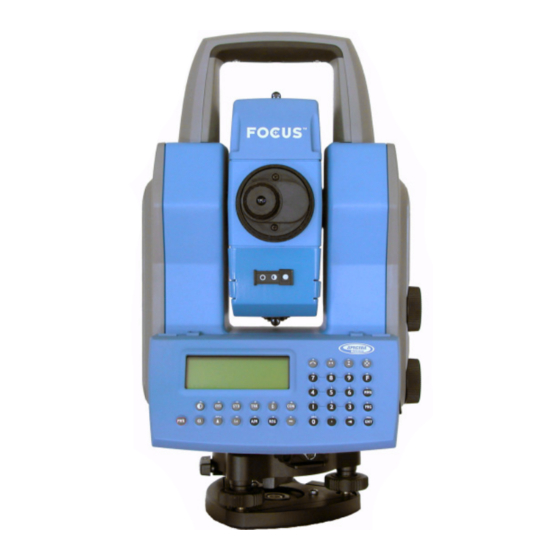
Unpacking & Inspection ............2-3 Inspection................ 2-3 Controls................2-4 Pre-Measurement ..............2-6 Connecting the external battery to the instrument ..2-6 The Side Cover ..............2-7 The Central Unit ..............2-8 Laser and LED Information ..........2-9 Spectra Precision FOCUS 10 ......... 2-9... - Page 20 2 Introduction Figure 2.1 FOCUS 10 Series 2-2 Spectra Precision FOCUS 10 User Guide...
-
Page 21: Unpacking & Inspection
Unpacking & Inspection Unpacking & Inspection Before we begin to describe the operating procedure of your Spectra Precision FOCUS 10, it is first necessary to acquaint yourself with the equipment received: • Instrument Unit • Transport case • Tribrach • Rain cover •... -
Page 22: Controls
Coarse sight Central unit - Internal battery or Tracklight and/or Tracker Vertical motion servo control Horizontal motion servo control Figure 2.2 FOCUS 10 instrument shown from the operator side (back). 2-4 Spectra Precision FOCUS 10 User Guide... - Page 23 Controls Prism symbol (which marks the instrument height (IH), also on the opposite side cover) Figure 2.3 FOCUS 10 instrument seen from the side. Spectra Precision FOCUS 10 User Guide 2-5...
-
Page 24: Pre-Measurement
The cable is to be connected to the connector on the instrument resp. battery as shown in the picture below. Figure 2.4 Connecting the external battery to the instrument. 2-6 Spectra Precision FOCUS 10 User Guide... -
Page 25: The Side Cover
Spectra Precision authorized service center. Plain Cover Radio Unit Cover The radio unit cover is needed when you wish to use the instrument for remote surveying or robotic surveying (one-person total station), Equipment Spectra Precision FOCUS 10 User Guide 2-7... -
Page 26: The Central Unit
® the Tracklight or the tracker unit. You can change between battery unit and Tracklight by yourself, but the tracker unit must be installed at a Spectra Precision authorized service center. Internal battery The internal battery gives you 2 hours of continuous use. -
Page 27: Laser And Led Information
Laser and LED Information Laser and LED Information Spectra Precision FOCUS 10 The FOCUS 10 has been tested and complies with the regulations for a Class 1 Laser product. See laser safety information on the first pages of this manual. - Page 28 2 Introduction 2-10 Spectra Precision FOCUS 10 User Guide...
-
Page 29: Surveying Methods
C H A P T E R Surveying methods Overview ................3-2 Conventional surveying with servo........3-2 Conventional surveying with Autolock........3-3 Aiming ................3-3 How to Check Aiming............3-4 Robotic Surveying ..............3-5 Equipment............... 3-5... -
Page 30: Overview
Overview This chapter will describe the different ways of working with the FOCUS 10. Since the instrument is equipped with servo drive, you’ll find that the system is very easy to handle, when setting out you can with a touch of a single key aim the instrument towards the set out point. -
Page 31: Conventional Surveying With Autolock
Autolock, figure 3.1. This is not a problem since the two axis have their own separate collimation data. It is however important to make collimation test for both axes. Spectra Precision FOCUS 10 User Guide 3-3... -
Page 32: How To Check Aiming
3. Compare the angles between manual and Autolock aiming. If the difference between the read out angles is significant, you should carry out both a horizontal and vertical angle 3-4 Spectra Precision FOCUS 10 User Guide... -
Page 33: Robotic Surveying
RMT (Remote Target) and an external radio connected to the collector. The data collector, external radio and RMT will hereafter be called, Robotic rod. Spectra Precision FOCUS 10 User Guide 3-5... - Page 34 3 Surveying methods 3-6 Spectra Precision FOCUS 10 User Guide...
-
Page 35: Angle Measurement System
C H A P T E R Angle Measurement System Overview ................4-3 The Angle Measuring Technique.......... 4-3 Dual Axis Compensator ..........4-3 Correction for Collimation Errors........4-4 Correction for Trunnion Axis Tilt........4-4 Single-Face Angle Measurement........4-5 Single-Face Angle Measurement......... 4-5 Two-Face Angle Measurement .......... -
Page 36: Correction For Trunnion Axis Tilt
4 Angle Measurement System Automatic correction for deviation in relation to the plumb axis Automatic correction for collimation error Automatic correction for trunnion axis tilt Figure 4.1 The Angle Measurement System 4-2 Spectra Precision FOCUS 10 User Guide... -
Page 37: Overview
• Arithmetic averaging for elimination of pointing errors. The Angle Measuring Technique One of the strong features of the design of the FOCUS 10 is its electronic angle measurement system, which eliminates the angle errors that normally occur in conventional theodolites. -
Page 38: Correction For Collimation Errors
2. When the temperature differs by > 10 ºC from the previous application. 3. Immediately prior to high precision angle measurement. How are these tests carried out? See “Test Measurements”, chapter 4 in FOCUS 10 CU User Guide General Part 1. 4-4 Spectra Precision FOCUS 10 User Guide... -
Page 39: Single-Face Angle Measurement
When measuring in STD-mode you measure and store each angle value of the two faces and get a display value of the total collimation and sighting error. Spectra Precision FOCUS 10 User Guide 4-5... - Page 40 The number of repeated sightings can be chosen depending on the current measuring conditions. The final mean value calculated angles are displayed and stored in this mode. Angle values for each face are also available. 4-6 Spectra Precision FOCUS 10 User Guide...
-
Page 41: Distance Measurement System
C H A P T E R Distance Measurement System Overview ................5-3 Distance Measurement ............5-3 Automatic control of signal level ........5-4 Measurement range and accuracy ......... 5-4... - Page 42 5 Distance Measurement System 5-2 Spectra Precision FOCUS 10 User Guide...
-
Page 43: Distance Measurement
Overview Overview The distance module of FOCUS 10 operates within the infrared area of the electromagnetic spectrum. It transmits an infrared light beam. The reflected light beam is received by the instrument and, with the help of a comparator, the phase delay between transmitted an received signal is measured. -
Page 44: Automatic Control Of Signal Level
Automatic control of signal level The FOCUS 10 total station has an automatic signal control which adjusts the measurement signal level to an optimal value of each distance measured. -
Page 45: Servo
C H A P T E R Servo Overview ................6-2 Servo controls ..............6-2 Motion knobs..............6-2... -
Page 46: Overview
6 Servo Overview The FOCUS 10 is equipped with servo controlled motors for positioning of the unit. The servo is in use when performing a number of different operations; when turning the motion knobs, when positioning with the servo control keys, for automatic test and calibration or when using the tracker for robotic surveying.. -
Page 47: Tracklight
C H A P T E R Tracklight Overview ................7-3... - Page 48 7 Tracklight Tracklight ® emits a red, white and green sector of Figure 7.1 flashing light where the white light coincides with the measuring beam. 7-2 Spectra Precision FOCUS 10 User Guide...
-
Page 49: Overview
The Tracklight unit slides onto the underside of the measuring unit or if the instrument is equipped with a tracker the Tracklight is a part of the tracker unit. The Tracklight is activated from the data collector. Spectra Precision FOCUS 10 User Guide 7-3... - Page 50 7 Tracklight 7-4 Spectra Precision FOCUS 10 User Guide...
-
Page 51: Tracker
C H A P T E R Tracker Overview ................8-2... -
Page 52: Overview
8 Tracker Overview FOCUS 10 can be equipped with a Tracker unit which is needed when using the system for robotic surveying or when performing conventional surveying with Autolock. The tracker has control over the instrument’s servos and aims the instrument correctly towards the target, which in these cases must be an RMT (Remote Target). -
Page 53: Radio
C H A P T E R Radio Overview ................9-2 Radio controls ..............9-2 Select radio channel ............9-2 Station address ............... 9-2 Radio license ..............9-3 Range ................9-3... -
Page 54: Overview
The range of different channels makes it possible to work with more then one FOCUS 10 at a working site. It is though important that each system has its own radio channel so that not any disturbances will occur. -
Page 55: Radio License
The actual range in which the radio can work is depending on the conditions. Range can be decreased if other radios are in operation in your area or when you are working in an area with many reflecting objects. Spectra Precision FOCUS 10 User Guide 9-3... - Page 56 9 Radio 9-4 Spectra Precision FOCUS 10 User Guide...
-
Page 57: Power Supply
C H A P T E R Power Supply Batteries ................10-2 Internal Battery unit (Central unit) ......... 10-2 External Battery/Radio Battery........10-2 Single Adapter .............. 10-3 Multi Adapter..............10-4 Battery Cables .............. 10-5 Battery Charging ..............10-6 Power Unit (572 906 146) ..........10-8 About charging NiMH (and NiCd) batteries.... -
Page 58: Batteries
External Battery/Radio Battery The external NiMH 12V, 3.5 Ah battery (Part No. 572 204 270), which is also common to other Spectra Precision products, is connected to the instrument via the Single Adapter (Part No. 572 204 256) or Multi Adapter (Part No. -
Page 59: Single Adapter
The Single Adapter (Part No. 572 204 256) is used when you want to connect the External NiMH Battery (Part No. 572 204 270) to a FOCUS 10 via a standard Hirose cable. The adapter slides onto the upper side of the External Battery. -
Page 60: Multi Adapter
The Multi Adapter (Part No. 572 204 273) is used to connect up to three External NiMH Battery units (Part No. 572 204 270) to a FOCUS 10 via a standard Hirose cable. The adapter slides onto the upper sides of the External Batteries. -
Page 61: Battery Cables
The different types of cables are listed below: Multi functional Cable 1m, 572 202 188, for connecting the FOCUS 10 or control unit to an external battery via the Single or Multi Adapter or to another control unit or instrument. Length: 1.0m. -
Page 62: Battery Charging
10 Power Supply Battery Charging When charging the batteries to a FOCUS 10, it is important to use a charger dedicated to charging NiMh and NiCd batteries. The different types of chargers available are described in the following. Single Charger (572 906 330) A 230 or 115 VAC single battery charger. -
Page 63: Super Charger (572 906 145) (Optional)
Super Charger (572 906 145) (Optional) A microprocessor controlled charger for sequential charging of up to four Spectra Precision NiMH or NiCd batteries. It is run with 10-30 VDC and is fitted with a connector to suit both 19mm and 12mm cigarette lighter sockets. -
Page 64: Power Unit (572 906 146)
Super Charger (572 906 145). The Power Unit is equipped with a cigarette lighter socket and two Hirose connectors for FOCUS 10 system cabling. Use together with Power Cable 571 905 924 (230V), 571 905 925 (100-115V) or 571 908 040 (230V, UK plug). -
Page 65: Bat Low
Note – This safety backup of the instrument’s parameters and functions will work only when “Bat Low” appears on the display: It will not function if the battery is removed during operation. Spectra Precision FOCUS 10 User Guide 10-9... - Page 66 10 Power Supply 10-10 Spectra Precision FOCUS 10 User Guide...
-
Page 67: Rmt Remote Targets
C H A P T E R RMT Remote Targets Overview ............... 11-2 RMT 602 ............... 11-3 RMT 606 ............... 11-4... -
Page 68: Overview
11 RMT Remote Targets Overview FOCUS 10 instruments equipped with an optional Tracker unit can perform surveying tasks using the Autolock function. If the instrument is upgraded with a radio, you will also be able to perform Robotic surveying, i.e one- person surveying. -
Page 69: Rmt 602
RMT 602 RMT602 (Part No. 572 202 220) is the standard remote target for FOCUS 10. It can be used for distances up to 350 m and consists of a tracker diode unit with a miniature prism (Part No. 571 126 060) mounted in front (not included). -
Page 70: Rmt 606
RMT 606 RMT606 (Part No. 572 204 610) is an optional 360° remote target for FOCUS 10. It can be used for distances up to 350 m. The RMT consists of a tracker diode unit with a set of active diodes forming a full 360 degree circle and a 360°... -
Page 71: Care & Maintenance
C H A P T E R Care & Maintenance Overview ................12-2 Cleaning ................12-3 Condensation ..............12-3 Packing for Transport............12-3 Service ................12-3... -
Page 72: Overview
Great variations of instrument temperature could affect the precision. Warning – The FOCUS 10 is designed to withstand normal electromagnetic disturbance from the environment. However, the instrument contains circuits sensitive to static electricity and the instrument cover must not be removed by unauthorized personnel. -
Page 73: Cleaning
We recommend that you, once a year, leave the instrument to an authorized service workshop for service. This is to guarantee that the specified accuracies are maintained. Note that there are no user servicable parts inside the instrument. Spectra Precision FOCUS 10 User Guide 12-3... - Page 74 12 Care & Maintenance 12-4 Spectra Precision FOCUS 10 User Guide...
- Page 76 Spectra Precision 7401 Church Ranch Blvd Westminster, CO 80021 +1-303-323-4100 Phone 888-477-7516 (Toll Free in USA) www.spectraprecision.com...
Need help?
Do you have a question about the Focus 10 and is the answer not in the manual?
Questions and answers